EP1237444B1 - Support arm for visual display unit - Google Patents
Support arm for visual display unit Download PDFInfo
- Publication number
- EP1237444B1 EP1237444B1 EP00974177A EP00974177A EP1237444B1 EP 1237444 B1 EP1237444 B1 EP 1237444B1 EP 00974177 A EP00974177 A EP 00974177A EP 00974177 A EP00974177 A EP 00974177A EP 1237444 B1 EP1237444 B1 EP 1237444B1
- Authority
- EP
- European Patent Office
- Prior art keywords
- arm
- visual display
- display unit
- pivot
- supporting
- Prior art date
- Legal status (The legal status is an assumption and is not a legal conclusion. Google has not performed a legal analysis and makes no representation as to the accuracy of the status listed.)
- Expired - Lifetime
Links
Images


Classifications
-
- F—MECHANICAL ENGINEERING; LIGHTING; HEATING; WEAPONS; BLASTING
- F16—ENGINEERING ELEMENTS AND UNITS; GENERAL MEASURES FOR PRODUCING AND MAINTAINING EFFECTIVE FUNCTIONING OF MACHINES OR INSTALLATIONS; THERMAL INSULATION IN GENERAL
- F16M—FRAMES, CASINGS OR BEDS OF ENGINES, MACHINES OR APPARATUS, NOT SPECIFIC TO ENGINES, MACHINES OR APPARATUS PROVIDED FOR ELSEWHERE; STANDS; SUPPORTS
- F16M11/00—Stands or trestles as supports for apparatus or articles placed thereon ; Stands for scientific apparatus such as gravitational force meters
- F16M11/20—Undercarriages with or without wheels
- F16M11/24—Undercarriages with or without wheels changeable in height or length of legs, also for transport only, e.g. by means of tubes screwed into each other
-
- A—HUMAN NECESSITIES
- A47—FURNITURE; DOMESTIC ARTICLES OR APPLIANCES; COFFEE MILLS; SPICE MILLS; SUCTION CLEANERS IN GENERAL
- A47B—TABLES; DESKS; OFFICE FURNITURE; CABINETS; DRAWERS; GENERAL DETAILS OF FURNITURE
- A47B81/00—Cabinets or racks specially adapted for other particular purposes, e.g. for storing guns or skis
- A47B81/06—Furniture aspects of radio, television, gramophone, or record cabinets
- A47B81/061—Furniture aspects of radio, television, gramophone, or record cabinets the device supports being adjustable
-
- F—MECHANICAL ENGINEERING; LIGHTING; HEATING; WEAPONS; BLASTING
- F16—ENGINEERING ELEMENTS AND UNITS; GENERAL MEASURES FOR PRODUCING AND MAINTAINING EFFECTIVE FUNCTIONING OF MACHINES OR INSTALLATIONS; THERMAL INSULATION IN GENERAL
- F16M—FRAMES, CASINGS OR BEDS OF ENGINES, MACHINES OR APPARATUS, NOT SPECIFIC TO ENGINES, MACHINES OR APPARATUS PROVIDED FOR ELSEWHERE; STANDS; SUPPORTS
- F16M11/00—Stands or trestles as supports for apparatus or articles placed thereon ; Stands for scientific apparatus such as gravitational force meters
- F16M11/02—Heads
- F16M11/04—Means for attachment of apparatus; Means allowing adjustment of the apparatus relatively to the stand
- F16M11/041—Allowing quick release of the apparatus
-
- F—MECHANICAL ENGINEERING; LIGHTING; HEATING; WEAPONS; BLASTING
- F16—ENGINEERING ELEMENTS AND UNITS; GENERAL MEASURES FOR PRODUCING AND MAINTAINING EFFECTIVE FUNCTIONING OF MACHINES OR INSTALLATIONS; THERMAL INSULATION IN GENERAL
- F16M—FRAMES, CASINGS OR BEDS OF ENGINES, MACHINES OR APPARATUS, NOT SPECIFIC TO ENGINES, MACHINES OR APPARATUS PROVIDED FOR ELSEWHERE; STANDS; SUPPORTS
- F16M11/00—Stands or trestles as supports for apparatus or articles placed thereon ; Stands for scientific apparatus such as gravitational force meters
- F16M11/02—Heads
- F16M11/04—Means for attachment of apparatus; Means allowing adjustment of the apparatus relatively to the stand
- F16M11/06—Means for attachment of apparatus; Means allowing adjustment of the apparatus relatively to the stand allowing pivoting
- F16M11/12—Means for attachment of apparatus; Means allowing adjustment of the apparatus relatively to the stand allowing pivoting in more than one direction
- F16M11/14—Means for attachment of apparatus; Means allowing adjustment of the apparatus relatively to the stand allowing pivoting in more than one direction with ball-joint
-
- F—MECHANICAL ENGINEERING; LIGHTING; HEATING; WEAPONS; BLASTING
- F16—ENGINEERING ELEMENTS AND UNITS; GENERAL MEASURES FOR PRODUCING AND MAINTAINING EFFECTIVE FUNCTIONING OF MACHINES OR INSTALLATIONS; THERMAL INSULATION IN GENERAL
- F16M—FRAMES, CASINGS OR BEDS OF ENGINES, MACHINES OR APPARATUS, NOT SPECIFIC TO ENGINES, MACHINES OR APPARATUS PROVIDED FOR ELSEWHERE; STANDS; SUPPORTS
- F16M11/00—Stands or trestles as supports for apparatus or articles placed thereon ; Stands for scientific apparatus such as gravitational force meters
- F16M11/20—Undercarriages with or without wheels
- F16M11/2007—Undercarriages with or without wheels comprising means allowing pivoting adjustment
- F16M11/2035—Undercarriages with or without wheels comprising means allowing pivoting adjustment in more than one direction
- F16M11/2064—Undercarriages with or without wheels comprising means allowing pivoting adjustment in more than one direction for tilting and panning
-
- G—PHYSICS
- G06—COMPUTING OR CALCULATING; COUNTING
- G06F—ELECTRIC DIGITAL DATA PROCESSING
- G06F1/00—Details not covered by groups G06F3/00 - G06F13/00 and G06F21/00
- G06F1/16—Constructional details or arrangements
- G06F1/1601—Constructional details related to the housing of computer displays, e.g. of CRT monitors, of flat displays
-
- F—MECHANICAL ENGINEERING; LIGHTING; HEATING; WEAPONS; BLASTING
- F16—ENGINEERING ELEMENTS AND UNITS; GENERAL MEASURES FOR PRODUCING AND MAINTAINING EFFECTIVE FUNCTIONING OF MACHINES OR INSTALLATIONS; THERMAL INSULATION IN GENERAL
- F16M—FRAMES, CASINGS OR BEDS OF ENGINES, MACHINES OR APPARATUS, NOT SPECIFIC TO ENGINES, MACHINES OR APPARATUS PROVIDED FOR ELSEWHERE; STANDS; SUPPORTS
- F16M2200/00—Details of stands or supports
- F16M2200/02—Locking means
- F16M2200/025—Locking means for translational movement
- F16M2200/028—Locking means for translational movement by positive interaction, e.g. male-female connections
-
- F—MECHANICAL ENGINEERING; LIGHTING; HEATING; WEAPONS; BLASTING
- F16—ENGINEERING ELEMENTS AND UNITS; GENERAL MEASURES FOR PRODUCING AND MAINTAINING EFFECTIVE FUNCTIONING OF MACHINES OR INSTALLATIONS; THERMAL INSULATION IN GENERAL
- F16M—FRAMES, CASINGS OR BEDS OF ENGINES, MACHINES OR APPARATUS, NOT SPECIFIC TO ENGINES, MACHINES OR APPARATUS PROVIDED FOR ELSEWHERE; STANDS; SUPPORTS
- F16M2200/00—Details of stands or supports
- F16M2200/04—Balancing means
- F16M2200/044—Balancing means for balancing rotational movement of the undercarriage
-
- G—PHYSICS
- G06—COMPUTING OR CALCULATING; COUNTING
- G06F—ELECTRIC DIGITAL DATA PROCESSING
- G06F2200/00—Indexing scheme relating to G06F1/04 - G06F1/32
- G06F2200/16—Indexing scheme relating to G06F1/16 - G06F1/18
- G06F2200/161—Indexing scheme relating to constructional details of the monitor
- G06F2200/1612—Flat panel monitor
-
- Y—GENERAL TAGGING OF NEW TECHNOLOGICAL DEVELOPMENTS; GENERAL TAGGING OF CROSS-SECTIONAL TECHNOLOGIES SPANNING OVER SEVERAL SECTIONS OF THE IPC; TECHNICAL SUBJECTS COVERED BY FORMER USPC CROSS-REFERENCE ART COLLECTIONS [XRACs] AND DIGESTS
- Y10—TECHNICAL SUBJECTS COVERED BY FORMER USPC
- Y10S—TECHNICAL SUBJECTS COVERED BY FORMER USPC CROSS-REFERENCE ART COLLECTIONS [XRACs] AND DIGESTS
- Y10S248/00—Supports
- Y10S248/917—Video display screen support
- Y10S248/919—Adjustably orientable video screen support
- Y10S248/921—Plural angular
Definitions
- the present invention relates to a support arm for a visual display unit and in particular to a support arm for a flat video screen such as a LCD or plasma display screen.
- VDUs visual display units
- liquid crystal display or plasma displays are becoming more prevalent.
- the latter screens are flat and are essentially planar devices compared with a vacuum tube display unit which is both heavy and of considerable depth.
- To mount VDUs on a support column or with a cantilever or articulated arm it is necessary to compensate for the weight of the visual display unit being supported as well as for any couple or moment which is created. As the arm is moved to suit the viewing of the VDU in a working or commercial environment, these parameters change and problems arise in maintaining a stable position for the arm.
- support arms and systems for supporting a VDU primarily a flat panel VDU are disclosed in prior art references WO 97/46824, US 5,751,548, EP 723368, US 5,709,360 and US 5,505,424.
- the support arm comprises means for adjusting the position of a VDU.
- US 4,768,744 corresponding to the preamble of appended claim 1.
- the present invention seeks to overcome problems or disadvantages in the prior art or to ameliorate them or to provide an alternative thereto.
- an apparatus for supporting a visual display unit including a support base, at least one pivot base rotatable with respect to said support base, an arm fixed to and pivotable with respect to said pivot base having means for dampening the motion of said arm and at a free end of said arm a mounting means for mounting a visual display device, said mounting means being pivotable with respect to said arm.
- the pivot base can be rotated through 360° with respect to said support base while said monitor arm can be raised or lowered through 110° in a vertical plane and said mounting means allows the visual display device fixed thereto to be rotated through 180° in the plane of the arm, plus or minus 40° in any other direction, and 360° about the longitudinal axis or roll axis of the arm.
- More than one monitor arm can be attached to the base and the height of the base can be adjusted to suit a given application.
- the monitor can be rotated 360° about the longitudinal axis or roll axis of the arm, for example to change from landscape to portrait position.
- the arm is preferably supported by a gas spring and fixed to the pivot base by a pivot pin e.g. a nut and bolt arrangement. This support and fixing arrangement is damped to allow the arm to be maintained in equilibrium with movement of the arm.
- planar display unit is readily removable from the support arm, including the disconnection of any electrical attachments, by providing ready access thereto.
- the support base may be secured to a support surface for stability.
- the monitor arm support arrangement includes a support base 10, spacer tubes 11 with a pivot base 20 supported thereon, the pivot base 20 being rotatable through 360° with respect to the support base 10 by means of a bearing 12.
- An arm 30 is fixed by a pivot 32 to the post 34 extending from the pivot base 20.
- a mounting plate 40 having open ends 42, 44 and channelled sides 46, 48.
- the open end 44 is wider than the open end 42 creating a divergent channel between the sides 46, 48.
- the support base 10 may include means whereby it can be fixed, for example, removably, to a support surface (not shown) such as a desk, wall, floor, ceiling for stability, the fixing means being within the knowledge of a person skilled in the art.
- the mounting plate 40 is attached to the arm 30 through two pivoting mechanisms, a swivel head 50 and a ball pivot 60.
- the swivel head 50 is fixed to the arm 30 by a pin pivot, for example nut and bolt, 52.
- the swivel head 50 is a flange having a stepped head 54 cut to allow the head 50 to rotate about the stepped end 56 of the arm 30.
- the swivel head 50 can rotate through at least 180° in the plane of the monitor arm 30.
- a ball pivot 60 having a ball part 62 and a socket part 64 of a ball and socket joint.
- the socket 64 on the swivel head 50 mates with the ball 62 at the back 66 of the plate 40.
- the ball pivot 60 allows rotations of the plate 40 through the permitted angle of the ball pivot 60.
- rotation through plus or minus 40° in pitch and/or yaw is provided for the mounting plate 40 with respect to the longitudinal or roll axis of the swivel head 50.
- the arm 30 is supported by a gas spring 70 fixed at one end 72 to the arm 30 and fixed at the other end 74 of the gas spring 70 to the post 34 near the join of the pivot base 20 to the spacer 11.
- the arm 30 is partially hollowed to accommodate the gas spring 70 and to reduce the weight of the arm.
- the other end 74 of the gas spring 70 is supported by a pivoting attachment 76 to accommodate movement of the arm 30 in a vertical plane through the arm 30.
- the pivoting attachment 76 can move vertically to adjust the angle, and hence the weight bearing characteristics, of the gas spring 70.
- the gas spring 70 provides for damped movement of the arm 30.
- the friction provided by the bolt 32 and the bolt 52 provides respectively resistance to the motion of the arm 30 and the swivel head 50. The combination of these two factors allows the position of the plate 40 loaded by a panel display unit attached thereto to remain stationary or stable for any given position to which the arm 30 is moved.
- a bracket 100 is shown allowing quick attaching and detaching of a planar monitor to the arm.
- a back plate 110 attaches the bracket 100 to a monitor 120 (see Fig.4) by fixtures 122 through holes 114.
- the bracket 100 has channels 102, 104 for sliding engagement on sides 46, 48 of mounting plate 40 with the separation of the channels 102, 104 matching the divergence of the sides 46, 48 (see Fig 4).
- the back plate 110 is spaced from the channels 102, 104 by stepped portion 116 to provide clearance for accommodating cabling between the mounting plate 40 and the monitor 120.
- the back plate 110 has cut-out 112 for allowing access to attach or detach the plugs of a monitor 120 once on the bracket 100.
- a lock 130 can be provided in the plate 40 to provide security for the monitor or planar visual display unit 120.
- the lock 130 has a tongue (not shown) which, when rotated to its locking position, engages in the slot 118 holding the mounting plate 40 and bracket 100 together.
- the components of the bracket 100 and the monitor arm such as the support base 10, spacers 11, the pivot base 20, the arm 30, or the plate 40 can be made of any suitable material such as metal or plastics material, within the knowledge of a person skilled in the art.
- the bearing components 12 such as between spacer 11 and the pivot base 20 can be made of nylon and the components of the ball pivot 60 between the swivel head 50 and the plate 40 can be made of materials within the knowledge of a person skilled in the art.
- the ball and socket joint as shown in Figures 2 and 4 is secured to the mounting plate 40 in any manner well known in the art, for example by fixtures 67, to the back 66 of the plate 40.
- An alternative arrangement is shown in Figure 5.
- the back 66 of mounting plate 40 has a truncated conical fixture 150 to which the socket part 64 of the ball and socket joint or ball pivot 60 is attached.
- adjustable fixtures 152 are located about the periphery 154 of socket part 64 and secure the socket part 64 to the fixture 150.
- Springs or similar resilient elements 156 are positioned about each fixture 152 between socket part 64 and conical fixture 150.
- Fixtures 152 may be screws or bolts, for example. Tightening or slackening of fixtures 152 against the restoring force of springs 156 allows adjustment of the pressure applied between the ball and socket components 62, 64 of the ball pivot 60 and thus of its frictional loading.
- Springs 156 also allow the pivot 60 to flex about directions within the plane of the plate 40 or of the planar VDU 120. This arrangement allows dampening of the motion of the pivot 60 and of the VDU held by the plate 40.
- Springs 156 may be coiled springs or may be leaf springs. Other forms of resilient means are contemplated within the knowledge of a person skilled in the art.
- More than one support arm 30 can be supported by the support base 10.
- Figure 6, shows the situation where two support arms 30, 30' are provided, each attached to their respective pivot base 20, 20', including posts 34, 34', and supporting respective VDU 120, 120'.
- Each of the features of the two supporting arrangements 200, 220 is substantially identical to those of the embodiments described above with respect to Figures 1-5.
- Each arm 30, 30' may support a VDU the same as the other or of a different size, weight or construction.
- the VDUs may face the same direction (as shown) or a different direction as required.
- the spacer means 11 may be used to space the pivot bases 20, 20' from the support base 12 or may be used to space the pivot bases 20, 20' apart.
Landscapes
- Engineering & Computer Science (AREA)
- General Engineering & Computer Science (AREA)
- Mechanical Engineering (AREA)
- Theoretical Computer Science (AREA)
- Computer Hardware Design (AREA)
- Human Computer Interaction (AREA)
- Physics & Mathematics (AREA)
- General Physics & Mathematics (AREA)
- Devices For Indicating Variable Information By Combining Individual Elements (AREA)
- Pivots And Pivotal Connections (AREA)
- Fittings On The Vehicle Exterior For Carrying Loads, And Devices For Holding Or Mounting Articles (AREA)
- Spinning Or Twisting Of Yarns (AREA)
Abstract
Description
- The present invention relates to a support arm for a visual display unit and in particular to a support arm for a flat video screen such as a LCD or plasma display screen.
- In the prior art most visual display units (VDUs) are of the vacuum tube type although of recent times liquid crystal display or plasma displays are becoming more prevalent. The latter screens are flat and are essentially planar devices compared with a vacuum tube display unit which is both heavy and of considerable depth. To mount VDUs on a support column or with a cantilever or articulated arm it is necessary to compensate for the weight of the visual display unit being supported as well as for any couple or moment which is created. As the arm is moved to suit the viewing of the VDU in a working or commercial environment, these parameters change and problems arise in maintaining a stable position for the arm.
- Examples of support arms and systems for supporting a VDU, primarily a flat panel VDU are disclosed in prior art references WO 97/46824, US 5,751,548, EP 723368, US 5,709,360 and US 5,505,424. In each of these references the support arm comprises means for adjusting the position of a VDU. A further prior art reference is US 4,768,744 corresponding to the preamble of appended claim 1.
- The present invention seeks to overcome problems or disadvantages in the prior art or to ameliorate them or to provide an alternative thereto.
- According to the invention there is provided an apparatus for supporting a visual display unit including a support base, at least one pivot base rotatable with respect to said support base, an arm fixed to and pivotable with respect to said pivot base having means for dampening the motion of said arm and at a free end of said arm a mounting means for mounting a visual display device, said mounting means being pivotable with respect to said arm.
- Preferably, the pivot base can be rotated through 360° with respect to said support base while said monitor arm can be raised or lowered through 110° in a vertical plane and said mounting means allows the visual display device fixed thereto to be rotated through 180° in the plane of the arm, plus or minus 40° in any other direction, and 360° about the longitudinal axis or roll axis of the arm. More than one monitor arm can be attached to the base and the height of the base can be adjusted to suit a given application. The monitor can be rotated 360° about the longitudinal axis or roll axis of the arm, for example to change from landscape to portrait position.
- The arm is preferably supported by a gas spring and fixed to the pivot base by a pivot pin e.g. a nut and bolt arrangement. This support and fixing arrangement is damped to allow the arm to be maintained in equilibrium with movement of the arm.
- Preferably, the planar display unit is readily removable from the support arm, including the disconnection of any electrical attachments, by providing ready access thereto.
- Preferably, the support base may be secured to a support surface for stability.
- Preferred embodiments of the invention will now be described with respect to the following figures in which:
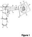
- Figure 1 shows in perspective view a first embodiment of a monitor arm according to the invention;
- Figure 2 shows a rear view of the mounting mechanism of Figure 1;
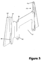
- Figure 3 shows in perspective, a view of a bracket for use with the monitor arm of Figure 1;
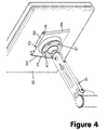
- Figure 4 shows the monitor arm supporting a planar monitor or visual display unit;
- Figure 5 shows an alternative arrangement for fixing the swivel head to the mounting plate for the mounting mechanism according to the invention; and
- Figure 6 shows a further embodiment of the invention illustrating two monitor arms being supported by the support base.
- Referring to Figure 1 the monitor arm support arrangement includes a
support base 10, spacer tubes 11 with apivot base 20 supported thereon, thepivot base 20 being rotatable through 360° with respect to thesupport base 10 by means of abearing 12. Anarm 30 is fixed by apivot 32 to thepost 34 extending from thepivot base 20. At the other end of the arm (see Figure 2) is attached a mountingplate 40 having open ends 42, 44 and channelledsides open end 44 is wider than theopen end 42 creating a divergent channel between thesides support base 10 may include means whereby it can be fixed, for example, removably, to a support surface (not shown) such as a desk, wall, floor, ceiling for stability, the fixing means being within the knowledge of a person skilled in the art. - The mounting
plate 40 is attached to thearm 30 through two pivoting mechanisms, aswivel head 50 and aball pivot 60. Theswivel head 50 is fixed to thearm 30 by a pin pivot, for example nut and bolt, 52. Theswivel head 50 is a flange having a steppedhead 54 cut to allow thehead 50 to rotate about the steppedend 56 of thearm 30. Theswivel head 50 can rotate through at least 180° in the plane of themonitor arm 30. - Attached to the stepped
portion 54 of theswivel head 50 is aball pivot 60 having aball part 62 and asocket part 64 of a ball and socket joint. Thesocket 64 on theswivel head 50 mates with theball 62 at theback 66 of theplate 40. Theball pivot 60 allows rotations of theplate 40 through the permitted angle of theball pivot 60. Preferably, rotation through plus or minus 40° in pitch and/or yaw is provided for the mountingplate 40 with respect to the longitudinal or roll axis of theswivel head 50. - In addition to the
bolt 32, thearm 30 is supported by agas spring 70 fixed at oneend 72 to thearm 30 and fixed at theother end 74 of thegas spring 70 to thepost 34 near the join of thepivot base 20 to the spacer 11. Thearm 30 is partially hollowed to accommodate thegas spring 70 and to reduce the weight of the arm. Theother end 74 of thegas spring 70 is supported by a pivotingattachment 76 to accommodate movement of thearm 30 in a vertical plane through thearm 30. The pivotingattachment 76 can move vertically to adjust the angle, and hence the weight bearing characteristics, of thegas spring 70. - The
gas spring 70 provides for damped movement of thearm 30. In addition, the friction provided by thebolt 32 and thebolt 52 provides respectively resistance to the motion of thearm 30 and theswivel head 50. The combination of these two factors allows the position of theplate 40 loaded by a panel display unit attached thereto to remain stationary or stable for any given position to which thearm 30 is moved. - Referring to Figures 3 and 4, a
bracket 100 is shown allowing quick attaching and detaching of a planar monitor to the arm. Aback plate 110 attaches thebracket 100 to a monitor 120 (see Fig.4) byfixtures 122 throughholes 114. Thebracket 100 haschannels sides plate 40 with the separation of thechannels sides 46, 48 (see Fig 4). - The
back plate 110 is spaced from thechannels portion 116 to provide clearance for accommodating cabling between the mountingplate 40 and themonitor 120. In addition, theback plate 110 has cut-out 112 for allowing access to attach or detach the plugs of amonitor 120 once on thebracket 100. - A
lock 130 can be provided in theplate 40 to provide security for the monitor or planarvisual display unit 120. Thelock 130 has a tongue (not shown) which, when rotated to its locking position, engages in theslot 118 holding the mountingplate 40 andbracket 100 together. - The components of the
bracket 100 and the monitor arm such as thesupport base 10, spacers 11, thepivot base 20, thearm 30, or theplate 40 can be made of any suitable material such as metal or plastics material, within the knowledge of a person skilled in the art. The bearingcomponents 12 such as between spacer 11 and thepivot base 20 can be made of nylon and the components of theball pivot 60 between theswivel head 50 and theplate 40 can be made of materials within the knowledge of a person skilled in the art. - The ball and socket joint as shown in Figures 2 and 4 is secured to the mounting
plate 40 in any manner well known in the art, for example byfixtures 67, to theback 66 of theplate 40. An alternative arrangement is shown in Figure 5. - As shown in Figure 5, the back 66 of mounting
plate 40 has a truncatedconical fixture 150 to which thesocket part 64 of the ball and socket joint orball pivot 60 is attached. In the embodiment as shown in Figure 5,adjustable fixtures 152 are located about theperiphery 154 ofsocket part 64 and secure thesocket part 64 to thefixture 150. Springs or similarresilient elements 156 are positioned about eachfixture 152 betweensocket part 64 andconical fixture 150.Fixtures 152 may be screws or bolts, for example. Tightening or slackening offixtures 152 against the restoring force ofsprings 156 allows adjustment of the pressure applied between the ball andsocket components ball pivot 60 and thus of its frictional loading.Springs 156 also allow thepivot 60 to flex about directions within the plane of theplate 40 or of theplanar VDU 120. This arrangement allows dampening of the motion of thepivot 60 and of the VDU held by theplate 40. -
Springs 156 may be coiled springs or may be leaf springs. Other forms of resilient means are contemplated within the knowledge of a person skilled in the art. - More than one
support arm 30 can be supported by thesupport base 10. Figure 6, for example, shows the situation where two supportarms 30, 30' are provided, each attached to theirrespective pivot base 20, 20', includingposts 34, 34', and supportingrespective VDU 120, 120'. Each of the features of the two supportingarrangements arm 30, 30' may support a VDU the same as the other or of a different size, weight or construction. The VDUs may face the same direction (as shown) or a different direction as required. The spacer means 11 may be used to space the pivot bases 20, 20' from thesupport base 12 or may be used to space the pivot bases 20, 20' apart. - Although the invention has been described above with respect to preferred embodiments thereof variations therein are contemplated within the scope of the appended claims. For example, in place of the
gas spring 70 an oil filled hydraulic cylinder or a metal coil spring may be employed.
Claims (15)
- An apparatus for adjustably supporting a visual display unit, the apparatus having means for attaching a visual display unit, the means for attaching (40) being connected to an arm (30) via orientation means (50), the arm being supported on a support base (10), characterised in that the apparatus includes one or more pivot bases (20) supported on the support base (10), the or each pivot base (20) being spaced from the support base (10) and supported on bearing means (12) allowing each of said pivot bases (20) to be freely rotatable through 360° with respect to said support base (10), the arm (30) being connected at one end to a pivot base (20) and being pivotable relative thereto about a horizontal axis, said arm (30) having damper means (70) for dampening the motion of said arm, (30) wherein the means for attaching a visual display unit is provided with a mounting means (40, 50, 60) at a free end of the arm, said mounting means including the orientation means in the form of a swivel head (50) attached by a pivot means (52) at said free end of said arm (30), said swivel head (50) supporting at an end distal from said pivot means (52) a ball and socket joint means (62,64) for attaching a visual display unit (44).
- An apparatus for supporting a visual display unit as claimed in Claim 1 wherein said means for attaching is rotatable through 180° about said pivot means (52), plus or minus 40° in any other direction and 360° about the longitudinal axis of said arm (30).
- An apparatus for supporting a visual display unit as claimed in claim 1 wherein a plurality of monitor arms (30,30') are attached to said support base (10) via respective pivot bases (20,20').
- An apparatus as claimed in claim 1 wherein said monitor arm (30) can be raised or lowered through 110° in a vertical plane through said arm (30), said mounting means being rotatable through 180° in the plane of said arm (30), 360° about the longitudinal axis of said arm (30) and plus or minus 40° in any other direction, wherein said arm (30) is attached to said pivot base (20) by arm pivot means (32) and said arm (30) is supported by a resilient means (70) fixed between said pivot base (20) and said arm (30), said resilient means (70) and said arm pivot means (32) allowing damped motion of said arm (30) whereby said arm (30) is maintained in equilibrium.
- An apparatus for supporting a visual display unit as claimed in claim 4 wherein said arm pivot means (32) is a pivot arm and said resilient means (70) is a gas spring.
- An apparatus for supporting a visual display unit as claimed in claim 5 wherein said means for attaching includes a channel section.
- An apparatus for supporting a visual display unit as claimed in claim 6 wherein said channel section includes a base portion, and a pair of upstanding non parallel side walls (46,48) for supporting a mounting bracket (100) to which is affixed said visual display unit.
- An apparatus for supporting a visual display unit as claimed in claim 7 wherein said mounting bracket (100) includes a back plate (110) which attaches said mounting bracket (100) to said visual display unit, a pair of non parallel channels (102,104) for sliding engagement with said upstanding non parallel side walls (46,48) of said channel section, and respective joining portions (116) spacing said channels (102,104) of said mounting bracket (100) from said back plate (110).
- An apparatus for supporting a visual display unit as claimed in claim 5 or claim 8 wherein said means for attaching is rigidly fixed to a component of said ball and socket joint means (60).
- An apparatus for supporting a visual display unit as claimed in claim 5 or claim 8 wherein said means for attaching is resiliently fitted to a component of said ball and socket joint means (60).
- An apparatus for supporting a visual display unit as claimed in claim 10 wherein said component is the socket portion (64) of said ball and socket joint means (60) and said means for attaching is resiliently fitted to said socket portion (64) by spring biased adjustable fixtures (152,156).
- An apparatus for supporting a visual display unit as claimed in claim 10 wherein said visual display unit is a planar display screen.
- An apparatus for supporting a plurality of visual display units including a plurality of pivot bases (20,20'), each rotatable with respect to said support base (10) and each having an arm (30.30'), dampening means (70) and mounting means as claimed in any one of claims 1, 2 or 4 to 12 for supporting respective ones of said plurality of visual display units.
- An apparatus for supporting a visual display unit as claimed in any one of claims 1 to 12 further including spacer means (11) for spacing said pivot base (20) from said support base (10) or from another pivot base (20').
- An apparatus for supporting a plurality of visual display units as claimed in claim 13 further including spacer means (11) for spacing said pivot base (20) from said support base (10) or from another pivot base (20').
Applications Claiming Priority (5)
| Application Number | Priority Date | Filing Date | Title |
|---|---|---|---|
| AUPQ4126A AUPQ412699A0 (en) | 1999-11-18 | 1999-11-18 | Support arm for visual display unit |
| AUPQ412699 | 1999-11-18 | ||
| AUPQ912900 | 2000-08-02 | ||
| AUPQ9129A AUPQ912900A0 (en) | 2000-08-02 | 2000-08-02 | Support arm for visual display unit |
| PCT/AU2000/001388 WO2001035796A1 (en) | 1999-11-18 | 2000-11-10 | Support arm for visual display unit |
Publications (3)
| Publication Number | Publication Date |
|---|---|
| EP1237444A1 EP1237444A1 (en) | 2002-09-11 |
| EP1237444A4 EP1237444A4 (en) | 2005-02-02 |
| EP1237444B1 true EP1237444B1 (en) | 2007-01-03 |
Family
ID=25646205
Family Applications (1)
| Application Number | Title | Priority Date | Filing Date |
|---|---|---|---|
| EP00974177A Expired - Lifetime EP1237444B1 (en) | 1999-11-18 | 2000-11-10 | Support arm for visual display unit |
Country Status (5)
| Country | Link |
|---|---|
| US (1) | US6554238B1 (en) |
| EP (1) | EP1237444B1 (en) |
| AT (1) | ATE349933T1 (en) |
| DE (1) | DE60032802T2 (en) |
| WO (1) | WO2001035796A1 (en) |
Cited By (3)
| Publication number | Priority date | Publication date | Assignee | Title |
|---|---|---|---|---|
| CN101953156B (en) * | 2008-01-07 | 2013-04-24 | 郭寿晚 | Arm stand for display unit |
| WO2024019193A1 (en) * | 2022-07-21 | 2024-01-25 | 엘지전자 주식회사 | Display device |
| WO2024085278A1 (en) * | 2022-10-20 | 2024-04-25 | 엘지전자 주식회사 | Display device |
Families Citing this family (200)
| Publication number | Priority date | Publication date | Assignee | Title |
|---|---|---|---|---|
| US5842672A (en) * | 1996-06-07 | 1998-12-01 | Ergotron, Inc. | Mounting system for flat panel display, keyboard and stand |
| US6343006B1 (en) | 1998-11-20 | 2002-01-29 | Jerry Moscovitch | Computer display screen system and adjustable screen mount, and swinging screens therefor |
| CA2356353C (en) | 1998-12-23 | 2011-04-26 | Jerry Moscovitch | Computer display screen system and adjustable screen mount, and swinging screens therefor |
| AU6462600A (en) * | 1999-08-23 | 2001-03-19 | Mass Engineered Design | Universal quick connector apparatus for an lcd monitor |
| JP2004500595A (en) | 1999-11-12 | 2004-01-08 | ジェリー・モスコヴィッチ | Horizontal 3-screen LCD display |
| GB2360894B (en) * | 2000-03-30 | 2004-11-10 | Peter Thomas Bosson | Display device support system |
| US20030057810A1 (en) * | 2000-05-26 | 2003-03-27 | Brass Smith Inc. | Sneeze guards with lights |
| JP4639447B2 (en) * | 2000-09-05 | 2011-02-23 | パナソニック株式会社 | Information processing device |
| DE10047377A1 (en) * | 2000-09-25 | 2002-04-25 | Siemens Ag | Screen workstation with two LCD screens |
| KR100377629B1 (en) * | 2001-06-05 | 2003-03-26 | 엘지전자 주식회사 | Grade control apparatus of display set for tepestry |
| US20030098399A1 (en) * | 2001-06-13 | 2003-05-29 | Rodriguez Albert R. | Apparatus for supporting a model craft |
| US6435186B1 (en) * | 2001-08-17 | 2002-08-20 | Kurt Klemm | Anterior support device |
| US7624737B2 (en) * | 2001-08-17 | 2009-12-01 | Pilgrim Innovations, Llc | Anterior support device |
| US7422016B2 (en) * | 2001-08-17 | 2008-09-09 | Pilgrim Innovations, Llc | Anterior support device |
| DE20118841U1 (en) * | 2001-11-19 | 2003-04-03 | Novus Sträter GmbH, 58540 Meinerzhagen | System for forming a stand wall for flat screen devices |
| DE10205869B4 (en) * | 2002-02-13 | 2010-04-15 | Mavig Gmbh | Carrier for carrying at least one display device |
| US6874744B2 (en) * | 2002-02-25 | 2005-04-05 | Wacom Co., Ltd. | Stand for supporting a display in multiple orientations and a display used in combination with said stand |
| EP1496776A4 (en) * | 2002-04-24 | 2006-08-02 | Innovative Office Products Inc | Multiple electronic device reorienting support |
| US6905101B1 (en) | 2002-06-11 | 2005-06-14 | Chief Manufacturing Inc. | Adjustable, self-balancing flat panel display mounting system |
| US20070289599A1 (en) * | 2002-06-26 | 2007-12-20 | Pilgrim Innovations, Llc | Anterior support device |
| US20080054698A1 (en) * | 2002-06-26 | 2008-03-06 | Pilgrim Innovations, Llc | Combination twin adapter mounting plate and a pair of anterior supports |
| TW527073U (en) * | 2002-06-28 | 2003-04-01 | Hannstar Display Corp | Three-axial hinge of a display device |
| GB2390800B (en) * | 2002-07-16 | 2005-10-26 | Colebrook Bosson Saunders Prod | Support for electrical display device |
| US7086192B2 (en) * | 2002-08-02 | 2006-08-08 | Deros Mark A | Adjustable gun rest apparatus |
| US6695270B1 (en) * | 2002-08-15 | 2004-02-24 | Ole Falk Smed | Flat panel display system |
| US7152836B2 (en) * | 2003-01-09 | 2006-12-26 | Csav, Inc. | Adjustable tilt mount |
| US7243892B2 (en) * | 2003-01-09 | 2007-07-17 | Csav, Inc. | Articulated mount |
| US7121518B2 (en) * | 2003-01-24 | 2006-10-17 | Hovde Arthur M | Portable workstation and carrying case |
| EP1590595B1 (en) | 2003-02-03 | 2007-01-03 | Bang & Olufsen A/S | Tilt mechanism |
| JP4167506B2 (en) * | 2003-02-03 | 2008-10-15 | 株式会社村上開明堂 | Display orientation adjustment device |
| US20040262474A1 (en) * | 2003-04-22 | 2004-12-30 | Boks Michael J. | Flat screen monitor support system |
| US7028961B1 (en) * | 2003-05-30 | 2006-04-18 | Csav, Inc. | Self-balancing adjustable flat panel mounting system |
| KR20030086551A (en) * | 2003-10-22 | 2003-11-10 | 금호석유화학 주식회사 | Nucleic acid molecules encoding annexins from plants |
| KR100753607B1 (en) * | 2003-10-27 | 2007-08-30 | 삼성전자주식회사 | Display device |
| TWM254544U (en) * | 2003-10-29 | 2005-01-01 | Chin-Chih Lin | Pivot shaft structure for flat displaying device |
| EP1530117A1 (en) * | 2003-11-06 | 2005-05-11 | Dicom AG | Modular flat screen display |
| USD493800S1 (en) | 2004-01-02 | 2004-08-03 | Decade Industries, Inc. | Display mount |
| USD495713S1 (en) | 2004-01-02 | 2004-09-07 | Decade Industries, Inc. | Display mount |
| USD495714S1 (en) | 2004-01-02 | 2004-09-07 | Decade Industries, Inc. | Display mount |
| USD494596S1 (en) | 2004-01-02 | 2004-08-17 | Decade Industries, Inc. | Display mount |
| USD496367S1 (en) | 2004-01-02 | 2004-09-21 | Decade Industries, Inc. | Display mount |
| USD507477S1 (en) | 2004-01-02 | 2005-07-19 | Decade Industries, Inc. | Display mount |
| USD494978S1 (en) | 2004-01-02 | 2004-08-24 | Decade Industries, Inc. | Display mount |
| WO2005067360A1 (en) * | 2004-01-12 | 2005-07-21 | Jerry Moscovitch | Apparatus and method for adding a monitor to a display system |
| USD505858S1 (en) * | 2004-03-02 | 2005-06-07 | Peerless Industries, Inc. | Wall mounting system |
| KR100531314B1 (en) * | 2004-03-16 | 2005-11-29 | 엘지전자 주식회사 | video display appliance |
| TWD104582S1 (en) * | 2004-03-30 | 2005-05-11 | 林敬智 | Full range of cantilever |
| KR100586983B1 (en) * | 2004-05-21 | 2006-06-08 | 삼성전자주식회사 | Monitor device |
| US7677182B2 (en) * | 2004-05-27 | 2010-03-16 | Steelcase Development Corporation | Two person work environment |
| US7708240B2 (en) * | 2004-07-29 | 2010-05-04 | Hewlett-Packard Development Company, L.P. | Computer docking system |
| KR100651938B1 (en) * | 2004-08-16 | 2006-12-06 | 엘지전자 주식회사 | Image Orientation Control Devices, Methods and Media |
| US20060065800A1 (en) * | 2004-09-29 | 2006-03-30 | Jeff Bremmon | Universal mount for flat panel displays |
| US20060065795A1 (en) * | 2004-09-30 | 2006-03-30 | Compx International | Support for flat monitors |
| US7210662B2 (en) * | 2004-12-30 | 2007-05-01 | Hannspree, Inc. | Display device with a foldable suspension arm |
| USD522009S1 (en) * | 2005-02-14 | 2006-05-30 | Hoolin Research Company Limited | Bracing frame |
| US7673838B2 (en) * | 2005-02-16 | 2010-03-09 | Innovative Office Products, Inc. | Quick release assembly for an electronic device |
| EP1703195A1 (en) * | 2005-03-18 | 2006-09-20 | Market Link USA, Inc. | Video monitor mount |
| USD529033S1 (en) * | 2005-04-11 | 2006-09-26 | Chin-Jui Hung | Extension mount for a flat panel monitor |
| US7264212B2 (en) * | 2005-05-20 | 2007-09-04 | Chin-Jui Hung | Monitor-holding device |
| WO2006132938A2 (en) | 2005-06-03 | 2006-12-14 | Steel Case Development Corporation | Support arm assembly |
| US20070084978A1 (en) * | 2005-10-17 | 2007-04-19 | Martin Randall W | Multiple-display mount |
| US7641163B2 (en) | 2005-10-21 | 2010-01-05 | Peerless Industries, Inc. | Tilt mounting system |
| JP4796837B2 (en) * | 2005-12-27 | 2011-10-19 | Necディスプレイソリューションズ株式会社 | Display and support connection structure and display |
| US20070153459A1 (en) * | 2006-01-04 | 2007-07-05 | Jim Wohlford | Mounting system for flat panel electronic display |
| US7316377B2 (en) * | 2006-01-24 | 2008-01-08 | Ole Falk Smed | Flat panel monitor mount with low profile ball and socket swivel and tilter mount |
| US20070246629A1 (en) * | 2006-04-24 | 2007-10-25 | Z-Line Designs | Articulating swivel mounting mechanism |
| USD543211S1 (en) * | 2006-04-26 | 2007-05-22 | Bretford Manufacturing, Inc. | Wishbone support arm |
| GB0610754D0 (en) * | 2006-06-01 | 2006-07-12 | Tech Internat Ltd B | Bracket |
| US7997211B2 (en) * | 2006-06-12 | 2011-08-16 | Steelcase Inc. | Wall mounted workstation |
| USD558560S1 (en) * | 2006-07-24 | 2008-01-01 | Peerless Industries, Inc. | Articulating mount |
| USD559087S1 (en) * | 2006-07-25 | 2008-01-08 | Peerless Industries, Inc. | Articulating mount |
| USD558561S1 (en) * | 2006-07-26 | 2008-01-01 | Peerless Industries, Inc. | Articulating mount |
| USD562113S1 (en) * | 2006-08-03 | 2008-02-19 | Peerless Industries, Inc. | Articulating mount unit |
| USD558562S1 (en) | 2006-08-08 | 2008-01-01 | Peerless Industries, Inc. | Articulating mount unit |
| USD558563S1 (en) * | 2006-08-10 | 2008-01-01 | Peerless Industries, Inc. | Articulating mount |
| USD558564S1 (en) * | 2006-08-11 | 2008-01-01 | Peerless Industries, Inc. | Articulating mount |
| USD559088S1 (en) * | 2006-08-11 | 2008-01-08 | Peerless Industries, Inc. | Articulating mount |
| TWM307256U (en) * | 2006-08-16 | 2007-03-01 | Jarllytec Co Ltd | Fastening structure with rapid stevedoring features |
| USD563774S1 (en) * | 2006-08-28 | 2008-03-11 | Csav, Inc. | Mount for article |
| US20080073471A1 (en) * | 2006-09-25 | 2008-03-27 | Beger Lawrence J | Two in One Video Monitor Mount |
| JP4228010B2 (en) * | 2006-09-29 | 2009-02-25 | Necエンジニアリング株式会社 | Video conferencing equipment |
| USD577730S1 (en) * | 2006-10-11 | 2008-09-30 | Ionic B.V. | Load bearing structure |
| US8000090B2 (en) | 2006-11-16 | 2011-08-16 | Jerry Moscovitch | Multi-monitor support structure |
| US8072739B2 (en) | 2007-01-03 | 2011-12-06 | Milestone Av Technologies Llc | Device mount with selectively positionable tilt axis |
| WO2008085889A1 (en) * | 2007-01-05 | 2008-07-17 | Milestone Av Technologies, Inc. | Wall-avoiding self-balancing mount for tilt positioning of a flat panel electronic display |
| US7866622B2 (en) * | 2007-01-05 | 2011-01-11 | Milestone Av Technologies Llc | In-wall mount |
| US7922132B2 (en) * | 2007-01-24 | 2011-04-12 | Humanscale Corporation | Accessory holder |
| US20090173847A1 (en) * | 2007-01-24 | 2009-07-09 | Wolfgang Dittmer | Accessory Holder |
| US7891622B1 (en) | 2007-02-02 | 2011-02-22 | Peerless Industries, Inc. | Adjustable tilt mounting system |
| USD574698S1 (en) | 2007-02-21 | 2008-08-12 | Csav, Inc. | Tilt bracket for display mount |
| US20080221930A1 (en) | 2007-03-09 | 2008-09-11 | Spacelabs Medical, Inc. | Health data collection tool |
| USD566444S1 (en) | 2007-03-14 | 2008-04-15 | Csav, Inc. | Wall interface for display mount |
| US7593219B2 (en) * | 2007-04-26 | 2009-09-22 | Hewlett-Packard Development Company, L.P. | Display support system and method |
| US8363170B2 (en) * | 2007-06-14 | 2013-01-29 | Panasonic Automotive Systems Company Of America, Division Of Panasonic Corporation Of North America | Dual display multi-modal vehicle infotainment system |
| CN101730815B (en) * | 2007-06-29 | 2014-10-22 | 德雷格医疗系统股份有限公司 | Tilt and swivel mounting for monitors and other devices |
| TWM324949U (en) * | 2007-07-18 | 2008-01-01 | Ming-Hsien Tom Huang | Bracket device |
| USD595723S1 (en) | 2007-11-09 | 2009-07-07 | Milestone Av Technologies Llc | Pivot arm assembly for mounting an electronic display |
| SE532789C2 (en) * | 2007-11-14 | 2010-04-13 | Cgm Ab | Table with synchronized displays |
| TWM336654U (en) | 2007-11-22 | 2008-07-11 | ming-xian Huang | Multi-screen supporting frame |
| USD587710S1 (en) * | 2007-12-28 | 2009-03-03 | Evga Corporation | Dual display monitor |
| USD589511S1 (en) * | 2007-12-28 | 2009-03-31 | Evga Corporation | Dual display monitor |
| USD587711S1 (en) * | 2007-12-28 | 2009-03-03 | Evga Corporation | Dual display monitor |
| USD589959S1 (en) * | 2007-12-28 | 2009-04-07 | Evga Corporation | Dual display monitor |
| USD589958S1 (en) * | 2007-12-28 | 2009-04-07 | Evga Corporation | Dual display monitor |
| USD595702S1 (en) | 2008-01-04 | 2009-07-07 | Milestone Av Technologies Llc | Tilt adjustable display interface bracket |
| US8693172B2 (en) * | 2008-01-04 | 2014-04-08 | Milestone Av Technologies Llc | Flat panel display mount |
| US7823847B2 (en) * | 2008-01-04 | 2010-11-02 | Milestone Av Technologies Llc | Display mount with post-installation adjustment features |
| US8958200B2 (en) | 2008-01-04 | 2015-02-17 | Milestone Av Technologies Llc | Display mount with post-installation adjustment features |
| US20090235509A1 (en) * | 2008-03-20 | 2009-09-24 | Beger Lawrence J | Tool-Less Television Stand |
| US8256047B2 (en) * | 2008-04-03 | 2012-09-04 | Klemm Kurt W | Combination treatment device and an anterior support device |
| US20090249551A1 (en) * | 2008-04-03 | 2009-10-08 | Pilgrim Innovations, Llc | Combination treatment device and an anterior support device |
| EP2322840A1 (en) * | 2008-08-11 | 2011-05-18 | Woxter Technology Co. Limited | Adjustable holder |
| US8448906B2 (en) * | 2008-08-21 | 2013-05-28 | Knoll, Inc. | Support apparatus |
| WO2010027945A2 (en) | 2008-09-02 | 2010-03-11 | Milestone Av Technologies Llc | Low profile mount for flat panel electronic display |
| CN101684882B (en) * | 2008-09-25 | 2012-07-18 | 鸿富锦精密工业(深圳)有限公司 | Elevator mechanism |
| US8042774B2 (en) * | 2008-10-03 | 2011-10-25 | Panduit Corp. | Control panel mount having one or more strain relief features |
| CA2685060A1 (en) * | 2008-11-07 | 2010-05-07 | Jerry Moscovitch | Foldable system for supporting multiple computer monitors |
| USD620943S1 (en) | 2009-01-07 | 2010-08-03 | Milestone Av Technologies Llc | Single arm display mount |
| WO2010080925A1 (en) | 2009-01-07 | 2010-07-15 | Milestone Av Technologies Llc | Display mount with adjustable position tilt axis |
| USD627787S1 (en) | 2009-01-07 | 2010-11-23 | Milestone Av Technologies Llc | Display mount with single articulating arm |
| USD606548S1 (en) | 2009-01-21 | 2009-12-22 | Knoll, Inc. | Support arm |
| US20100128423A1 (en) * | 2009-03-10 | 2010-05-27 | Jerry Moscovitch | Stand for a Plurality of Electronic Devices |
| US8944393B2 (en) * | 2009-04-08 | 2015-02-03 | Nec Display Solutions, Ltd. | Fixing structure and fixing method of multi-screen display unit |
| US20100271287A1 (en) * | 2009-04-24 | 2010-10-28 | Christopher Bourne | Dual-display transportable media cart |
| USD624084S1 (en) * | 2009-06-12 | 2010-09-21 | Steelcase Inc. | Support |
| USD633454S1 (en) * | 2009-08-06 | 2011-03-01 | Nec Display Solutions, Ltd. | Display |
| USD624513S1 (en) * | 2009-08-06 | 2010-09-28 | Nec Display Solutions, Ltd. | Display |
| USD615054S1 (en) * | 2009-08-20 | 2010-05-04 | Tandberg Telecom As | Double monitor and stand |
| USD610381S1 (en) | 2009-10-05 | 2010-02-23 | Peerless Industries, Inc. | Cover |
| USD614896S1 (en) | 2009-10-05 | 2010-05-04 | Peerless Industries, Inc. | Ceiling mount |
| US9022492B2 (en) * | 2010-12-17 | 2015-05-05 | Spacelabs Healthcare Llc | Sliding track and pivot mounting system for displays on anesthesia machines |
| WO2011046636A1 (en) | 2009-10-16 | 2011-04-21 | Spacelabs Healthcare, Llc | Light enhanced flow tube |
| WO2011047363A1 (en) * | 2009-10-16 | 2011-04-21 | Spacelabs Healthcare, Llc | Integrated, extendable anesthesia system |
| US9604020B2 (en) | 2009-10-16 | 2017-03-28 | Spacelabs Healthcare Llc | Integrated, extendable anesthesia system |
| US8814224B2 (en) * | 2009-11-11 | 2014-08-26 | Hoffman Enclosures, Inc. | Enclosure suspension system with compression fitting |
| US7738245B1 (en) * | 2009-11-23 | 2010-06-15 | Peerless Industries, Inc. | Display mount |
| KR101698309B1 (en) * | 2010-01-07 | 2017-01-20 | 삼성전자주식회사 | Supporting device for display unit |
| US8674837B2 (en) | 2010-03-21 | 2014-03-18 | Spacelabs Healthcare Llc | Multi-display bedside monitoring system |
| USD632301S1 (en) * | 2010-03-24 | 2011-02-08 | Nec Display Solutions, Ltd. | Display |
| US8973532B2 (en) * | 2010-04-14 | 2015-03-10 | Current-Usa, Inc. | Aquarium light fixture with hinge |
| US8544805B2 (en) | 2010-05-28 | 2013-10-01 | VirGiaN, LLC | Mounting system for removably securing an object to a surface |
| USD652423S1 (en) | 2010-06-08 | 2012-01-17 | Knoll, Inc. | Support arm |
| US9074721B2 (en) | 2010-06-09 | 2015-07-07 | Alex Lau | Support system |
| US9316346B2 (en) | 2010-06-09 | 2016-04-19 | Colebrook Bosson Saunders (Products) Limited | Support system |
| US8342462B2 (en) | 2010-06-11 | 2013-01-01 | Knoll, Inc. | Support apparatus |
| USD634745S1 (en) * | 2010-08-05 | 2011-03-22 | Samsung Electronics Co., Ltd. | LCD monitor |
| USD684982S1 (en) | 2010-08-11 | 2013-06-25 | Colebrook Bosson Saunders (Products) Limited | Display support with indicator window |
| USD635008S1 (en) | 2010-08-13 | 2011-03-29 | VirGiaN, LLC | Mounting system |
| USD658972S1 (en) | 2010-08-13 | 2012-05-08 | VirGiaN, LLC | Mounting clip |
| TWM396551U (en) * | 2010-09-03 | 2011-01-11 | ming-xian Huang | Screen holder capable of adjusting screen angle |
| JP5193264B2 (en) * | 2010-11-04 | 2013-05-08 | タキゲン製造株式会社 | System rail and system rail unit |
| WO2012068567A1 (en) | 2010-11-19 | 2012-05-24 | Spacelabs Healthcare, Llc | Dual serial bus interface |
| US8403430B2 (en) | 2011-02-07 | 2013-03-26 | Brass Smith, Llc | Adjustable food shield |
| USD651210S1 (en) * | 2011-02-23 | 2011-12-27 | Roslynn Bryant | Adjustable multi-screen display monitor |
| TWI386150B (en) * | 2011-03-03 | 2013-02-11 | Aopen Inc | Pos system bracket and pos system |
| US9629566B2 (en) | 2011-03-11 | 2017-04-25 | Spacelabs Healthcare Llc | Methods and systems to determine multi-parameter managed alarm hierarchy during patient monitoring |
| USD701569S1 (en) * | 2011-03-22 | 2014-03-25 | Matthew Fagan | Pantograph arm set |
| WO2012159034A1 (en) * | 2011-05-19 | 2012-11-22 | Ergotron, Inc. | Display mounting interface system and method of connecting an electronic display to a support |
| US20130112828A1 (en) | 2011-06-07 | 2013-05-09 | Knoll, Inc. | Support Apparatus for Display Devices and Other Objects |
| USD654503S1 (en) | 2011-06-08 | 2012-02-21 | Knoll, Inc. | Support arm |
| TWI408302B (en) * | 2011-06-17 | 2013-09-11 | Aopen Inc | Hanging module |
| USD674807S1 (en) | 2011-09-13 | 2013-01-22 | Innovative Office Products, Inc. | Quick-release display adapter |
| US8651444B2 (en) | 2011-09-23 | 2014-02-18 | Knoll, Inc. | Friction adjustment mechanism for a support apparatus |
| USD663307S1 (en) | 2011-11-17 | 2012-07-10 | Knoll, Inc. | Support apparatus |
| US8936223B1 (en) | 2012-05-03 | 2015-01-20 | Andrew H. McGrath | Adjustable bracket assembly |
| FR2995091B1 (en) * | 2012-08-28 | 2015-08-14 | Commissariat Energie Atomique | IMAGING DEVICE WITH A WIDE ANGLE OF VIEW |
| CN202939922U (en) * | 2012-10-16 | 2013-05-15 | 深圳市奥拓电子股份有限公司 | Quick splicing device for display screen |
| USD708158S1 (en) | 2012-10-31 | 2014-07-01 | Charles Nolan Minyard | Three monitor system |
| US9163433B2 (en) | 2012-10-31 | 2015-10-20 | Invue Security Products Inc. | Display stand for a tablet computer |
| CN103002685B (en) * | 2012-11-16 | 2015-11-25 | 京东方科技集团股份有限公司 | A kind of package casing, base and display unit |
| US10987026B2 (en) | 2013-05-30 | 2021-04-27 | Spacelabs Healthcare Llc | Capnography module with automatic switching between mainstream and sidestream monitoring |
| US10058198B2 (en) | 2013-06-18 | 2018-08-28 | Brass Smith Innovations, Llc | Food service equipment and systems |
| USD762652S1 (en) * | 2013-08-15 | 2016-08-02 | Siemens Aktiengesellschaft | Mounting system for monitors |
| US9089216B2 (en) * | 2013-08-29 | 2015-07-28 | Top Victory Investment Ltd. | Holder assembly |
| TWI549513B (en) * | 2014-04-23 | 2016-09-11 | 鴻海精密工業股份有限公司 | A mounting apparatus for screen |
| US9400083B2 (en) | 2014-04-24 | 2016-07-26 | Knoll, Inc. | Support apparatus for multiple display devices |
| TWI547172B (en) * | 2014-09-03 | 2016-08-21 | 鴻海精密工業股份有限公司 | Mounting apparatus for screens |
| US9782022B2 (en) | 2015-02-12 | 2017-10-10 | Brass Smith Llc | Adjustable food shield with detents |
| USD756759S1 (en) | 2015-02-18 | 2016-05-24 | Brass Smith Llc | Support column for a food shield |
| US9454917B1 (en) * | 2015-09-30 | 2016-09-27 | Todd S. King | Display wall mount |
| CN107113992B (en) | 2015-09-30 | 2021-02-02 | Invue安全产品公司 | Set of chargers, covers and holders for portable electronic devices |
| US9933107B2 (en) * | 2015-09-30 | 2018-04-03 | Todd S. King | Display wall mount |
| US10529260B2 (en) * | 2015-12-29 | 2020-01-07 | Christie Digital Systems Usa, Inc. | System for mounting a plurality of display units |
| TWM523265U (en) * | 2016-01-04 | 2016-06-01 | Chen Source Inc | Monitor support rack |
| CN108293323B (en) * | 2016-01-12 | 2020-01-07 | 雅马哈发动机株式会社 | Attached object work equipment |
| NL2016954B1 (en) * | 2016-06-13 | 2017-12-21 | Vlaar Innovations B V | Monitor arm coupling unit for coupling a flat panel display monitor to an end of a monitor arm of a monitor arm stand, and monitor arm stand including such a monitor coupling unit |
| US10520131B2 (en) * | 2016-09-30 | 2019-12-31 | Innovative Office Products, Llc | Pole arm system with stackable mount cup |
| US10101767B2 (en) * | 2017-04-18 | 2018-10-16 | Genesco Sports Enterprises, Inc. | Powered electronic display awning |
| US10794530B2 (en) * | 2017-11-23 | 2020-10-06 | Syncmold Enterprise Corp. | Rotating module |
| CN108626554A (en) * | 2018-07-17 | 2018-10-09 | 深圳市洲明科技股份有限公司 | Attachment device and display screen |
| US10485340B1 (en) | 2018-10-23 | 2019-11-26 | Vincent Butler | Media system stand |
| GB2600840B (en) | 2019-06-26 | 2023-12-27 | Spacelabs Healthcare L L C | Using data from a body worn sensor to modify monitored physiological data |
| US11668431B2 (en) | 2020-04-27 | 2023-06-06 | Joshua Gardner Gilligan | Display mounting system |
| US11849552B2 (en) * | 2021-05-06 | 2023-12-19 | Manufacturing Design Solutions | Adjustable free-standing support for a data display monitor |
| CN120488071A (en) * | 2021-07-21 | 2025-08-15 | Lg电子株式会社 | Display apparatus |
| US12007804B2 (en) * | 2022-06-13 | 2024-06-11 | Oxti Pte Ltd | Display fine-adjustment device |
| CN117071915B (en) * | 2023-08-07 | 2025-12-26 | 河南豫美建设工程检测有限公司 | A steel space frame bolt ball joint installation device and quality inspection method |
| WO2025160216A1 (en) | 2024-01-23 | 2025-07-31 | Videndum Production Solutions Inc. | Lighting assembly |
| USD1107718S1 (en) | 2024-02-09 | 2025-12-30 | Bloomberg Finance L.P. | Monitor stand |
| US20250257842A1 (en) * | 2024-02-09 | 2025-08-14 | Bloomberg Finance L.P. | Monitor stand with folding mounting brackets |
Family Cites Families (12)
| Publication number | Priority date | Publication date | Assignee | Title |
|---|---|---|---|---|
| BE537726A (en) * | 1954-04-29 | |||
| US4768744A (en) * | 1986-08-27 | 1988-09-06 | Richard Leeds | Apparatus for supporting a load in a dynamically balanced condition |
| US4836486A (en) * | 1987-04-16 | 1989-06-06 | Anthro Corporation | Adjustable support |
| US5505424A (en) * | 1994-08-04 | 1996-04-09 | Health Care Information Corp. | Swivel support for an article |
| US5709360A (en) | 1994-09-30 | 1998-01-20 | Rosen; John B. | Ratcheting articulable monitor support and presentation device |
| US5876008A (en) | 1995-01-17 | 1999-03-02 | Ergotron, Inc. | Suspension system for video monitor or other equipment |
| US5687939A (en) * | 1996-04-26 | 1997-11-18 | Moscovitch; Jerry | Dual display system |
| US5751548A (en) * | 1996-05-13 | 1998-05-12 | International Business Machines Corporation | Docking station for a portable computer providing rotational movement of the computer's viewable screen in three different planes |
| US5842672A (en) | 1996-06-07 | 1998-12-01 | Ergotron, Inc. | Mounting system for flat panel display, keyboard and stand |
| DE19638388A1 (en) * | 1996-09-19 | 1998-04-02 | Bayerische Motoren Werke Ag | Holder for positioning e.g. measurement or display device in motor vehicle |
| US6138970A (en) * | 1999-05-07 | 2000-10-31 | Sohrt; Thomas M. | Universally adjustable mounting system |
| US6189842B1 (en) * | 1999-06-21 | 2001-02-20 | Palo Alto Design Group | Tilt and swivel adjustment of flat panel display having detents for landscape and portrait positions and kickout for preventing contact between flat panel display and base |
-
2000
- 2000-11-10 WO PCT/AU2000/001388 patent/WO2001035796A1/en not_active Ceased
- 2000-11-10 US US10/111,435 patent/US6554238B1/en not_active Expired - Fee Related
- 2000-11-10 AT AT00974177T patent/ATE349933T1/en not_active IP Right Cessation
- 2000-11-10 EP EP00974177A patent/EP1237444B1/en not_active Expired - Lifetime
- 2000-11-10 DE DE60032802T patent/DE60032802T2/en not_active Expired - Fee Related
Cited By (3)
| Publication number | Priority date | Publication date | Assignee | Title |
|---|---|---|---|---|
| CN101953156B (en) * | 2008-01-07 | 2013-04-24 | 郭寿晚 | Arm stand for display unit |
| WO2024019193A1 (en) * | 2022-07-21 | 2024-01-25 | 엘지전자 주식회사 | Display device |
| WO2024085278A1 (en) * | 2022-10-20 | 2024-04-25 | 엘지전자 주식회사 | Display device |
Also Published As
| Publication number | Publication date |
|---|---|
| DE60032802D1 (en) | 2007-02-15 |
| US6554238B1 (en) | 2003-04-29 |
| DE60032802T2 (en) | 2007-10-11 |
| WO2001035796A1 (en) | 2001-05-25 |
| EP1237444A1 (en) | 2002-09-11 |
| ATE349933T1 (en) | 2007-01-15 |
| EP1237444A4 (en) | 2005-02-02 |
Similar Documents
| Publication | Publication Date | Title |
|---|---|---|
| EP1237444B1 (en) | Support arm for visual display unit | |
| US7316377B2 (en) | Flat panel monitor mount with low profile ball and socket swivel and tilter mount | |
| EP1754928B1 (en) | Tilting mechanism | |
| JP5457172B2 (en) | Display mounting device | |
| US8596599B1 (en) | Apparatus for mounting a plurality of monitors having adjustable distance to a viewer | |
| US8777172B2 (en) | Support apparatus for display devices and other objects | |
| US7513474B2 (en) | Systems and methods for mounting flat panel video displays | |
| US6102348A (en) | Appliance mounting device | |
| US7954780B2 (en) | Adjustable self-balancing flat panel display mounting system | |
| US7995332B2 (en) | Support structure for two or more flat panel devices | |
| US7878476B2 (en) | Apparatus for mounting a plurality of monitors having adjustable distance to a viewer | |
| US6575419B1 (en) | Universal support system for displays | |
| US5947429A (en) | Table mount system for flat panel display | |
| US7487944B2 (en) | Flat screen monitor desktop support | |
| US8035957B2 (en) | Monitor apparatus having links to move a monitor main body with respect to a base | |
| US20070023593A1 (en) | Flat panel display mounting apparatus and system | |
| US20080068784A1 (en) | Moveable Display Mount | |
| WO2007032781A1 (en) | Universal mounting system for a flat panel display | |
| US20110101179A1 (en) | Tv support structure with latching mechanism | |
| US7290888B2 (en) | Projection system | |
| US20090095869A1 (en) | Convertible display stand system and method | |
| US20100133402A1 (en) | Visual display unit mount | |
| US20100096515A1 (en) | Convertible Display Stand System and Method | |
| AU781167B2 (en) | Support arm for visual display unit | |
| US20050230590A1 (en) | Flat panel display ceiling mount |
Legal Events
| Date | Code | Title | Description |
|---|---|---|---|
| PUAI | Public reference made under article 153(3) epc to a published international application that has entered the european phase |
Free format text: ORIGINAL CODE: 0009012 |
|
| 17P | Request for examination filed |
Effective date: 20020618 |
|
| AK | Designated contracting states |
Kind code of ref document: A1 Designated state(s): AT BE CH CY DE DK ES FI FR GB GR IE IT LI LU MC NL PT SE TR |
|
| AX | Request for extension of the european patent |
Free format text: AL;LT;LV;MK;RO;SI |
|
| A4 | Supplementary search report drawn up and despatched |
Effective date: 20041221 |
|
| RIC1 | Information provided on ipc code assigned before grant |
Ipc: 7F 16M 11/04 B Ipc: 7A 47B 96/00 A Ipc: 7H 04N 5/64 B Ipc: 7A 47B 97/00 B |
|
| GRAP | Despatch of communication of intention to grant a patent |
Free format text: ORIGINAL CODE: EPIDOSNIGR1 |
|
| GRAS | Grant fee paid |
Free format text: ORIGINAL CODE: EPIDOSNIGR3 |
|
| GRAA | (expected) grant |
Free format text: ORIGINAL CODE: 0009210 |
|
| AK | Designated contracting states |
Kind code of ref document: B1 Designated state(s): AT BE CH CY DE DK ES FI FR GB GR IE IT LI LU MC NL PT SE TR |
|
| PG25 | Lapsed in a contracting state [announced via postgrant information from national office to epo] |
Ref country code: AT Free format text: LAPSE BECAUSE OF FAILURE TO SUBMIT A TRANSLATION OF THE DESCRIPTION OR TO PAY THE FEE WITHIN THE PRESCRIBED TIME-LIMIT Effective date: 20070103 Ref country code: FI Free format text: LAPSE BECAUSE OF FAILURE TO SUBMIT A TRANSLATION OF THE DESCRIPTION OR TO PAY THE FEE WITHIN THE PRESCRIBED TIME-LIMIT Effective date: 20070103 Ref country code: NL Free format text: LAPSE BECAUSE OF FAILURE TO SUBMIT A TRANSLATION OF THE DESCRIPTION OR TO PAY THE FEE WITHIN THE PRESCRIBED TIME-LIMIT Effective date: 20070103 Ref country code: LI Free format text: LAPSE BECAUSE OF FAILURE TO SUBMIT A TRANSLATION OF THE DESCRIPTION OR TO PAY THE FEE WITHIN THE PRESCRIBED TIME-LIMIT Effective date: 20070103 Ref country code: CH Free format text: LAPSE BECAUSE OF FAILURE TO SUBMIT A TRANSLATION OF THE DESCRIPTION OR TO PAY THE FEE WITHIN THE PRESCRIBED TIME-LIMIT Effective date: 20070103 Ref country code: DK Free format text: LAPSE BECAUSE OF FAILURE TO SUBMIT A TRANSLATION OF THE DESCRIPTION OR TO PAY THE FEE WITHIN THE PRESCRIBED TIME-LIMIT Effective date: 20070103 |
|
| REG | Reference to a national code |
Ref country code: GB Ref legal event code: FG4D |
|
| REF | Corresponds to: |
Ref document number: 60032802 Country of ref document: DE Date of ref document: 20070215 Kind code of ref document: P |
|
| REG | Reference to a national code |
Ref country code: IE Ref legal event code: FG4D |
|
| PG25 | Lapsed in a contracting state [announced via postgrant information from national office to epo] |
Ref country code: SE Free format text: LAPSE BECAUSE OF FAILURE TO SUBMIT A TRANSLATION OF THE DESCRIPTION OR TO PAY THE FEE WITHIN THE PRESCRIBED TIME-LIMIT Effective date: 20070403 |
|
| PG25 | Lapsed in a contracting state [announced via postgrant information from national office to epo] |
Ref country code: ES Free format text: LAPSE BECAUSE OF FAILURE TO SUBMIT A TRANSLATION OF THE DESCRIPTION OR TO PAY THE FEE WITHIN THE PRESCRIBED TIME-LIMIT Effective date: 20070414 |
|
| PG25 | Lapsed in a contracting state [announced via postgrant information from national office to epo] |
Ref country code: PT Free format text: LAPSE BECAUSE OF FAILURE TO SUBMIT A TRANSLATION OF THE DESCRIPTION OR TO PAY THE FEE WITHIN THE PRESCRIBED TIME-LIMIT Effective date: 20070604 |
|
| NLV1 | Nl: lapsed or annulled due to failure to fulfill the requirements of art. 29p and 29m of the patents act | ||
| REG | Reference to a national code |
Ref country code: CH Ref legal event code: PL |
|
| EN | Fr: translation not filed | ||
| PLBE | No opposition filed within time limit |
Free format text: ORIGINAL CODE: 0009261 |
|
| STAA | Information on the status of an ep patent application or granted ep patent |
Free format text: STATUS: NO OPPOSITION FILED WITHIN TIME LIMIT |
|
| 26N | No opposition filed |
Effective date: 20071005 |
|
| PG25 | Lapsed in a contracting state [announced via postgrant information from national office to epo] |
Ref country code: BE Free format text: LAPSE BECAUSE OF FAILURE TO SUBMIT A TRANSLATION OF THE DESCRIPTION OR TO PAY THE FEE WITHIN THE PRESCRIBED TIME-LIMIT Effective date: 20070103 |
|
| PG25 | Lapsed in a contracting state [announced via postgrant information from national office to epo] |
Ref country code: IT Free format text: LAPSE BECAUSE OF FAILURE TO SUBMIT A TRANSLATION OF THE DESCRIPTION OR TO PAY THE FEE WITHIN THE PRESCRIBED TIME-LIMIT Effective date: 20070103 Ref country code: FR Free format text: LAPSE BECAUSE OF FAILURE TO SUBMIT A TRANSLATION OF THE DESCRIPTION OR TO PAY THE FEE WITHIN THE PRESCRIBED TIME-LIMIT Effective date: 20070824 Ref country code: GR Free format text: LAPSE BECAUSE OF FAILURE TO SUBMIT A TRANSLATION OF THE DESCRIPTION OR TO PAY THE FEE WITHIN THE PRESCRIBED TIME-LIMIT Effective date: 20070404 |
|
| PG25 | Lapsed in a contracting state [announced via postgrant information from national office to epo] |
Ref country code: MC Free format text: LAPSE BECAUSE OF NON-PAYMENT OF DUE FEES Effective date: 20071130 |
|
| GBPC | Gb: european patent ceased through non-payment of renewal fee |
Effective date: 20071110 |
|
| PG25 | Lapsed in a contracting state [announced via postgrant information from national office to epo] |
Ref country code: IE Free format text: LAPSE BECAUSE OF NON-PAYMENT OF DUE FEES Effective date: 20071112 Ref country code: DE Free format text: LAPSE BECAUSE OF NON-PAYMENT OF DUE FEES Effective date: 20080603 |
|
| PG25 | Lapsed in a contracting state [announced via postgrant information from national office to epo] |
Ref country code: FR Free format text: LAPSE BECAUSE OF FAILURE TO SUBMIT A TRANSLATION OF THE DESCRIPTION OR TO PAY THE FEE WITHIN THE PRESCRIBED TIME-LIMIT Effective date: 20070103 |
|
| PG25 | Lapsed in a contracting state [announced via postgrant information from national office to epo] |
Ref country code: GB Free format text: LAPSE BECAUSE OF NON-PAYMENT OF DUE FEES Effective date: 20071110 |
|
| PG25 | Lapsed in a contracting state [announced via postgrant information from national office to epo] |
Ref country code: CY Free format text: LAPSE BECAUSE OF FAILURE TO SUBMIT A TRANSLATION OF THE DESCRIPTION OR TO PAY THE FEE WITHIN THE PRESCRIBED TIME-LIMIT Effective date: 20070103 |
|
| PG25 | Lapsed in a contracting state [announced via postgrant information from national office to epo] |
Ref country code: LU Free format text: LAPSE BECAUSE OF NON-PAYMENT OF DUE FEES Effective date: 20071110 |
|
| PG25 | Lapsed in a contracting state [announced via postgrant information from national office to epo] |
Ref country code: TR Free format text: LAPSE BECAUSE OF FAILURE TO SUBMIT A TRANSLATION OF THE DESCRIPTION OR TO PAY THE FEE WITHIN THE PRESCRIBED TIME-LIMIT Effective date: 20070103 |