EP1237336A2 - Medienumsetzer und verbindungstest-technik mit einem solchen Medienumsetzer - Google Patents
Medienumsetzer und verbindungstest-technik mit einem solchen Medienumsetzer Download PDFInfo
- Publication number
- EP1237336A2 EP1237336A2 EP01113666A EP01113666A EP1237336A2 EP 1237336 A2 EP1237336 A2 EP 1237336A2 EP 01113666 A EP01113666 A EP 01113666A EP 01113666 A EP01113666 A EP 01113666A EP 1237336 A2 EP1237336 A2 EP 1237336A2
- Authority
- EP
- European Patent Office
- Prior art keywords
- data
- physical
- block
- media converter
- received block
- Prior art date
- Legal status (The legal status is an assumption and is not a legal conclusion. Google has not performed a legal analysis and makes no representation as to the accuracy of the status listed.)
- Withdrawn
Links
- 238000000034 method Methods 0.000 title claims description 30
- 230000004044 response Effects 0.000 claims abstract description 93
- 230000005540 biological transmission Effects 0.000 claims abstract description 32
- 238000001514 detection method Methods 0.000 claims abstract description 10
- 230000006870 function Effects 0.000 claims description 21
- 238000010586 diagram Methods 0.000 description 7
- 230000003287 optical effect Effects 0.000 description 7
- 101000604155 Homo sapiens Nucleolar protein 14 Proteins 0.000 description 3
- 102100038789 Nucleolar protein 14 Human genes 0.000 description 3
- 239000000835 fiber Substances 0.000 description 3
- 239000013307 optical fiber Substances 0.000 description 2
- 238000010998 test method Methods 0.000 description 2
- 101001131592 Homo sapiens Periodic tryptophan protein 2 homolog Proteins 0.000 description 1
- 102100034421 Periodic tryptophan protein 2 homolog Human genes 0.000 description 1
- 238000006243 chemical reaction Methods 0.000 description 1
- 238000004891 communication Methods 0.000 description 1
- 239000004020 conductor Substances 0.000 description 1
- 238000009434 installation Methods 0.000 description 1
Images


Classifications
-
- H—ELECTRICITY
- H04—ELECTRIC COMMUNICATION TECHNIQUE
- H04L—TRANSMISSION OF DIGITAL INFORMATION, e.g. TELEGRAPHIC COMMUNICATION
- H04L12/00—Data switching networks
- H04L12/28—Data switching networks characterised by path configuration, e.g. LAN [Local Area Networks] or WAN [Wide Area Networks]
- H04L12/46—Interconnection of networks
-
- H—ELECTRICITY
- H04—ELECTRIC COMMUNICATION TECHNIQUE
- H04L—TRANSMISSION OF DIGITAL INFORMATION, e.g. TELEGRAPHIC COMMUNICATION
- H04L43/00—Arrangements for monitoring or testing data switching networks
- H04L43/50—Testing arrangements
-
- H—ELECTRICITY
- H04—ELECTRIC COMMUNICATION TECHNIQUE
- H04L—TRANSMISSION OF DIGITAL INFORMATION, e.g. TELEGRAPHIC COMMUNICATION
- H04L9/00—Cryptographic mechanisms or cryptographic arrangements for secret or secure communications; Network security protocols
- H04L9/40—Network security protocols
Definitions
- the present invention relates to a media converter for converting from one type of media to another, for example, from an electrical conductor cable such as unshielded twisted pair (hereafter, abbreviated as UTP) to optical fiber.
- UTP unshielded twisted pair
- the present invention further relates to a link test method using the media converter and a control method of the media converter.
- FTTH Fiber To The Home
- multimedia data such as music, moving picture, and medical data
- a media converter is an indispensable communication device to connect a fiber-optic line to a computer in the home or office.
- a media converter has a pair of ports that are to be connected to a fiber-optic cable and a UTP cable, respectively.
- a physical-layer device is provided, which supports MII (Media Independent Interface) conforming to IEEE802.3 standards.
- a media converter since a media converter converts from one type of media to another, it usually has a missing-link function such that, in case of disconnection in one link, the other link is automatically disconnected. For example, in the event that the link on the fiber-optic side has been disconnected due to some failure on the fiber-optic cable, the media converter automatically disconnects the other link on the UTP cable side.
- a conventional media converter is provided with a link-test switch by which a link test function is activated to determine whether each link is properly established.
- the link status for each port is indicated by a light-emitting diode (LED) provided for each port.
- LED light-emitting diode
- Japanese Patent Application Unexamined Publication No. 8-331126 discloses a link test method using a special control code to be transmitted between two adjacent switches connected by a link. More specifically, one switch transmits a control code to the other switch, which in turn transmits a response message back to the source switch. The source switch detects the presence or absence of a response to the control code and, when receiving the response message, analyzes it, to determine whether the link normally functions.
- the above link test technique is used on network switches and is fundamentally different in structure and function from a media converter designed to convert from one type of media to another with a missing-link function.
- a conventional media converter is set to the test mode by operating the link-test switch, it is impossible to activate the link test from cable side (UTP cable or fiber-optic cable) and therefore difficult to perform the link test rapidly and easily.
- the conventional media converter is not designed to be controlled from network side.
- the host computer When the missing-link function of media converter is activated, the host computer cannot monitor any status of the media converter, even if the media converter operates normally.
- the host side cannot specify the location of a failure: in the link from the host to the media converter; in the media converter itself; or in the link distant from the media converter.
- An object of the present invention is to provide a media converter and its control method allowing the response test to be activated from cable side.
- Another object of the present invention is to provide a failure detecting system and method allowing easy detection of occurrence of a failure and the location thereof in the link including the media converter.
- Still another object of the present invention is to provide a media converter suitable for a failure detecting system allowing easy detection of occurrence of a failure and the location thereof in the link including the media converter.
- a media converter for converting from one type of media to another, includes: a first physical-layer interface to a first transmission medium; a second physical-layer interface to a second transmission medium; a memory connected between the first and second physical-layer interfaces, for temporarily storing data to be transferred between the first and second physical-layer interfaces; a determiner for determining whether a received block of data stored in the memory includes predetermined data at a predetermined position of the received block of data; and a controller controlling such that, when it is determined that the received block of data stored in the memory includes the predetermined data, a response block of data corresponding to the received block of data is sent from a corresponding one of the first and second physical-layer interfaces back to a source that has transmitted the received block of data.
- a control method for controlling a media converter including: a first physical-layer interface to a first transmission medium; a second physical-layer interface to a second transmission medium; and a memory connected between the first and second physical-layer interfaces, for temporarily storing data to be transferred between the first and second physical-layer interfaces, wherein the control method includes the steps of: a) determining whether a received block of data stored in the memory includes predetermined data at a predetermined position of the received block of data; and b) when it is determined that the received block of data stored in the memory includes the predetermined data, generating a response block of data corresponding to the received block of data; and c) transmitting the response block of data from a corresponding one of the first and second physical-layer interfaces back to a source that has transmitted the received block of data.
- a control method for controlling a media converter including: a first physical-layer interface to a first transmission medium; a second physical-layer interface to a second transmission medium; and a memory connected between the first and second physical-layer interfaces, for temporarily storing data to be transferred between the first and second physical-layer interfaces, wherein each of the first and second physical-layer interfaces supports MII (Media Independent Interface) conforming to IEEE802.3 standards, wherein the control method includes the steps of: a) determining whether a received block of data stored in the memory includes predetermined data at a predetermined position of the received block of data; b) when it is determined that the received block of data stored in the memory includes the predetermined data, generating a response block of data corresponding to the received block of data; c) determining whether the media converter is in a missing link state such that, when one of the first and second physical-layer interfaces comes into link disconnection, the other one of the first and second physical-layer interfaces also comes into link disconnection
- a method for detecting a failure on a link including a plurality of media converters, each of which converts from one type of media to another includes the steps of: a) transmitting a block of data to each of the media converters, the block of data having identification data of the media converter written in a predetermined position of the block of data; b) determining whether a response block of data is received from a corresponding media converter within a predetermined time period; and c) determining a location of a failure based on a determination result of the step (b).
- step (c) when a response block of data is not received from a corresponding media converter within a predetermined time period, it may be determined that a failure occurs at a location beyond the corresponding media converter.
- the system for detecting a failure on a link including a plurality of media converters, each of which converts from one type of media to another includes: a test manager connected to one of the media converters, wherein each of the media converters includes: a first physical-layer interface to a first transmission medium; a second physical-layer interface to a second transmission medium; a memory connected between the first and second physical-layer interfaces, for temporarily storing data to be transferred between the first and second physical-layer interfaces; and a media converter controller determining whether a received block of data stored in the memory includes the identification data of its own at a predetermined position of the received block of data; when it is determined that the received block of data stored in the memory includes the identification data, generating a response block of data corresponding to the received block of data; and transmitting the response block of data from a corresponding one of the first and second physical-layer interfaces back to a source that has transmitted the received block of data.
- the test manager includes: an interface to a network manager; and a test manager controller transmitting a block of data to each of the media converters, the block of data having identification data of the media converter written in a predetermined position of the block of data; determining whether a response block of data is received from a corresponding media converter within a predetermined time period; and determining a location of a failure based on a determination result.
- a media converter with a test manager for use in a failure detection of a link composed of a plurality of types of transmission media includes: a first physical-layer interface to a first transmission medium; a second physical-layer interface to a second transmission medium; a memory connected between the first and second physical-layer interfaces, for temporarily storing data to be transferred between the first and second physical-layer interfaces; a media converter controller determining whether a received block of data stored in the memory includes the identification data of its own at a predetermined position of the received block of data; when it is determined that the received block of data stored in the memory includes the identification data, generating a response block of data corresponding to the received block of data; and transmitting the response block of data from a corresponding one of the first and second physical-layer interfaces back to a source that has transmitted the received block of data; an interface to a network manager; and a test manager controller transmitting a block of data to each of the media converters, the block of data having identification data of the media converter written in a predetermined position of
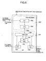
- a media converter (MC) 10 according to a first embodiment of the present invention is connected to a host computer or management switch 20 through 100BASE-TX:UTP cable and to the other host computer or management switch 30 through 100BASE-FX:optical cable. Needless to say, this system is shown just as an example for simplicity.
- the media converter 10 has a pair of ports, which are provided with physical-layer devices (PHYs) 101 and 102, each connected to UTP cable and optical cable, respectively.
- PHYs physical-layer devices
- the physical-layer devices 101 and 102 support MII (Media Independent Interface) conforming to IEEE802.3 standards.
- the media converter 10 is further provided with a FIFO (First-in-first-out) memory 103 that is connected between the physical-layer devices 101 and 102 to absorb frequency deviations between transmission and reception. Data received at one physical-layer device are sequentially written into the FIFO memory 103 and then read out from the FIFO memory 103 in the same sequence to be output to the other physical-layer device.
- FIFO First-in-first-out
- the FIFO memory 103 is connected to a PLD (programmable logic device) 104 that has been programmed to provide a predetermined logical function.
- the PLD 104 as described later, is designed to check data stored in the FIFO memory 103 at a predetermined timing after a packet has been received and, only if the data of the FIFO memory 103 matches predetermined data, to output an enable signal E LB to a microprocessor 105.
- the microprocessor 105 when receiving the enable signal E LB from the PLD 104, generates a predetermined response packet and controls a corresponding physical-layer device to send it as a reply to the received packet back to the source.
- the microprocessor 105 can access internal registers including farEF (far End Fault) register and Force Link register incorporated in the physical-layer devices 101 and 102 according to IEEE802.3-standard MII. Accordingly, link information indicating link establishment status and/or half/full duplex can be acquired from each physical-layer device. Furthermore, it is possible to force the physical-layer device being in link disconnection status into transmittable state by accessing the Force Link register thereof.
- farEF far End Fault
- Force Link register incorporated in the physical-layer devices 101 and 102 according to IEEE802.3-standard MII. Accordingly, link information indicating link establishment status and/or half/full duplex can be acquired from each physical-layer device. Furthermore, it is possible to force the physical-layer device being in link disconnection status into transmittable state by accessing the Force Link register thereof.
- the management switch 20 is provided with a physical-layer device 201 that supports MII (Media Independent Interface) conforming to IEEE802.3 standards, MAC (Media Access Control) layer device 202, and a microprocessor (CPU) 203.
- the physical-layer device 201 is connected to the physical-layer device 101 of the media converter 10 through the UTP cable.
- the microprocessor 203 can access internal registers incorporated in the physical-layer device 201 according to IEEE802.3-standard MII. Accordingly, link information indicating link establishment status can be acquired from the physical-layer device 201. Furthermore, it is possible to force the physical-layer device 201 being in link disconnection status into transmittable state by accessing the Force Link register thereof.
- the management switch 30 has a circuit structure similar to the management switch 20. Its physical-layer device is connected to the physical-layer device 102 of the media converter 10 through the optical cable. The physical-layer device also supports MII (Media Independent Interface) conforming to IEEE802.3 standards.
- MII Media Independent Interface
- the media converter 10 performs only normal media conversion. More specifically, a normal Ethernet packet received from the management switch 20 is converted into optical data by the media converter 10 and the optical data is transmitted to the destination host computer or management switch 30 through the optical cable. Contrarily, normal optical data received from the management switch 30 is converted into normal Ethernet packet by the media converter 10 and the normal Ethernet packet is sent to the management switch 20 through UTP cable.
- the management switch 20 In the case where a response test is activated, the management switch 20 generates a special Ethernet packet including predetermined trigger data (hereafter, called a trigger packet P TRG ) and transmits it to the media converter 10 through the UTP cable.
- a trigger packet P TRG predetermined trigger data
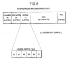
- a trigger packet is composed of 8-byte preamble, 6-byte destination address field, 6-byte source address field, data field of 48-1502 bytes, and 4-byte FCS field.
- predetermined trigger data is written in the source address field.
- the trigger data is preferably unique data such as identification number.
- the ID number assigned to a circuit board incorporated in the media converter 10 is used as the trigger data because the circuit board number is a unique number assigned to the circuit board by the vendor.
- Such a circuit board number is used as the trigger data to generate a trigger packet having the circuit board number stored in the source address field to transmit it to the media converter 10.
- the media converter 10 When receiving a packet having its own circuit board number stored in the source address field thereof, the media converter 10 switches into response test mode and generates a response packet to send it back to the management switch 20. When receiving a packet having data other than its own circuit board number stored in the source address field thereof, the media converter 10 passes the packet as a normal packet through.
- a microprocessor 203 when link disconnection is detected in a management switch 20 (step S301), a microprocessor 203 starts a test program (step S302). In the test mode, the microprocessor 203 generates a trigger packet P TRG having the circuit board number of the media converter 10 written in the source address field thereof, and transmits it to the UTP cable through the physical layer device 201.
- the media converter 10 When the physical layer device 101 receives the trigger packet P TRG , the media converter 10 is switched to the test mode (step S303), and a missing link function is released (Disable) (step S304) and a response packet P RPL is returned through the same physical-layer device 101 to the management switch 20. When a predetermined time has elapsed after the test mode, the media converter 10 returns to the normal mode (step S305).
- the management switch 20 When the management switch 20 receives the specified response packet P RPL , it is determined that the link is normally established. When the management switch 20 does not receive the response packet P RPL within the predetermined time or the response packet P RPL is not the specified one, it is determined that a failure has occurred (step S306).
- Fig. 3 the response test in the normal mode is shown. However, in the case where the link is disconnected due to the missing link function, the similar response test can be also made.
- the test operations in the media converter 10 and management switch 20 in the missing-link mode will be described hereafter.
- the physical-layer devices 101 and 102 are set to be incapable of transmitting but receiving.
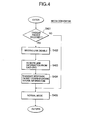
- the PLD 104 checks data stored in the FIFO memory 103 at a predetermined timing after the data has been received to determine whether the data stored in the FIFO memory 103 is the specified trigger data or not (step S401.)
- the trigger data check is performed at the timing of the source address field as shown in Fig. 2.
- the PLD 104 When the specified trigger data is found in the source address field of the received packet (YES at step S401), the PLD 104 outputs the enable signal E LB to the microprocessor 105, and the microprocessor 105 switches its operation mode to the test mode and disables the missing link function (step S402.)
- the microprocessor 105 accesses internal resistors of each physical-layer device to get link information (step S403.)
- the microprocessor 105 accesses the internal resistors of the corresponding physical-layer device 102 to acquire link information of the optic cable side.
- the microprocessor 105 generates a response packet P RPL having the acquired link information written in the source address field thereof, and transmits it from the physical-layer device 101 which has received the trigger packet P TRG , to the source (step S404.) After that, the microprocessor 105 returns to the normal mode (step S405.) When the received packet is not a packet having its own trigger data included therein (No at step S401), the packet is transferred in the normal mode (step S405).
- the management switch 20 cannot know where a failure occurs. For example, the management switch 20 detects only the link disconnection of UTP cable side when the UTP cable is cut or when the media converter 10 enables the missing link function caused by disconnection of the optic cable side. In other words, the management switch 20 cannot discriminate between disconnection caused by the UTP cable cut and disconnection caused by the missing link function.
- the microprocessor 203 when the microprocessor 203 detects the link disconnection of UTP cable side (YES at step S501), the microprocessor 203 accesses the force link register of the physical-layer device 201 to force the physical-layer device 201 into ForceLink Enable status (step S502.)
- the microprocessor 203 When the physical-layer device 201 is switched to the ForceLink Enable status, the microprocessor 203 generates a trigger packet P TRG having the specified number (here, circuit board number) of the media converter 10 written in the source address field, and transmits it through the UTP cable. After the microprocessor 203 releases the ForceLink Disable status (step S504), it returns to the normal mode (step S505) and waits for a corresponding response packet to the trigger packet P TRG to be received for the predetermined time (steps S506, S507 and S508.)
- step S506 When the response packet R PRL is received within in the predetermined time (YES at step S506), the link information of the media converter 10 included in the response packet P PRL is read to analyze (step S507). After the predetermined time has passed (YES at step S508), the judgment based on the received link information is made (step S509.)
- the response packet P PRL was received within the predetermined time, it can be determined that at least the UTP cable and the media converter 10 operates normally and a failure occurs in more distant cable or devices. In this case, it can be determined from the link information included in the response packet P PRL that the failure may occur in the optic cable side.
- response packet P PRL is not received within the predetermined time (NO at step S506 and YES at step S508), it can be determined that the UTP cable and/or the media converter 10 have some failure.
- the media converter according to the first embodiment is automatically switched to the test mode when receiving a predeteremined trigger packet, and a response packet to the trigger packet is sent back to the transmitting side. In this way, the response test can be activated from the cable side.
- the host side forces the physical-layer device into ForceLink enable status to transmit the trigger packet.
- the media converter under the missing link status receives the trigger packet, the media converter disables the missing link function to send the response packet back to the transmitting side. Therefore, when receiving the response packet, the host side can determine that at least the media converter and the link to the media converter operate normally, while when the response packet is not returned, it can be determined that at least one of the media converter and the link has some failure.
- a media converter according to a second embodiment of the present invention will be described in detail hereafter.
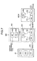
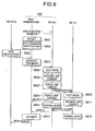
- a media converter 600 is composed of a media converter 601 and a test manager 602 that is connected to the microprocessor 105 of the media converter 601 through a dedicated bus 603. Since the media converter 601 has the substantially same structure as the media converter 10 as shown in Fig. 1 (FIFO memory 103 and PLD 104 are not shown in Fig. 3), circuit blocks similar to those previously described with reference to Fig. 1 are denoted by the same reference numerals and the descriptions will be omitted.
- the test manager 602 includes a microprocessor 604 and a network interface card (NIC) 605.
- the microprocessor 604 is connected to the microprocessor 105 of media converter 301 through the bus 603.
- the network interface card 605 is connected with a network management tool (not shown) through a 10M UTP cable.
- the test manager 602 monitors the link status, instructs test startup, and analyze and judge the collected information.
- the above-described media converter 601 works in a basically same manner as the converter 10, the difference exists in exchanging control signals and data between the microprocessor 105 and the microprocessor 604 of the test manager 602 through the dedicated bus 603.
- the media converter 600 is connected with the management switch 20 through UTP cable UTP1 and with the other media converter 40 through the optic fiber cable FO and the media converter 40 is further connected with UTP cable UTP2.
- the test manager 602 monitors the link status through the media converter 601, and when it detects the link disconnection (step S801), the test manager 602 notifies the network management tool of the link disconnection status (step S802). When the network management tool receives the notification of link disconnection, it instructs the test manager 602 to start the test program (step S803).
- the test manager 302 When instructed by the network management tool, the test manager 302 starts the test mode (step S804) and causes the media converter 601 to switch to the test mode (Step S805). Then, the media converter 601 disables the missing link function (step S806), and switches the physical-layer device 102 to ForceLink Enable status (step S807) to transmit the trigger packet having the unique number of the media converter 40 written in the source address field thereof to the media converter 40. After transmitting the trigger packet, the media convert 601 disables the ForceLink (step S808) and notifies the test manager 602 of the link information. Thereafter, the media converter 601 returns to the normal mode (step S809) and then waits for the corresponding response packet to the trigger packet to be received.
- the media converter 40 when having received the trigger packet from the media converter 601, the media converter 40 is switched to the test mode (step S810) and disables the missing link function to transmit a response packet back to the media converter 601 (step S811). Thereafter, the media converter 40 returns to the normal mode (step S812).
- the media converter 601 receives the response packet from the media converter 40, the media converter 601 reads the link information from the response packet and notifies the test manager 602.
- the test manager 602 analyzes the link information received from the media converters 601 and 40 to judge the location of a failure (step S513), and notifies the network management tool of the test result.
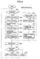
- the microprocessor 105 of media converter 601 disables the missing link function (step S902), and switches the physical layer device 102 to ForceLink Enable status to transmit a trigger packet to the next media converter 40 (step S903). After transmitting the trigger packet addressed to the next media converter 40 (step S904), the microprocessor 105 disables ForceLink status (step S905) and then acquires the link information from each physical layer device (step S906). The microprocessor 105 notifies the test manager 602 of the acquired link information through the dedicated bus 603 (step S907).
- the microprocessor 105 returns to the normal mode (step S908) and waits for the response packet to the transmitted trigger packet to be received (step S909).
- the microprocessor 105 receives the response packet (YES at step S909), it reads the link information stored in the response packet to notify the test manager 602 (step S910).
- the microprocessor 105 receives any packet other than the response packet (NO at step S909), it just transfers it (step S911).
- the microprocessor 105 determines whether the trigger packet has been received or not (step S912).
- the control goes to the step S608.
- the PLD 104 determines whether the data stored in the FIFO memory 103 is the predefined trigger data (the self-identified number) at the predetermined timing. In this case, the content of FIFO memory 103 is checked at the timing of the source address field thereof as shown in Fig. 2. When the trigger data addressed to itself is found in the source address field, it is determined that the trigger packet has been received.
- the microprocessor 105 of media converter 601 disables the missing link function (step S913) and acquires the link information from each physical layer device (step S914). As described above, the microprocessor 105 generates the response packet having the acquired link information written in the predetermined location, and transmits it to the source side of trigger packet (step S915). After transmitting the response packet, the control goes to the step S908.
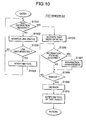
- the microprocessor 604 of the test manager 602 monitors the link status through the microprocessor 105 of media converter 601 (step S1002) and determines whether the link is disconnected or not (step S1003), as long as it is not instructed to start the test from the network management tool (No at step S1001). When the link status is normal (NO at step S1003), steps S1001 and S1002 are repeated until the test startup instruction is received.
- the microprocessor 604 When the microprocessor 604 detects the link disconnection (YES at step S1003), the microprocessor 604 notifies the network management tool of the link disconnection (step S1004) and waits for the test startup instruction to be received from the network management tool.
- the microprocessor 604 When the microprocessor 604 is instructed to start the test by the network management tool (YES at step S1001), it starts the test mode of media converter 601 (step S1005) and waits for link information to be received from media converters (here, MC601 and MC40) within a predetermined time-out period (steps S1006-S1008).
- the microprocessor 604 Upon receipt of link information from a media converter (YES at step S1006), the microprocessor 604 arranges the link information (step S1007) and, after an elapse of the predetermined time, determines a test result based on the acquired link information (step S1009). For example, if the microprocessor 604 does not acquire link information from the media converter 40 within the predetermined time but from the media converter 601, it can be determined that a failure occurs in the media converter 40 or the optic fiber cable connected between the media converters 601 and 40. In the case where the microprocessor 604 receives the notification within the predetermined time from both media converters 601 and 40, it can be determined from the link information received from the media converter 40 whether a failure occurs on the UTP cable UTP2 (see Fig. 7). The test manager 602 notifies the network management tool of the test result (step S1010).
- test control of the media converter 40 is similar to that of the media converter 10 as shown in Fig. 4. Therefore, the details will be omitted.
- FIG. 11 Another embodiment of the media converter with test manager is shown in Fig. 11.
- the test manager 302 manages each of the media converters MC 1 to MC N as described above.
- failure detection can be made based on their response packets. Particularly, when the response packet has not been received from a certain media converter within the predetermined time, it can be determined that a failure has occurred in more distant from this media converter. Therefore, the occurrence of a failure in a link including media converters can be easily detected and the location of the failure can be specified to some extent.
- Each media converter can discriminate a trigger packet addressed thereto from other trigger packets and normal packets. Accordingly, the test mode can be activated by receiving the trigger packet and the response packet in response to the trigger packet can be sent back to the source. Therefore the link test can be started from cable side and it can be verified by receiving the response packet that not only the link reach this media converter but this media converter itself are normally operating.
- each media converter receives any trigger packet other than the trigger packet addressed thereto in the status of missing link, the media converter is switched to the normal mode to pass this received packet through. Therefore, since a packet which does not target this media converter for the response test is passed through, the link test can be performed more distant from there.
- the test mode when a link disconnection is detected, the test mode is started to transmit the trigger packet and can perform the failure detection test by receiving the response packet. Since no additional function to a management switch is required, the system structure becomes simplified.
Landscapes
- Engineering & Computer Science (AREA)
- Computer Networks & Wireless Communication (AREA)
- Signal Processing (AREA)
- Computer Security & Cryptography (AREA)
- Maintenance And Management Of Digital Transmission (AREA)
Applications Claiming Priority (4)
| Application Number | Priority Date | Filing Date | Title |
|---|---|---|---|
| JP2001056485A JP3485312B2 (ja) | 2001-03-01 | 2001-03-01 | メディアコンバータおよびその制御方法 |
| JP2001056485 | 2001-03-01 | ||
| JP2001056484 | 2001-03-01 | ||
| JP2001056484A JP3459046B2 (ja) | 2001-03-01 | 2001-03-01 | テストマネージャ付きメディアコンバータ、障害検出システムおよび障害検出方法 |
Publications (1)
| Publication Number | Publication Date |
|---|---|
| EP1237336A2 true EP1237336A2 (de) | 2002-09-04 |
Family
ID=26610419
Family Applications (1)
| Application Number | Title | Priority Date | Filing Date |
|---|---|---|---|
| EP01113666A Withdrawn EP1237336A2 (de) | 2001-03-01 | 2001-06-19 | Medienumsetzer und verbindungstest-technik mit einem solchen Medienumsetzer |
Country Status (5)
| Country | Link |
|---|---|
| US (1) | US20020124110A1 (de) |
| EP (1) | EP1237336A2 (de) |
| KR (1) | KR100676116B1 (de) |
| SG (1) | SG116425A1 (de) |
| TW (1) | TW513868B (de) |
Cited By (1)
| Publication number | Priority date | Publication date | Assignee | Title |
|---|---|---|---|---|
| CN100579039C (zh) * | 2003-08-19 | 2010-01-06 | 索尼德国有限责任公司 | 一种用于无线家庭联网系统的射频覆盖扩展的方法及系统 |
Families Citing this family (24)
| Publication number | Priority date | Publication date | Assignee | Title |
|---|---|---|---|---|
| JP4554101B2 (ja) * | 2001-02-28 | 2010-09-29 | 株式会社フジクラ | ローカル情報伝送機能内蔵メディアコンバータおよび障害警報信号伝送方式 |
| US6839872B2 (en) * | 2001-05-28 | 2005-01-04 | Allied Telesis Kabushiki Kaisha | Media converter and failure detection technique |
| WO2003055144A1 (en) * | 2001-12-20 | 2003-07-03 | Allied Telesis K.K. | Communication system, communication system managing method, relay device, relay device control method, program, and recorded medium |
| US7005861B1 (en) | 2002-06-07 | 2006-02-28 | Marvell International Ltd. | Cable tester |
| US6980007B1 (en) | 2002-06-07 | 2005-12-27 | Marvell International Ltd. | Cable tester with insertion loss and return loss estimators |
| US7358745B1 (en) * | 2002-06-07 | 2008-04-15 | Marvell International Ltd. | Cable tester |
| US7173431B1 (en) | 2002-06-07 | 2007-02-06 | Marvell International Ltd. | Cable tester |
| US7075283B1 (en) | 2002-06-07 | 2006-07-11 | Marvell International Ltd. | Cable tester |
| US7002353B1 (en) * | 2002-06-07 | 2006-02-21 | Marvell International, Ltd. | Cable tester |
| US7019533B1 (en) | 2002-06-07 | 2006-03-28 | Marvell International Ltd. | Cable tester |
| US7375532B1 (en) | 2002-06-07 | 2008-05-20 | Marvell International Ltd. | Cable tester |
| US7679371B1 (en) | 2005-05-27 | 2010-03-16 | Marvell International Ltd. | Advanced time domain reflection cable testing |
| US7680925B2 (en) * | 2006-01-24 | 2010-03-16 | Cisco Technology, Inc. | Method and system for testing provisioned services in a network |
| US7688749B1 (en) | 2006-04-03 | 2010-03-30 | Marvell International Ltd. | Network interface with autonegotiation and cable length measurement |
| US8553720B2 (en) * | 2006-04-19 | 2013-10-08 | Marvell World Trade Ltd. | Adaptive speed control for MAC-PHY interfaces |
| US7906973B1 (en) | 2006-06-09 | 2011-03-15 | Marvell International Ltd. | Cable tester |
| US7804784B1 (en) | 2006-08-28 | 2010-09-28 | Marvell International Ltd. | Cable tester |
| US7808249B1 (en) | 2007-02-22 | 2010-10-05 | Marvell International Ltd. | Methods and apparatus for measuring a length of a cable |
| US7808247B1 (en) | 2007-02-22 | 2010-10-05 | Marvel International Ltd. | Fast cable tester |
| US8243752B2 (en) | 2007-04-04 | 2012-08-14 | Marvell World Trade Ltd. | Long-reach ethernet for 1000BASE-T and 10GBASE-T |
| CN102474677B (zh) * | 2009-09-09 | 2016-06-08 | 美国博通公司 | 基于同轴电缆的以太网无源光网络(epoc) |
| KR101091161B1 (ko) | 2009-11-11 | 2011-12-09 | 주식회사 제노코 | 이더넷 mii를 이용한 랜덤 에러 주입 장치 |
| US9749211B2 (en) * | 2011-02-15 | 2017-08-29 | Entit Software Llc | Detecting network-application service failures |
| CA3088402C (en) * | 2018-01-23 | 2024-03-19 | Cable Television Laboratories, Inc. | Systems and methods for a universal data link with demodulation and modulation only processing at intermediate nodes |
Family Cites Families (6)
| Publication number | Priority date | Publication date | Assignee | Title |
|---|---|---|---|---|
| US5619550A (en) * | 1993-09-23 | 1997-04-08 | Motorola, Inc. | Testing within communication systems using an arq protocol |
| US5673254A (en) * | 1995-06-07 | 1997-09-30 | Advanced Micro Devices Inc. | Enhancements to 802.3 media access control and associated signaling schemes for ethernet switching |
| US6067585A (en) * | 1997-06-23 | 2000-05-23 | Compaq Computer Corporation | Adaptive interface controller that can operate with segments of different protocol and transmission rates in a single integrated device |
| US6480477B1 (en) * | 1997-10-14 | 2002-11-12 | Innowave Eci Wireless Systems Ltd. | Method and apparatus for a data transmission rate of multiples of 100 MBPS in a terminal for a wireless metropolitan area network |
| US6516352B1 (en) * | 1998-08-17 | 2003-02-04 | Intel Corporation | Network interface system and method for dynamically switching between different physical layer devices |
| US6795450B1 (en) * | 2000-09-28 | 2004-09-21 | Tdk Semiconductor Corporation | Method and apparatus for supporting physical layer link-suspend operation between network nodes |
-
2001
- 2001-05-04 US US09/848,432 patent/US20020124110A1/en not_active Abandoned
- 2001-06-19 EP EP01113666A patent/EP1237336A2/de not_active Withdrawn
- 2001-08-17 TW TW090120225A patent/TW513868B/zh not_active IP Right Cessation
- 2001-08-27 SG SG200105212A patent/SG116425A1/en unknown
- 2001-09-10 KR KR1020010055596A patent/KR100676116B1/ko not_active Expired - Fee Related
Cited By (1)
| Publication number | Priority date | Publication date | Assignee | Title |
|---|---|---|---|---|
| CN100579039C (zh) * | 2003-08-19 | 2010-01-06 | 索尼德国有限责任公司 | 一种用于无线家庭联网系统的射频覆盖扩展的方法及系统 |
Also Published As
| Publication number | Publication date |
|---|---|
| KR100676116B1 (ko) | 2007-02-01 |
| US20020124110A1 (en) | 2002-09-05 |
| KR20020071698A (ko) | 2002-09-13 |
| SG116425A1 (en) | 2005-11-28 |
| TW513868B (en) | 2002-12-11 |
Similar Documents
| Publication | Publication Date | Title |
|---|---|---|
| EP1237336A2 (de) | Medienumsetzer und verbindungstest-technik mit einem solchen Medienumsetzer | |
| US6839872B2 (en) | Media converter and failure detection technique | |
| US6314476B1 (en) | Network adapter enabling bidirectional monitoring of a terminal device between a computer and a managing device | |
| JP4437984B2 (ja) | ネットワーク中継装置及びその制御方法 | |
| US6122248A (en) | Data transmission system with bus failure recovery | |
| JP3857317B2 (ja) | 自動交渉の進捗モニタ | |
| US20030021281A1 (en) | Media converter and transmission system using the same | |
| JPH03154452A (ja) | プロトコル・システム、動的結合装置のポートの状態を制御するための方法、動的スイッチ及び双方向伝送システムを動作させるための方法 | |
| KR100300905B1 (ko) | 네트워크 시스템 | |
| EP1148679B1 (de) | Datenübertragungsverfahren | |
| JP2008536412A (ja) | ユーザ端末、マスタ・ユニット、通信システムおよびその稼動方法 | |
| WO2009144843A1 (ja) | 通信システム、試験装置、通信装置、通信方法および試験方法 | |
| CN100566277C (zh) | 通信网络系统和用于传送信息的方法 | |
| JP3485312B2 (ja) | メディアコンバータおよびその制御方法 | |
| JP3753950B2 (ja) | メディアコンバータおよびそのテストモード起動方法 | |
| JP3459046B2 (ja) | テストマネージャ付きメディアコンバータ、障害検出システムおよび障害検出方法 | |
| JP2003037600A (ja) | テストマネージャ付きメディアコンバータ、障害検出方法、およびそれを用いたシステム | |
| JP3796415B2 (ja) | メディアコンバータ、障害検出システムおよび障害検出方法 | |
| KR20050072637A (ko) | 이더넷 시스템에서의 정보 획득장치 및 방법 | |
| JP2004032029A (ja) | ネットワーク処理装置及び設定方法 | |
| JP2009060418A (ja) | ネットワーク障害検知方法、データ通信ネットワークシステムおよびノード装置 | |
| JP4253085B2 (ja) | Lan間接続装置 | |
| KR100733971B1 (ko) | 결함허용 전이중방식 분산제어시스템 | |
| JP2004328624A (ja) | データ通信装置及び方法 | |
| JPH0340618A (ja) | バス型ネットワークの二重化方式 |
Legal Events
| Date | Code | Title | Description |
|---|---|---|---|
| PUAI | Public reference made under article 153(3) epc to a published international application that has entered the european phase |
Free format text: ORIGINAL CODE: 0009012 |
|
| AK | Designated contracting states |
Kind code of ref document: A2 Designated state(s): AT BE CH CY DE DK ES FI FR GB GR IE IT LI LU MC NL PT SE TR |
|
| AX | Request for extension of the european patent |
Free format text: AL;LT;LV;MK;RO;SI |
|
| STAA | Information on the status of an ep patent application or granted ep patent |
Free format text: STATUS: THE APPLICATION IS DEEMED TO BE WITHDRAWN |
|
| 18D | Application deemed to be withdrawn |
Effective date: 20050104 |