EP1237310A2 - Verfahren und Vorrichtung zum Testen einer Basisstation in einem CDMA Kommunikationssystem - Google Patents
Verfahren und Vorrichtung zum Testen einer Basisstation in einem CDMA Kommunikationssystem Download PDFInfo
- Publication number
- EP1237310A2 EP1237310A2 EP02004248A EP02004248A EP1237310A2 EP 1237310 A2 EP1237310 A2 EP 1237310A2 EP 02004248 A EP02004248 A EP 02004248A EP 02004248 A EP02004248 A EP 02004248A EP 1237310 A2 EP1237310 A2 EP 1237310A2
- Authority
- EP
- European Patent Office
- Prior art keywords
- sector
- attenuation
- mobile terminal
- internal mobile
- attenuator
- Prior art date
- Legal status (The legal status is an assumption and is not a legal conclusion. Google has not performed a legal analysis and makes no representation as to the accuracy of the status listed.)
- Withdrawn
Links
Images


Classifications
-
- H—ELECTRICITY
- H04—ELECTRIC COMMUNICATION TECHNIQUE
- H04W—WIRELESS COMMUNICATION NETWORKS
- H04W24/00—Supervisory, monitoring or testing arrangements
- H04W24/06—Testing, supervising or monitoring using simulated traffic
-
- H—ELECTRICITY
- H04—ELECTRIC COMMUNICATION TECHNIQUE
- H04W—WIRELESS COMMUNICATION NETWORKS
- H04W24/00—Supervisory, monitoring or testing arrangements
-
- H—ELECTRICITY
- H04—ELECTRIC COMMUNICATION TECHNIQUE
- H04B—TRANSMISSION
- H04B17/00—Monitoring; Testing
- H04B17/10—Monitoring; Testing of transmitters
- H04B17/15—Performance testing
- H04B17/191—Over-the-air testing
-
- H—ELECTRICITY
- H04—ELECTRIC COMMUNICATION TECHNIQUE
- H04W—WIRELESS COMMUNICATION NETWORKS
- H04W16/00—Network planning, e.g. coverage or traffic planning tools; Network deployment, e.g. resource partitioning or cells structures
- H04W16/22—Traffic simulation tools or models
-
- H—ELECTRICITY
- H04—ELECTRIC COMMUNICATION TECHNIQUE
- H04W—WIRELESS COMMUNICATION NETWORKS
- H04W88/00—Devices specially adapted for wireless communication networks, e.g. terminals, base stations or access point devices
- H04W88/08—Access point devices
-
- H—ELECTRICITY
- H04—ELECTRIC COMMUNICATION TECHNIQUE
- H04W—WIRELESS COMMUNICATION NETWORKS
- H04W36/00—Hand-off or reselection arrangements
- H04W36/16—Performing reselection for specific purposes
- H04W36/18—Performing reselection for specific purposes for allowing seamless reselection, e.g. soft reselection
Definitions
- This invention relates to a base station testing apparatus (may be simply called a base testing apparatus) and a base station testing method each of which is used in a CDMA (Code Division Multiple Access) system, and, in particular, to the base station testing apparatus and the base station testing method which can realize a softer handover test between selected ones of sectors in a service area assigned to a base transceiver station (BTS).
- a base station testing apparatus may be simply called a base testing apparatus
- a base station testing method each of which is used in a CDMA (Code Division Multiple Access) system
- CDMA Code Division Multiple Access
- a mobile communication system is structured by a great number of mobile terminals and a plurality of base transceiver stations (BTS) communicable with the mobile terminals through radio channels within service areas assigned to the respective BTS.
- BTS base transceiver stations
- Such base transceiver stations will be often simply called base stations hereinafter.
- the mobile communication system has a base station controller (BSC), a mobile radio exchange operable as an upper device, and a public telephone network.
- BSC base station controller
- Such a base transceiver station namely, BTS
- BTS has a service area or cell divided into three or six sectors and a plurality of directive antennas each of which has directivity covering each sector.
- each directive antenna exhibits no directivity on the rear of each antenna and therefore serves to reliably divide each cell. This makes it possible to repeatedly utilize the same radio wave resources in a plurality of the BTS and therefore to accommodate a great number of subscribers in each BTS.
- similar base stations have been provided which have a plurality of antennas directed to sectors.
- each bas station should be tested in an active or operation state so as to make sure of whether or not the base station in question is operated in a normal state.
- a conventional base station testing apparatus has been used to execute an operational test of confirming a normal operation in each base station.
- the base station testing apparatus may be often referred to as a test transmitter receiver (TTR) hereinafter.
- TTR test transmitter receiver
- the operational test is carried out by the conventional base station testing apparatus at every one of the sectors.
- no consideration is made in such a conventional base station testing apparatus about testing a handover operation which switches the sectors from one to another as a mobile terminal is moved from one sector to another and which will be called a softer handover operation.
- EP1022872 A2 (will be simply called Reference) corresponding to Japanese Unexamined Patent Publication No.2000-224119, disclosure is made about an apparatus that includes a multi-channel attenuator coupled to a plurality of cell sectors, a field data processor, and a mobile in a lab.
- the field data processor is operable to convert field test data into time-varying attenuator control values while the multi-channel attenuator is operable to respond to the attenuator control values for each channel.
- the mobile in the lab can observe carrier and interference levels and might serve to test and optimize handoff procedures between cell sectors.
- the apparatus disclosed in Reference is used in the lab and is operable to virtually recreate radio frequency conditions, such as a variable RF loss, of a cellular network from previously generated field test data.
- the disclosed apparatus is effective to virtually test the RF loss along forward and reverse attenuation paths before a base station is actually deployed in a cellular network.
- BTS base transceiver station
- a base testing apparatus is for use in a CDMA communication system in combination with an active base transceiver station that has a plurality of sector transceivers corresponding to a plurality of sectors in a service area, respectively.
- the base station testing apparatus has an internal mobile terminal placed therein and comprises first means for individually adjusting degrees of coupling between the internal mobile terminal and each of the transceivers, respectively, and second means, coupled to the first means, for reproducing a softer handover test of the sector transceivers between two adjacent ones of the sectors by controlling the degrees of coupling between the internal mobile terminal and each sector transceiver through the first means.
- the degrees of coupling are defined by attenuation values and the first means comprises a plurality of pre-set attenuators which are made to correspond to the transceivers in the BTS and each of which provides at least three attenuation values different from one another.
- each of the pre-set attenuators provides, as at least three attenuation values, a first attenuation value, a second attenuation value smaller than the first attenuation value, and a third attenuation value smaller than the second attenuation value.
- the first attenuation value gives an optimum call connection state between the internal mobile terminal and the sector transceiver of the corresponding sector while the second and the third attenuation values give a call connection start enable state between the internal mobile terminal and the sector transceiver of the corresponding sector and a call disconnection state between the internal mobile terminal and the sector transceiver of the corresponding sector, respectively.
- the first, the second, and the third attenuation values are equal to 0 dB, -3 dB, and -50 dB, respectively.
- each of the pre-set attenuators comprises a first attenuator terminal given a switching control signal from the second means, a second attenuator terminal connected to the sector transceiver of the corresponding sector, a third attenuator terminal coupled to the internal mobile terminal, a plurality of attenuator units having attenuation values different from each other, a plurality of switches for selectively connecting the attenuator units between the second and the third attenuator terminals in response to drive signals to provide the first, the second, and the third attenuation values, and a drive control circuit for controlling on/off control of the respective switches in response to the switching control signal sent through the first attenuator terminal.
- the attenuator units are equal in number to two and provides the attenuation values of -3 dB and - 47 dB, respectively.
- each of the pre-set attenuators further comprises a plurality of ⁇ /2 strip lines which are connected in common to an intersection point connected to the third attenuation terminal and which are also connected to the switches for selectively connecting the ⁇ /2 strip lines to the second attenuation terminal through the attenuation units selected.
- the second means comprises setting means for setting a sector number assigned to each sector to indicate a sector and control means for controlling the degrees of coupling in the first means to reproduce the softer handover test so that the degrees of coupling are selected from a first degree of coupling between the internal mobile terminal and the sector transceiver of the indicated sector, a second degree of coupling between the internal mobile terminal and an adjacent sector transceiver of an adjacent sector to the indicated sector, and a third degree of coupling between the internal mobile terminal and the remaining sector transmitters.
- the second means further reproduces the softer handover test by executing a call connection test between two radio paths between the internal mobile terminal and the indicated sector and between the internal mobile terminal and the adjacent sector.
- the radio path between the internal mobile terminal and the indicated sector transceiver is kept at the first attenuation value while the other radio path between the internal mobile terminal and the adjacent sector transceiver is kept at the second attenuation value and the remaining radio paths are kept at the third attenuation value.
- the second means further executes another call connection test of the radio path between the internal mobile terminal and the indicated sector transceiver before the call connection test of the two radio paths and a further call connection test of another radio path between the internal mobile path and the adjacent sector transceiver after the call connection test of the two radio paths.
- each of the call connection test of the radio path or the radio paths monitors a power control time interval in consideration of the softer handover operation.
- a method is for use in testing an active base transceiver station (BTS) in a CDMA communication system.
- the active base transceiver station has a plurality of sector transceivers corresponding to a plurality of sectors in a service area, respectively.
- the method is executed by the use of an internal mobile terminal and comprises the steps of individually adjusting degrees of coupling between the internal mobile terminal and each of the transceivers, respectively, and reproducing a softer handover test of the sector transceivers between two adjacent ones of the sectors by controlling the degrees of coupling between the internal mobile terminal and each sector transceiver through the first means.
- the degrees of coupling are defined by attenuation values and the adjusting step comprises the step of using a plurality of pre-set attenuators which are made to correspond to the transceivers in the BTS and each of which provides at least three attenuation values different from one another.
- Each of the pre-set attenuators provides, as at least three attenuation values, a first attenuation value, a second attenuation value smaller than the first attenuation value, and a third attenuation value smaller than the second attenuation value.
- the adjusting step comprises the steps of giving the first attenuation value in an optimum call connection state between the internal mobile terminal and the sector transceiver of the corresponding sector and giving the second and the third attenuation values in a call connection start enable state between the internal mobile terminal and the sector transceiver of the corresponding sector and in a call disconnection state between the internal mobile terminal and the sector transceiver of the corresponding sector, respectively.
- the reproducing step comprises the steps of setting a sector number assigned to each sector to indicate a sector and controlling the degrees of coupling in the first means to reproduce the softer handover test so that the degrees of coupling are selected from a first degree of coupling between the internal mobile terminal and the sector transceiver of the indicated sector, a second degree of coupling between the internal mobile terminal and an adjacent sector transceiver of an adjacent sector to the indicated sector, and a third degree of coupling between the internal mobile terminal and the remaining sector transmitters.
- the degrees of coupling are defined by attenuation values and the first degree of coupling is defined by a first attenuation value while the second degree is defined by a second attenuation value smaller than the first attenuation value and the third degree is defined by a third attenuation value smaller than the second attenuation value.
- the reproducing step comprises the step of executing a call connection test between two radio paths between the internal mobile terminal and the indicated sector and between the internal mobile terminal and the adjacent sector.
- the executing step comprises the steps of keeping the radio path between the internal mobile terminal and the indicated sector transceiver at the first attenuation value, keeping the other radio path between the internal mobile terminal and the adjacent sector transceiver at the second attenuation value, and keeping the remaining radio paths at the third attenuation value.
- the reproducing step comprises the steps of executing another call connection test of the radio path between the internal mobile terminal and the indicated sector transceiver before the call connection test of the two radio paths and executing a further call connection test of another radio path between the internal mobile path and the adjacent sector transceiver after the call connection test of the two radio paths.
- each of the call connection test of the radio path or the radio paths monitors a power control time interval in consideration of the softer handover operation.
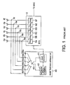
- the illustrated conventional base testing apparatus 40 is coupled to an active base station 2 which may be called a base transceiver station (BTS) and which is connected to a base station controller (BSC in Fig. 1) (not shown).
- BTS base transceiver station
- BSC base station controller
- the conventional base testing apparatus is operable to execute an operational test for confirming whether or not the BTS 2 is normal in operation. It is assumed that the BTS 2 has a service area divided into six sectors.
- the BTS 2 is specified by first through sixth transmitter receivers (TRXa to TRXf) which are connected through feeders to first through sixth sector antennas 4a to 4f, respectively, and which transmit and receive radio signals to and from the respective sector antennas 4a to 4f.
- TRXa to TRXf transmitter receivers
- the base testing apparatus 40 is coupled to the first through the sixth sector antennas 4a to 4f through first through sixth couplers 6a to 6f, respectively, and serves to execute the operational test at every sector.
- the illustrated base testing apparatus 40 has first through sixth antenna input terminals 44a to 44f given transmission and reception signals of the TRXa to TRXf included in the BTS 2 and a sector selection switch 43 selectively connected to the first through the sixth antenna input terminals 44a to 44f.
- the sector selection switch 43 is operable in response to a switching signal sent from a controller 41 and serves to switch the sector selection switch 43 to selectively send the transmission and the reception signals of the TRXa to TRXf to an internal mobile terminal 42 under control of the controller 41. With this structure, the transmission and the reception signals are switched at every one of the sectors by the sector selection switch 43 and delivered to the internal mobile terminal 42.
- the controller 41 is supplied from the BTS 2 with a test indication signal.
- the internal mobile terminal 42 is connected to each of the TRXa to TRXF one by one on testing the BTS 2 and, in this situation, transmission and reception tests are carried out between the base testing apparatus 40 and the BTS 2. Accordingly, the transmission and the reception tests should be repeated six times in order to test the first through the sixth TRXa to TRXf.
- this base testing apparatus 40 it is possible to determine whether or not each TRX assigned to each sector in the BTS 2 is normal. However, it is impossible for the conventional base testing apparatus to test a handover operation executed in the CDMA system to switch the sectors from one to another. Herein, such a handover operation executed in the CDMA system to switch the sectors from one to another will be referred to as a softer handover operation, as mentioned before.
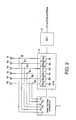
- a base testing apparatus 1 is connected to a base transceiver station (BTS) 2 in a manner similar to that illustrated in Fig. 1, as shown in Fig. 2.
- BTS base transceiver station
- the BTS 2 is also connected to a base station controller (BSC) 3 coupled to any other upper system, such as a network (not shown).
- BSC base station controller
- the illustrated BTS 2 has first through sixth TRXa to TRXf connected through sector antenna feeders to first through sixth sector antennas 4a to 4f, respectively. Between the first through the sixth sector antennas 4a to 4f and the first through the sixth TRXa to TRXf, first through sixth couplers 6a to 6f are placed.
- the first through the sixth couplers 6a to 6f have input and output terminals that are loosely coupled to the respective sector antenna feeders and that are coupled to the base testing apparatus 1 to supply the same with radio signals used for testing. Such radio signals are transmitted from and received by the base testing apparatus 1.
- the base testing apparatus 1 illustrated in Fig. 2 has first through sixth antenna input/output terminals 7a to 7f connected to the first through the sixth sector antennas 4a to 4f through the first through the sixth couplers 6a to 6f, respectively.
- the base testing apparatus 1 is coupled to the first through the sixth TRXa to TRXf of the BTS 2 via the first through the sixth antenna input/output terminals 7a to 7f.
- the illustrated base testing apparatus is connected to the BTS 2 to transmit/receive various kinds of control information and call information to and from the BTS 2.
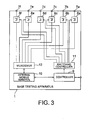
- the base testing apparatus has first through sixth pre-set attenuators 8a to 8f, a controller 9, an internal mobile terminal 10, a switching controller 11, and a multiplexer /demultiplexer (abbreviated to MUX/DEMUX) 12.
- the first through sixth pre-set attenuators 8a to 8f are operable to adjust degrees of coupling between the internal mobile terminal 10 and the first through sixth TRXa to TRXf, respectively, and may be called a first circuit element.
- the degrees of coupling are defined by attenuation values in the illustrated example.
- the controller 9 receives a control signal from the BTS so as to control the base testing apparatus 1 and transmits a response signal from the base testing apparatus 10 to the BTS 2. Responsive to the control signal, the controller 9 controls the switching controller 11 by producing an internal control signal so as to adjust the first through the sixth pre-set attenuators 8a to 8f in a manner to be described later in detail. Responsive to a switching control signal delivered from the switching controller 11, each of the first through the sixth pre-set attenuators 8a to 8f can control a degree of coupling between the internal mobile terminal 10 and each of the TRXa to TRXf of the BTS 2 (illustrated in Fig. 1). At any rate, a combination of the controller 9 and the switching controller 11 may serve to reproduce a softer handover of the active base transceiver station (BTS) 2 in a manner to be described later in detail and may be named a second circuit element.
- BTS active base transceiver station
- the first through the sixth pre-set attenuators 8a to 8f are connected to the multiplexer/demultiplexer (MUX/DEMUX) 12.
- the multiplexer/demultiplexer 12 serves to receive first through sixth attenuator output signals from the first through the sixth pre-set attenuators 7a to 7f to be combined into a combined signal and to deliver or distribute a mobile output signal from the internal mobile terminal 10 to the first through the sixth pre-set attenuators 7a to 7f.
- the first through the sixth atternuator output signals may be collectively called a down link radio signal from the BTS 2 towards the internal mobile terminal 10 and are controlled by the first through the sixth pre-set attenuators 7a to 7f.
- the mobile output signal may be called an up link radio signal from the internal mobile terminal 10 towards the BTS 2 and is divided by the multiplexer/demultiplexer 12 to be sent to the first through the sixth pre-set attenuators 7a to 7f as first through sixth attenuator input signals s 7a to 7f.
- the internal mobile terminal 10 can execute a call control test of the BTS 2 by sending the mobile output signal to the multiplexer/demultiplexer 12 and by receiving the down link radio signal from the multiplexer/demultiplexer 12.
- the controller 9 Supplied with the control signal from the BTS 2, the controller 9 sends an internal control signal to the switching controller 11. Furthermore, the controller 9 carries out a call control operation by transmitting and receiving various call control signals to and from the internal mobile terminal 10.
- the controller 9 executes a selection control operation for selecting the pre-set attenuators 8a to 8f and an attenuation set operation for setting an attenuation value of each selected attenuator 8a to 8f.
- the internal control signal is sent from the controller 9 to the switching controller 11 to be distributed as the switching control signal to each pre-set attenuator 8a to 8f.
- each of the first through the sixth pre-set attenuators 8a to 8f is similar in structure and operation and is therefore represented by the first pre-set attenuator 8a in Fig. 4.
- the pre-set attenuator 8a has a first attenuator terminal 36 connected to the switching controller 11 (Fig. 3), a second attenuator terminal 37 connected to the antenna input/output terminal 7a (Fig. 3), and a third attenuator termninal 38 connected to the multiplexer/demultiplexer 12 (Fig. 3).
- the illustrated pre-set attenuator 8a comprises first and second switches 26 and 27 that are connected to the second attenuator terminal 37 on one hand and that are connected to a ⁇ /2 strip line 35 and a 3 dB attenuator unit 28, respectively, on the other hand.
- the 3 dB attenuator unit 28 is connected to the second switch 27 at one end, as mentioned above, and is also connected to third and fourth switches 29 and 30 at another end.
- the third switch 29 is connected to the third attenuator terminal 38 through a ⁇ /2 strip line 34 while the fourth switch 30 is connected to a 47 dB attenuator unit 31 which is also connected to a fifth switch 32.
- the fifth switch 32 is connected to the third attenuator terminal 38 through a ⁇ /2 strip line 33.
- the ⁇ /2 strip line 35, the ⁇ /2 strip line 34, and the ⁇ /2 strip line 33 are connected in common to the third attenuator terminal 38 through an intersection point 39, as shown in Fig. 4, and have lengths adjusted to half wavelengths of pass band radio frequencies, respectively.
- the first through the fifth switches 26, 27, 29, 30, and 32 are controlled by first through fifth switch drivers 21 to 24, respectively, that are connected to a driver controller 20.
- the driver controller 20 is connected to the first attenuator terminal 36 and is supplied with the internal control signal from the controller 9 (Fig. 3) through the switching controller 11.
- the first through the fifth switch drivers 21 to 25 are selectively put into active states when they are selected by selection signals sent from the driver controller 20.
- the first through the fifth switch drivers 21 to 25 serve to execute on/off control operations of the first through the fifth switches 26, 27, 29, 30, and 32, respectively.
- the ⁇ /2 strip lines 25, 34, and 33 are connected through the first, the third, and the fifth switches 26, 29, and 32, the intersection point 39, and the third attenuator terminal 38.
- the ⁇ /2 strip lines 35, 34, and 33 are put into off states for the pass band radio frequencies and are disconnected from the first, the third, and the fifth switches 26, 29, and 32. In this situation, it is possible to suppress a variation of a radio characteristic.
- the first, the third, and the fifth switch drivers 21 to 25 are controlled by the driver controller 20 so that a selected one of the first, the third, and the fifth switches 26, 29, and 32 alone is turned on with the remaining two switches are turned off to connect only one of the ⁇ /2 strip lines 35, 34, and 33 to the third attenuator terminal 38 through the intersection point 39.
- the illustrated pre-set attenuator 8a is operable in response to the switching control signal sent from the switching controller 11 (Fig. 3) through the first attenuator terminal 36. Supplied with the switching control signal, the pre-set attenuator 8a basically controls attenuation between the second and the third attenuator terminals 37 and 38 to set an attenuation value in an optimum call connection state, to set an attenuation value in a call start enable state, and to set an attenuation value in a call disconnection state.
- the attenuation in the optimum call connection state may be 0 dB while the attenuation in each of the call start enable state and the call disconnection state may be set to -3dB and -50 dB, respectively.
- the states of 0 dB and - 50 dB can be realized by putting the pre-set attenuator 8a into the on and off states and represent connection and disconnection states of the pre-set attenuator 8a, respectively.
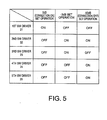
- Fig. 5 Referring to Fig. 5 along with Fig. 4, description will be made about 0 dB set operation, -3 dB set operation, and -50 dB set operation of the pre-set attenuator 8a (Fig. 4). As shown in Fig. 5, the above-mentioned operations of setting the attenuation can be realized by on/off control operations of the first through the fifth switch drivers 21 to 25.
- the first switch driver 21 supplies the first switch 26 with a drive signal to put the first switch 26 into the on state.
- a drive signal may be referred to as an on signal, as shown in Fig. 5.
- the second, the third, and the fifth switch drivers 22, 23, and 25 are kept off so as to put the second, the third, and the fifth switches 27, 29, and 32 into off states, respectively, as shown in Fig. 5.
- the second and the third attenuator terminals 37 and 38 are connected through the ⁇ /2 strip line 35 and the first switch 26 alone without any attenuator units, such as 28 and 31.
- the 0 dB set operation may be named a first test.
- the -3 dB set operation is carried out in the manner tabulated in Fig. 5.
- the -3 dB attenuator unit 28 is connected between the second and the third attenuator terminals 37 and 38.
- the second and the third switch drivers 22 and 23 sends the drive signal to the second and the third switches 27 and 29 to put them into the on states, respectively, as exemplified in Fig. 5, on the -3 dB set operation.
- the second and the third attenuator terminals 37 and 38 are connected through the ⁇ /2 strip line 34, the third switch 29, the -3dB attenuator unit 28, and the second switch 27.
- -3dB attenuation is accomplished by the -3 dB set operation that will be called a second test.
- the -50 dB set operation is carried out in a manner as exemplified in Fig.5, so as to accomplish -50 dB attenuation between the second and the third attenuator terminals 37 and 38.
- both the - 3dB attenuator unit 28 and the -47 dB attenuator unit 31 are connected between the second and the third attenuator terminals 37 and 38.
- the second, the fourth, and the fifth switches 27, 30, and 32 are turned on in response to the drive signal sent from the second, the fourth, and the fifth switch drivers 22, 24, and 25, as tabulated in Fig. 5.
- the -50 dB set operation serves to provide attenuation of -50 dB and may be called a third test.
- a test sector number is determined at a step 100 by the controller 9 (Fig. 2) indicated by the BTS 2.
- the controller 9 either one of the first through the sixth sectors is set by the controller 9 (Fig. 3) as the test sector number assigned to the determined sector.
- the test sector number is sent from the controller 9 as the internal control signal to the switching controller 11 to be delivered as the switching control signals to the first through the sixth pre-set attenuators 8a to 8f (Fig. 3).
- the pre-set attenuator indicated by the test sector number may be referred to as a test pre-set attenuator and is set into the connection state while the other pre-set attenuators are left into the disconnection states.
- the test sector is given 0 dB while the remaining sectors are given -50 dB.
- the test sector and the corresponding pre-set attenuator are put into the connection state while the other or remaining sectors and the corresponding pre-set attenuators are put into the disconnection states, as shown at a step 101.
- the pre-set attenuator of the test sector is controlled by the switching controller 11 to carry out the 0 dB set operation, as mentioned in conjunction with Figs. 4 and 5 while the other pre-set attenuators are put into the disconnection states by providing the -50 dB attenuation in the manner described with reference to Figs. 4 and 5.
- a time interval of 200ms is timed by the controller 9 at a step 102.
- the call connection is executed between the internal mobile terminal 10 of the base testing apparatus 1 and the TRX of the BTS 2 corresponding to the test sector to test whether or not the test sector is normal (step 103). As a result, it is confirmed whether or not the test sector is normally connected.
- the operation of the steps 101 to 103 correspond to the first test mentioned above. In other words, the first test is at first executed at the steps 101 to 103.
- the step 103 is followed by a step 104 at which a softer handover connection is executed with the test sector unchanged.
- a step 104 at which a softer handover connection is executed with the test sector unchanged.
- the pre-set attenuator of the adjacent sector is set or changed from -50 dB attenuation to -3dB attenuation while the pre-set attenuation of the test sector is kept in the connection state of 0dB.
- the remaining pre-set attenuators of the other sectors are kept in the disconnection state of -50dB, as shown at a step 104 in Fig. 6.
- the softer handover connections are established at the step 104 by setting the pre-set attenuators of the test and the adjacent sectors to the above-mentioned situations.
- the internal mobile terminal 10 of the base testing apparatus 1 automatically establishes two radio paths between the internal mobile terminal 10 and the test sector TRX and between the internal mobile terminal 10 and the adjacent sector TRX.
- a time interval of 200ms is timed at a step 105 that is followed by a step 106.
- the call connection is tested so as to make sure of whether or not the call connection is normally kept without interruption through two radio paths between the internal mobile terminal 10 and the test sector TRX and between the internal mobile terminal 10 and the adjacent sector TRX.
- the second test is executed at the steps 104 to 106.
- the pre-set attenuator of the test sector is switched from 0 dB to -50dB in a manner as mentioned with reference to Fig. 4 and put into the disconnection state or off state.
- the pre-set attenuator of the adjacent sector is set from -3dB to 0dB to be put into the connection state or on state while the other pre-set attenuators of the other sectors are kept at - 50dB and put into the disconnection state.
- the radio path between the internal mobile station 10 and the test sector TRX of the BTS 2 is disconnected while only the radio path between the internal mobile station 10 and the adjacent sector TRX is kept connected.
- a time interval of 200ms is timed at a step 108 like the steps 102 and 105.
- the connection between the internal mobile terminal 10 and the adjacent sector TRX of the BTS 2 is checked at a step 109 about whether or not the call connection is kept normal without any interruption.
- the steps 107 to 109 serve to execute the third test.
- the softer handover test is finished in connection with a single test sector. Thereafter, test conditions set in the base testing apparatus 1 and the BTS 2 are cleared at a step 110 in order to continue the softer handover test in a similar manner. Subsequently, it is judged at a step 111 whether or not the softer handover test is finished about all of the sectors. If any other test sectors are left without being tested, a next following test sector number is set at a step 112 to be returned back to the step 101. Otherwise, the softer handover test is completed.
- the steps illustrated in Fig. 6 are executed under control of the controller 9 (Fig. 3) cooperating with the active BTS 2.
- the above-mentioned base testing apparatus 1 serves to test an actual softer handover in cooperation with the active BTS 2.
- time interval of 200ms are timed at the steps 102, 105, and 108.
- Such a time interval is helpful to maintain a sufficient movement time and a suitable power control time for the softer handover operation and, as a result, to stabilize the operation of the BTS 2. It is noted that such movement time and power control times are varied in dependency upon a variation of the radio paths.
- the base testing apparatus has a plurality of pre-set attenuators which are controllable and each of which is placed between the internal mobile terminal and each TRX correponding to each sector.
- Each pre-set attenuator is varied in attenuation among three attenuation values, namely, 0 dB, -3 dB, and -50 dB.
- the attenuation value of 0 dB defines an optimum connection state while the attenuation values of -3dB and -50dB define a call start enable state and a call disconnection state, respectively.
- the softer handover test is executed by simulating the softer handover state by the use of the three kinds of attenuation values.
- this invention is advantageous in that a stable softer handover test is executed by setting the sufficient time interval when the radio paths are changed from one to two or from two to one.
- each of the pre-set attenuators may be varied among four or more kinds of attenuation values.
- the sector number may not be restricted to three or six.
- each pre-set attenuator may include a wide variety of attenuator units besides the -3 dB attenuator unit and the -47 dB attenuator unit.
- a -50 dB attenuator unit may be used instead of the -47 dB attenuator unit.
Landscapes
- Engineering & Computer Science (AREA)
- Computer Networks & Wireless Communication (AREA)
- Signal Processing (AREA)
- Physics & Mathematics (AREA)
- Electromagnetism (AREA)
- Mobile Radio Communication Systems (AREA)
- Monitoring And Testing Of Transmission In General (AREA)
Applications Claiming Priority (2)
| Application Number | Priority Date | Filing Date | Title |
|---|---|---|---|
| JP2001050343A JP3516663B2 (ja) | 2001-02-26 | 2001-02-26 | Cdma基地局試験装置及び基地局試験方法 |
| JP2001050343 | 2001-02-26 |
Publications (2)
| Publication Number | Publication Date |
|---|---|
| EP1237310A2 true EP1237310A2 (de) | 2002-09-04 |
| EP1237310A3 EP1237310A3 (de) | 2005-10-05 |
Family
ID=18911314
Family Applications (1)
| Application Number | Title | Priority Date | Filing Date |
|---|---|---|---|
| EP20020004248 Withdrawn EP1237310A3 (de) | 2001-02-26 | 2002-02-26 | Verfahren und Vorrichtung zum Testen einer Basisstation in einem CDMA Kommunikationssystem |
Country Status (6)
| Country | Link |
|---|---|
| US (1) | US20020119772A1 (de) |
| EP (1) | EP1237310A3 (de) |
| JP (1) | JP3516663B2 (de) |
| KR (1) | KR20020069498A (de) |
| CN (1) | CN1372397A (de) |
| BR (1) | BR0201728A (de) |
Cited By (2)
| Publication number | Priority date | Publication date | Assignee | Title |
|---|---|---|---|---|
| EP1496630A3 (de) * | 2003-07-07 | 2005-02-02 | Samsung Electronics Co., Ltd. | Gerät und Verfahren zur Diversity-Prüfung einer Basisstation in einem Mobilkommunikationssystem |
| WO2006004462A1 (en) * | 2004-06-30 | 2006-01-12 | Telefonaktiebolaget Lm Ericsson (Publ) | Data processing in intra-site handover |
Families Citing this family (27)
| Publication number | Priority date | Publication date | Assignee | Title |
|---|---|---|---|---|
| DE19947654A1 (de) * | 1999-10-04 | 2001-04-12 | Deutsche Telekom Mobil | Koppfelfeld für Hochfrequenzsignale |
| US7065352B2 (en) * | 2002-09-13 | 2006-06-20 | Cingular Wireless Ii, Llc | System and method for improved spectrum use |
| US7200393B2 (en) * | 2002-09-13 | 2007-04-03 | Cingular Wireless Ii, Llc | System for split transmission for enhanced spectrum utilization |
| US7242930B2 (en) * | 2002-09-13 | 2007-07-10 | Cingular Wireless Ii, Llc | System and method for increasing transmission capability |
| RU2353060C2 (ru) * | 2003-01-30 | 2009-04-20 | Квэлкомм Инкорпорейтед | Запускаемый событием сбор данных |
| JP4475423B2 (ja) | 2003-04-14 | 2010-06-09 | 日本電気株式会社 | ハンドオーバー機能試験方法及びスペクトラム拡散移動通信システム |
| CN101159895B (zh) * | 2003-05-20 | 2010-09-29 | 华为技术有限公司 | 一种基站实现方法 |
| US7542769B1 (en) * | 2003-06-30 | 2009-06-02 | Nortel Networks Limited | Dynamic control of eighth-rate gating of the reverse link fundamental channel in a wireless communication system |
| JP4299641B2 (ja) * | 2003-11-17 | 2009-07-22 | 株式会社日立コミュニケーションテクノロジー | 無線基地局試験方法及び試験装置 |
| US7353020B2 (en) * | 2003-11-17 | 2008-04-01 | Hitachi Communication Technologies, Ltd. | Radio access point testing apparatus and method of testing radio access point |
| US8457552B1 (en) | 2004-01-20 | 2013-06-04 | Qualcomm Incorporated | Method and apparatus for reduced complexity short range wireless communication system |
| US8219076B2 (en) * | 2004-07-20 | 2012-07-10 | Nortel Networks Limited | CDMA probe for self-testing base station receivers |
| US7907908B2 (en) * | 2004-08-04 | 2011-03-15 | Hitachi, Ltd. | Radio access point testing apparatus and method of testing radio access point |
| CN100382626C (zh) * | 2004-10-27 | 2008-04-16 | 中兴通讯股份有限公司 | 一种移动通讯基站测试系统 |
| US7684464B2 (en) | 2004-12-21 | 2010-03-23 | Qualcomm Incorporated | Method and apparatus for performing channel assessment in a wireless communication system |
| CN100428826C (zh) * | 2006-02-17 | 2008-10-22 | 华为技术有限公司 | 一种软切换、更软切换成功率的统计方法 |
| CN101080084B (zh) * | 2006-05-24 | 2010-05-26 | 鸿富锦精密工业(深圳)有限公司 | 漫游功能测试系统、装置及方法 |
| KR100790333B1 (ko) * | 2007-01-29 | 2008-01-02 | 주식회사 이노와이어리스 | 핸드오버 테스트기능을 갖는 휴대인터넷 계측기 |
| CN101159956B (zh) * | 2007-10-29 | 2011-08-10 | 中兴通讯股份有限公司 | 通讯系统的模拟切换装置及切换方法 |
| CN101860405B (zh) * | 2010-05-14 | 2013-12-18 | 上海电信工程有限公司 | 积木式宽带adsl/epon/lan开通测试维护模块及方法 |
| CN102395151A (zh) * | 2011-06-29 | 2012-03-28 | 中兴通讯股份有限公司 | 一种移动终端切换测试方法、系统和装置 |
| CN103096359B (zh) * | 2011-11-04 | 2016-11-23 | 华为技术有限公司 | 诊断馈线接错的方法及装置 |
| US10506454B2 (en) * | 2012-07-31 | 2019-12-10 | Dali Systems Co., Ltd. | Optimization of traffic load in a distributed antenna system |
| CN103118405B (zh) * | 2013-03-19 | 2015-05-20 | 大唐移动通信设备有限公司 | Ue在小区间移动的测试系统及测试方法 |
| KR101657444B1 (ko) | 2015-05-13 | 2016-09-20 | 주식회사 이노와이어리스 | 모바일 핸드 오버 테스트 시스템 |
| US10237754B1 (en) * | 2017-05-12 | 2019-03-19 | Sprint Spectrum L.P. | Minimizing interference in different sectors of wireless networks |
| CN111431633B (zh) * | 2020-03-17 | 2022-06-21 | Oppo(重庆)智能科技有限公司 | 测试方法和系统,及存储介质 |
Family Cites Families (11)
| Publication number | Priority date | Publication date | Assignee | Title |
|---|---|---|---|---|
| US5465393A (en) * | 1993-04-12 | 1995-11-07 | Telefonaktiebolaget Lm Ericsson | Simulated air interface system for simulating radio communication |
| KR100202502B1 (ko) * | 1996-12-30 | 1999-06-15 | 정장호 | 이동통신시스템 기지국의 시험회로 |
| US6900775B2 (en) * | 1997-03-03 | 2005-05-31 | Celletra Ltd. | Active antenna array configuration and control for cellular communication systems |
| US6154638A (en) * | 1998-01-16 | 2000-11-28 | Lucent Technologies Inc. | Methods and apparatus for determining forward and reverse link performance in a wireless communication system |
| US6766164B1 (en) * | 1999-01-19 | 2004-07-20 | Lucent Technologies Inc. | System and method for providing radio frequency conditions for testing wireless communications equipment |
| US6272337B1 (en) * | 1999-05-17 | 2001-08-07 | Nortel Networks Limited | Testing a mobile communications system |
| KR100303304B1 (ko) * | 1999-08-11 | 2001-11-01 | 윤종용 | 차세대 코드분할다중접속 이동전화망시스템의 핸드오프 수행상태 테스트 장치 및 그 방법 |
| KR20010019997A (ko) * | 1999-08-31 | 2001-03-15 | 박종섭 | 아이엠티-2000 시스템에서의 광대역 씨디엠에이 신호용 채널 시뮬레이터 |
| US6687500B1 (en) * | 1999-09-21 | 2004-02-03 | Dave Causey | System for testing soft handoff functionality of a mobile station used for a code division multiple access (CDMA) mobile communication system |
| KR100316746B1 (ko) * | 1999-11-29 | 2001-12-12 | 오길록 | 코드분할다중접속 이동통신 시스템의 성능 분석을 위한무선채널 모사시험방법 및 장치 |
| JP3366315B2 (ja) * | 2000-03-06 | 2003-01-14 | 埼玉日本電気株式会社 | 無線基地局試験装置 |
-
2001
- 2001-02-26 JP JP2001050343A patent/JP3516663B2/ja not_active Expired - Fee Related
-
2002
- 2002-02-25 US US10/081,191 patent/US20020119772A1/en not_active Abandoned
- 2002-02-26 CN CN02106509A patent/CN1372397A/zh active Pending
- 2002-02-26 EP EP20020004248 patent/EP1237310A3/de not_active Withdrawn
- 2002-02-26 KR KR1020020010140A patent/KR20020069498A/ko not_active Ceased
- 2002-02-26 BR BR0201728A patent/BR0201728A/pt not_active IP Right Cessation
Cited By (6)
| Publication number | Priority date | Publication date | Assignee | Title |
|---|---|---|---|---|
| EP1496630A3 (de) * | 2003-07-07 | 2005-02-02 | Samsung Electronics Co., Ltd. | Gerät und Verfahren zur Diversity-Prüfung einer Basisstation in einem Mobilkommunikationssystem |
| US7433684B2 (en) | 2003-07-07 | 2008-10-07 | Samsung Electronics Co., Ltd | Apparatus and method for verifying diversity of a base station in a mobile communication system |
| WO2006004462A1 (en) * | 2004-06-30 | 2006-01-12 | Telefonaktiebolaget Lm Ericsson (Publ) | Data processing in intra-site handover |
| US8374607B2 (en) | 2004-06-30 | 2013-02-12 | Telefonaktiebolaget Lm Ericsson (Publ) | Data processing in intra-site handover |
| US8706121B2 (en) | 2004-06-30 | 2014-04-22 | Unwired Planet, Llc | Data processing in intra-site handover |
| US9072019B2 (en) | 2004-06-30 | 2015-06-30 | Unwired Planet, Llc | Data processing in intra-site handover |
Also Published As
| Publication number | Publication date |
|---|---|
| BR0201728A (pt) | 2003-06-10 |
| KR20020069498A (ko) | 2002-09-04 |
| EP1237310A3 (de) | 2005-10-05 |
| US20020119772A1 (en) | 2002-08-29 |
| JP2002252588A (ja) | 2002-09-06 |
| CN1372397A (zh) | 2002-10-02 |
| JP3516663B2 (ja) | 2004-04-05 |
Similar Documents
| Publication | Publication Date | Title |
|---|---|---|
| EP1237310A2 (de) | Verfahren und Vorrichtung zum Testen einer Basisstation in einem CDMA Kommunikationssystem | |
| JP3913696B2 (ja) | 基地局装置 | |
| US8229497B2 (en) | Distributed antenna communications system | |
| JP4283867B2 (ja) | ハンドオーバ方法及びセルラー通信システム | |
| CN101842995B (zh) | 用于配置分布式天线通信系统的系统和方法 | |
| EP0667086B1 (de) | Funksystem | |
| US6192216B1 (en) | Remotely controlled gain control of transceiver used to inter-connect wireless telephones to a broadband network | |
| AU712159B2 (en) | A handover method, and a cellular radio system | |
| US5465393A (en) | Simulated air interface system for simulating radio communication | |
| EP2063676B1 (de) | Mobiles-Endgerät-Simulator für ein drahtloses Kommunikationsnetz | |
| US20100040161A1 (en) | Wireless telecommunication system, transmitter and receiver | |
| JPH04347937A (ja) | 無線アンテナ切換装置 | |
| KR100391403B1 (ko) | Cdma 방식을 이용한 무선 통신 시스템 | |
| GB2306083A (en) | TDMA communication system | |
| JPH09289500A (ja) | Tdma通信方法および装置 | |
| EP1503521A1 (de) | Mobilkommunikationsvorrichtung | |
| JP3699064B2 (ja) | 無線基地局試験システムと無線基地局試験方法 | |
| KR0125479B1 (ko) | 셀룰라 기지국 시험장치 | |
| KR20030089713A (ko) | 이동기 시험 시스템 및 커플링 | |
| JP3162956B2 (ja) | ダイバーシチ装置 | |
| JP3133646B2 (ja) | ダイバーシチ装置 | |
| US6011972A (en) | Technique for setting cell coverage | |
| JP2000049688A (ja) | 無線基地局における消費電力制御方法及びその方式 | |
| KR0125480B1 (ko) | 개선된 전파경로를 갖는 셀룰라 기지국 시험장치 | |
| JP2003234685A (ja) | 無線基地局装置の試験方法および試験システム並びに試験装置 |
Legal Events
| Date | Code | Title | Description |
|---|---|---|---|
| PUAI | Public reference made under article 153(3) epc to a published international application that has entered the european phase |
Free format text: ORIGINAL CODE: 0009012 |
|
| AK | Designated contracting states |
Kind code of ref document: A2 Designated state(s): AT BE CH CY DE DK ES FI FR GB GR IE IT LI LU MC NL PT SE TR |
|
| AX | Request for extension of the european patent |
Free format text: AL;LT;LV;MK;RO;SI |
|
| PUAL | Search report despatched |
Free format text: ORIGINAL CODE: 0009013 |
|
| AK | Designated contracting states |
Kind code of ref document: A3 Designated state(s): AT BE CH CY DE DK ES FI FR GB GR IE IT LI LU MC NL PT SE TR |
|
| AX | Request for extension of the european patent |
Extension state: AL LT LV MK RO SI |
|
| 17P | Request for examination filed |
Effective date: 20050824 |
|
| AKX | Designation fees paid |
Designated state(s): DE GB |
|
| STAA | Information on the status of an ep patent application or granted ep patent |
Free format text: STATUS: THE APPLICATION HAS BEEN WITHDRAWN |
|
| 18W | Application withdrawn |
Effective date: 20061006 |