EP1237255A1 - Motorgehäuse - Google Patents
Motorgehäuse Download PDFInfo
- Publication number
- EP1237255A1 EP1237255A1 EP02251060A EP02251060A EP1237255A1 EP 1237255 A1 EP1237255 A1 EP 1237255A1 EP 02251060 A EP02251060 A EP 02251060A EP 02251060 A EP02251060 A EP 02251060A EP 1237255 A1 EP1237255 A1 EP 1237255A1
- Authority
- EP
- European Patent Office
- Prior art keywords
- housing
- finger
- end cap
- ridge
- engagement portion
- Prior art date
- Legal status (The legal status is an assumption and is not a legal conclusion. Google has not performed a legal analysis and makes no representation as to the accuracy of the status listed.)
- Granted
Links
Images
Classifications
-
- H—ELECTRICITY
- H02—GENERATION; CONVERSION OR DISTRIBUTION OF ELECTRIC POWER
- H02K—DYNAMO-ELECTRIC MACHINES
- H02K5/00—Casings; Enclosures; Supports
- H02K5/04—Casings or enclosures characterised by the shape, form or construction thereof
- H02K5/15—Mounting arrangements for bearing-shields or end plates
Definitions
- This invention relates to miniature electric motors and in particular, to the housing for a miniature motor.
- Miniature motors vary in size and with small miniature motors, the material of the rear housing part is relatively thin, allowing an end cap or bearing plate to be secured to the rear housing by crimping the rear housing. This crimping process may involve bending over an axially extending finger cut from the edge of the rear housing or simply deforming discrete parts of the edge of the rear housing.
- the metal also exhibits resilience so that when the cut finger crimping method is used with a thick wall housing, say in the order of 2 mm, the finger springs back slightly. While the end cap is still captured by the finger, it is not held firmly against the metal housing resulting in play or movement between the metal housing and the end cap.
- Another method used is to cut holes in the housing so as to form pairs of opposing circumferentially extending fingers. Sometimes the fingers may be joined together.
- the end plate is crimped to the housing by radially deforming the fingers over a crimping surface of the end cap thereby preventing axial separation of the end cap and the housing.
- connection is not affected by spring back of the metal fingers, the degree of tightness of the connection will depend on the relative dimensions of the end cap and housing crimping portions. For this reason, such connections are used mostly with metal end plates. If the end plate thickness is too small or the fingers are too narrow then there will be a gap between the end plate and the finger giving a loose connection between the end plate and the housing. If the end plate is too thick or high and/or the fingers are too broad, then the crimping will not be successful, excess force may be applied damaging the motor or the fingers may be deformed leading to possible damage or mounting and handling problems, as well as possible clamping relaxation problems.
- the present invention provides a miniature electric motor comprising: a tubular housing; and at least one end cap, said end cap having a boss portion fitted inside the housing, a flange which abuts an axial end of the housing, and an engagement portion; said housing having at least one circumferentially extending finger which is radially deformed into contact with the engagement portion of the end cap to capture the end cap to the housing; wherein the engagement portion includes an axially projecting ridge and the finger bears axially onto the ridge to nip the end cap to the housing.
- the present invention provides a method of connecting an end cap to a tubular housing of a miniature electric motor, the method comprising the steps of providing an end cap with a flange portion, a boss portion and at least one engagement portion, providing a tubular housing with at least one circumferentially extending finger, inserting the boss portion of the end cap into the housing such that the flange abuts an axial end of the housing and the recess is aligned with the finger, and providing an axially projecting ridge on the engagement portion and deforming the finger radially so that an axially inner edge of the finger axially engages the ridge to prevent axial movement of the end cap with respect to the housing.
- the method also includes providing two pairs of said fingers and radially deforming each pair of fingers into a respective engagement portion of the end cap, each finger having an axially inner edge which extends at an incline to a plane orthogonal to an axis of the housing, the axially inner edge being brought into contact with an axially inner surface of the recess by radially deforming and continuing to radially deform the finger causing the inner edge of the finger to exert an axial force on the surface of the end cap to clamp the end cap to the housing.
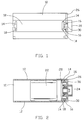
- the housing 10 is a tubular body of electrical steel which may be rolled or deep drawn.
- the housing has a substantially circular cross-section with two flat sides 12. At each end of each flat side, a T-shaped hole 14 is formed producing a pair of circumferentially extending fingers 16.
- the fingers 16 have a tapered axially inner edge 18. These fingers 16 are used to secure an end cap 20 to the housing.
- the housing 10 supports permanent magnets 22 forming the stator field for a motor.
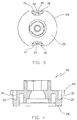
- the end cap 20 has a flange 26 which sits on the end of the housing as well as a boss portion 28 which fits inside the housing 10 and extends axially beyond the T-shaped holes 14.
- Two recesses 30 in the flange 26 and boss 28 are aligned with the pairs of fingers 16 and the fingers 16 are radially deformed into the recesses to secure the end cap to the housing.
- Each recess 30 has a circumferentially extending axially projecting outer lip or ridge 32 which is engaged by the fingers 16. Indeed, the fingers 16 may deform or partly destroy the ridge 32 when they are pressed into the recess 30. As the fingers engage the ridge, the tapered edge 18 of the fingers 16 apply an axial force pressing the end cap into tight contact with the housing. The more the fingers 16 are pressed radially, the greater the axial force applied to the end cap 20. Thus, even if there is slight springback of the fingers 16 in the radial direction, the axial clamping force will remain resulting in no loosening of the end cap.
- the use of the ridge 32 allows for slight variation in axial alignment between the fingers 16 and the recesses 30 due to manufacturing tolerances, etc. without affecting the holding force.
- the ridge 32 can be readily sheared radially by the fingers 16 while providing a strong axial abutment, the area behind the ridge providing a debris collection zone whereby the sheared portion of the ridge does not interfere with the radial deformation of the fingers.
- end caps can be made from metal, either cast or stamped and such end caps can be formed with ridges in the engagement regions which are equivalent to recesses in the moulded end caps. While it is acknowledged that resin can be sheared more easily than metal, particularly mild steel, the ridge can nevertheless be deformed to accommodate the locking fingers and can achieve a good clamping pressure or resiliency.
- the ridge can be used with straight sided fingers to give satisfactory results by shearing or deforming the ridge.
- a chamfer on the ridge goes some way to increase the clamping force for a straight edged finger but is also beneficial for tapered fingers.
- the present invention provides a very effective yet simple method of securely clamping an end cap to a housing of an electric motor even when the housing has a relatively thick wall making axial crimping impractical.
- the fingers are shown formed in pairs, they could be formed individually. Also while two pairs of fingers are shown for holding one end cap, arrangements can be envisaged where there is only one finger or one pair of fingers is required to secure the end cap. Alternatively, three, four or more fingers or pairs of fingers could be used.
Landscapes
- Engineering & Computer Science (AREA)
- Power Engineering (AREA)
- Motor Or Generator Frames (AREA)
Applications Claiming Priority (2)
| Application Number | Priority Date | Filing Date | Title |
|---|---|---|---|
| GB0104212 | 2001-02-21 | ||
| GBGB0104212.6A GB0104212D0 (en) | 2001-02-21 | 2001-02-21 | Motor casing |
Publications (2)
| Publication Number | Publication Date |
|---|---|
| EP1237255A1 true EP1237255A1 (de) | 2002-09-04 |
| EP1237255B1 EP1237255B1 (de) | 2004-01-21 |
Family
ID=9909165
Family Applications (1)
| Application Number | Title | Priority Date | Filing Date |
|---|---|---|---|
| EP02251060A Expired - Lifetime EP1237255B1 (de) | 2001-02-21 | 2002-02-15 | Motorgehäuse |
Country Status (6)
| Country | Link |
|---|---|
| US (1) | US6700254B2 (de) |
| EP (1) | EP1237255B1 (de) |
| CN (1) | CN1248389C (de) |
| DE (1) | DE60200172T2 (de) |
| ES (1) | ES2214463T3 (de) |
| GB (1) | GB0104212D0 (de) |
Cited By (2)
| Publication number | Priority date | Publication date | Assignee | Title |
|---|---|---|---|---|
| DE102009010085B3 (de) * | 2009-02-24 | 2010-07-01 | Saia-Burgess Dresden Gmbh | Linear-Aktuator |
| EP3125408A1 (de) * | 2015-07-30 | 2017-02-01 | Siemens Aktiengesellschaft | Rotierende maschine mit einer verbindungsvorrichtung an gehäuseabschnitten, sowie deren verwendung für diese |
Families Citing this family (18)
| Publication number | Priority date | Publication date | Assignee | Title |
|---|---|---|---|---|
| KR100461739B1 (ko) * | 2002-10-14 | 2004-12-16 | 주식회사 에스 피 지 | 기어드 모터의 하우징 구조 |
| DE502005003461D1 (de) * | 2005-05-11 | 2008-05-08 | Vdo Automotive Ag | Elektrische Maschine mit Abstützung des Rotors auf einer Stirnseite des Stators |
| DE102006026593B4 (de) | 2006-05-31 | 2010-04-08 | Getrag Getriebe-Und Zahnradfabrik Hermann Hagenmeyer Gmbh & Cie Kg | Elektrische Synchronmaschine |
| CN100529349C (zh) * | 2007-09-19 | 2009-08-19 | 无锡开普动力有限公司 | 一种具有排放通道的风冷发电机组端罩组件 |
| JP2009240068A (ja) * | 2008-03-27 | 2009-10-15 | Mabuchi Motor Co Ltd | ケース蓋固定構成を有するモータ |
| CN101877509A (zh) * | 2009-04-29 | 2010-11-03 | 鸿富锦精密工业(深圳)有限公司 | 音圈马达防电磁干扰外壳结构 |
| JP2013138545A (ja) * | 2011-12-28 | 2013-07-11 | Nisca Corp | モータ |
| CN103670894A (zh) * | 2012-09-20 | 2014-03-26 | 江苏恒威机械制造有限公司 | 液压马达端盖强化连接结构 |
| CN202978514U (zh) * | 2012-11-29 | 2013-06-05 | 中山大洋电机制造有限公司 | 一种电机端盖与机壳的装配结构 |
| JP2015136285A (ja) * | 2013-12-17 | 2015-07-27 | パナソニックIpマネジメント株式会社 | 交流整流子電動機、電動送風機及び電動送風機を備える電気機器 |
| CN104295372B (zh) * | 2014-10-15 | 2016-10-05 | 福建永强力加动力设备有限公司 | 发电机组后装饰板 |
| WO2016155271A1 (zh) | 2015-03-31 | 2016-10-06 | 中山大洋电机股份有限公司 | 一种直流无刷电机 |
| CN204858809U (zh) * | 2015-08-15 | 2015-12-09 | 中山大洋电机股份有限公司 | 一种直流无刷电机 |
| EP3453101B1 (de) * | 2016-05-04 | 2021-01-13 | Brose Fahrzeugteile SE & Co. Kommanditgesellschaft, Würzburg | Verfahren zur herstellung eines polgehäuses |
| US11088587B2 (en) * | 2016-10-26 | 2021-08-10 | Nidec Sankyo Corporation | Motor |
| ES2883248T3 (es) * | 2016-11-11 | 2021-12-07 | Agie Charmilles Sa | Motor de eje lineal |
| CN111600455A (zh) * | 2019-02-21 | 2020-08-28 | 三赢科技(深圳)有限公司 | 音圈马达及应用其的摄像头模组和电子装置 |
| TWI883361B (zh) * | 2022-12-15 | 2025-05-11 | 恆達智能科技股份有限公司 | 複合式馬達外殼構造及其製造方法 |
Citations (3)
| Publication number | Priority date | Publication date | Assignee | Title |
|---|---|---|---|---|
| EP0305915A1 (de) * | 1987-09-04 | 1989-03-08 | Licentia Patent-Verwaltungs-GmbH | Elektromotor geringer Leistung |
| FR2723491A1 (fr) * | 1994-08-04 | 1996-02-09 | Valeo Systemes Dessuyage | Machine tournante a paliers exterieurs |
| FR2726700A1 (fr) * | 1994-11-07 | 1996-05-10 | Valeo Systemes Dessuyage | Moteur electrique a collecteur dans lequel les charbons sont cales de facon fiable par rapport aux poles du stator |
Family Cites Families (9)
| Publication number | Priority date | Publication date | Assignee | Title |
|---|---|---|---|---|
| US2701318A (en) * | 1952-11-22 | 1955-02-01 | Gen Electric | Dynamoelectric machine casing |
| US3732616A (en) * | 1968-06-26 | 1973-05-15 | Universal Electric Co | Method of making end frame structures for electric motors |
| US3567973A (en) | 1968-06-26 | 1971-03-02 | Universal Electric Co | Electric motors |
| BE758737A (fr) | 1969-11-11 | 1971-04-16 | Gutris Giorgio | Methode pour le montage de moteurs electriques, et moteurs montes seloncette methode |
| US3600615A (en) * | 1970-01-19 | 1971-08-17 | Tarou Morita | Miniature motor |
| DE3302532A1 (de) | 1983-01-26 | 1984-07-26 | SWF-Spezialfabrik für Autozubehör Gustav Rau GmbH, 7120 Bietigheim-Bissingen | Gehaeuse, insbesondere fuer einen elektromotor, und verfahren zu dessen herstellung |
| US4644204A (en) * | 1985-12-06 | 1987-02-17 | Fasco Industries, Inc. | Motor housing and end shield mount |
| JPH0615501Y2 (ja) * | 1988-07-15 | 1994-04-20 | アスモ株式会社 | 小型モータ |
| DE4138705C2 (de) | 1991-11-26 | 1994-12-15 | Licentia Gmbh | Gehäuse, insbesondere für elektrische Kleinmaschinen |
-
2001
- 2001-02-21 GB GBGB0104212.6A patent/GB0104212D0/en not_active Ceased
-
2002
- 2002-02-15 DE DE2002600172 patent/DE60200172T2/de not_active Expired - Lifetime
- 2002-02-15 EP EP02251060A patent/EP1237255B1/de not_active Expired - Lifetime
- 2002-02-15 ES ES02251060T patent/ES2214463T3/es not_active Expired - Lifetime
- 2002-02-20 US US10/077,974 patent/US6700254B2/en not_active Expired - Lifetime
- 2002-02-21 CN CN02108490.4A patent/CN1248389C/zh not_active Expired - Lifetime
Patent Citations (3)
| Publication number | Priority date | Publication date | Assignee | Title |
|---|---|---|---|---|
| EP0305915A1 (de) * | 1987-09-04 | 1989-03-08 | Licentia Patent-Verwaltungs-GmbH | Elektromotor geringer Leistung |
| FR2723491A1 (fr) * | 1994-08-04 | 1996-02-09 | Valeo Systemes Dessuyage | Machine tournante a paliers exterieurs |
| FR2726700A1 (fr) * | 1994-11-07 | 1996-05-10 | Valeo Systemes Dessuyage | Moteur electrique a collecteur dans lequel les charbons sont cales de facon fiable par rapport aux poles du stator |
Cited By (4)
| Publication number | Priority date | Publication date | Assignee | Title |
|---|---|---|---|---|
| DE102009010085B3 (de) * | 2009-02-24 | 2010-07-01 | Saia-Burgess Dresden Gmbh | Linear-Aktuator |
| US8227949B2 (en) | 2009-02-24 | 2012-07-24 | Saia-Burgess Dresden Gmbh | Linear actuator |
| EP2221948A3 (de) * | 2009-02-24 | 2017-03-29 | Saia-Burgess Dresden GmbH | Linear-Aktuator |
| EP3125408A1 (de) * | 2015-07-30 | 2017-02-01 | Siemens Aktiengesellschaft | Rotierende maschine mit einer verbindungsvorrichtung an gehäuseabschnitten, sowie deren verwendung für diese |
Also Published As
| Publication number | Publication date |
|---|---|
| DE60200172T2 (de) | 2004-11-18 |
| US6700254B2 (en) | 2004-03-02 |
| ES2214463T3 (es) | 2004-09-16 |
| US20020113506A1 (en) | 2002-08-22 |
| EP1237255B1 (de) | 2004-01-21 |
| GB0104212D0 (en) | 2001-04-11 |
| CN1248389C (zh) | 2006-03-29 |
| CN1373545A (zh) | 2002-10-09 |
| DE60200172D1 (de) | 2004-02-26 |
Similar Documents
| Publication | Publication Date | Title |
|---|---|---|
| US6700254B2 (en) | Motor casing | |
| JP4730415B2 (ja) | L型同軸コネクタ | |
| EP2433338B1 (de) | Wasserverschlussstopfen und konnektor mit dem wasserverschlussstopfen | |
| US7576461B2 (en) | Electric motor | |
| EP0917247A1 (de) | Kupplungsvorrichtung für ein Ende eines Koaxialkabels | |
| JP2001251795A (ja) | 永久磁石回転子 | |
| EP2020702A2 (de) | Anschlussende | |
| JP3390721B2 (ja) | C形コンプライアントコンタクト | |
| CN109980370B (zh) | 连接器 | |
| JPH05284677A (ja) | 回転電機のステータコア | |
| US11196202B2 (en) | Electrical connector and electronic device | |
| US6482034B2 (en) | Connection structure for electric wire and terminal, connection method therefor and terminal connecting apparatus | |
| WO2005053108A1 (en) | Electrical terminal | |
| EP1124306A2 (de) | Bürstenhalteranordnung | |
| JPH0759301A (ja) | ブラシ保持板及びそれを備えた電動モーター | |
| JPH05219668A (ja) | 永久磁石式回転子 | |
| JP3140353B2 (ja) | 可動コネクタ | |
| JPH0946946A (ja) | 磁石回転子 | |
| JP2003051351A (ja) | 雄型コンタクト及びその製造方法 | |
| US6594882B1 (en) | Motor manufacturing method using single plate for yoke | |
| JPH11234940A (ja) | 電動機用固定子 | |
| JP3710667B2 (ja) | 回転電機のマグネットカバー固定構造 | |
| JP3531660B2 (ja) | 積層鉄心のカシメ構造 | |
| JPH10302857A (ja) | 電気コネクタ | |
| JPH06105505A (ja) | 磁石回転子の製造方法 |
Legal Events
| Date | Code | Title | Description |
|---|---|---|---|
| PUAI | Public reference made under article 153(3) epc to a published international application that has entered the european phase |
Free format text: ORIGINAL CODE: 0009012 |
|
| AK | Designated contracting states |
Kind code of ref document: A1 Designated state(s): AT BE CH CY DE DK ES FI FR GB GR IE IT LI LU MC NL PT SE TR |
|
| AX | Request for extension of the european patent |
Free format text: AL;LT;LV;MK;RO;SI |
|
| 17P | Request for examination filed |
Effective date: 20030124 |
|
| AKX | Designation fees paid |
Designated state(s): DE ES FR GB IT |
|
| 17Q | First examination report despatched |
Effective date: 20030423 |
|
| GRAP | Despatch of communication of intention to grant a patent |
Free format text: ORIGINAL CODE: EPIDOSNIGR1 |
|
| GRAS | Grant fee paid |
Free format text: ORIGINAL CODE: EPIDOSNIGR3 |
|
| GRAA | (expected) grant |
Free format text: ORIGINAL CODE: 0009210 |
|
| AK | Designated contracting states |
Kind code of ref document: B1 Designated state(s): DE ES FR GB IT |
|
| REG | Reference to a national code |
Ref country code: GB Ref legal event code: FG4D |
|
| REG | Reference to a national code |
Ref country code: IE Ref legal event code: FG4D |
|
| REF | Corresponds to: |
Ref document number: 60200172 Country of ref document: DE Date of ref document: 20040226 Kind code of ref document: P |
|
| ET | Fr: translation filed | ||
| REG | Reference to a national code |
Ref country code: ES Ref legal event code: FG2A Ref document number: 2214463 Country of ref document: ES Kind code of ref document: T3 |
|
| REG | Reference to a national code |
Ref country code: IE Ref legal event code: MM4A |
|
| PLBE | No opposition filed within time limit |
Free format text: ORIGINAL CODE: 0009261 |
|
| STAA | Information on the status of an ep patent application or granted ep patent |
Free format text: STATUS: NO OPPOSITION FILED WITHIN TIME LIMIT |
|
| 26N | No opposition filed |
Effective date: 20041022 |
|
| PGFP | Annual fee paid to national office [announced via postgrant information from national office to epo] |
Ref country code: ES Payment date: 20090317 Year of fee payment: 8 |
|
| PGFP | Annual fee paid to national office [announced via postgrant information from national office to epo] |
Ref country code: GB Payment date: 20090211 Year of fee payment: 8 |
|
| PGFP | Annual fee paid to national office [announced via postgrant information from national office to epo] |
Ref country code: IT Payment date: 20090212 Year of fee payment: 8 |
|
| PGFP | Annual fee paid to national office [announced via postgrant information from national office to epo] |
Ref country code: FR Payment date: 20090213 Year of fee payment: 8 |
|
| GBPC | Gb: european patent ceased through non-payment of renewal fee |
Effective date: 20100215 |
|
| REG | Reference to a national code |
Ref country code: FR Ref legal event code: ST Effective date: 20101029 |
|
| PG25 | Lapsed in a contracting state [announced via postgrant information from national office to epo] |
Ref country code: FR Free format text: LAPSE BECAUSE OF NON-PAYMENT OF DUE FEES Effective date: 20100301 |
|
| REG | Reference to a national code |
Ref country code: ES Ref legal event code: FD2A Effective date: 20110310 |
|
| PG25 | Lapsed in a contracting state [announced via postgrant information from national office to epo] |
Ref country code: GB Free format text: LAPSE BECAUSE OF NON-PAYMENT OF DUE FEES Effective date: 20100215 Ref country code: IT Free format text: LAPSE BECAUSE OF NON-PAYMENT OF DUE FEES Effective date: 20100215 |
|
| PG25 | Lapsed in a contracting state [announced via postgrant information from national office to epo] |
Ref country code: ES Free format text: LAPSE BECAUSE OF NON-PAYMENT OF DUE FEES Effective date: 20110309 |
|
| PG25 | Lapsed in a contracting state [announced via postgrant information from national office to epo] |
Ref country code: ES Free format text: LAPSE BECAUSE OF NON-PAYMENT OF DUE FEES Effective date: 20100216 |
|
| REG | Reference to a national code |
Ref country code: DE Ref legal event code: R081 Ref document number: 60200172 Country of ref document: DE Owner name: JOHNSON ELECTRIC INTERNATIONAL AG, CH Free format text: FORMER OWNER: JOHNSON ELECTRIC S.A., LA CHAUX-DE-FONDS, NEUENBURG, CH |
|
| PGFP | Annual fee paid to national office [announced via postgrant information from national office to epo] |
Ref country code: DE Payment date: 20210209 Year of fee payment: 20 |
|
| REG | Reference to a national code |
Ref country code: DE Ref legal event code: R071 Ref document number: 60200172 Country of ref document: DE |