EP1237254A1 - Alternator for vehicle - Google Patents
Alternator for vehicle Download PDFInfo
- Publication number
- EP1237254A1 EP1237254A1 EP02008398A EP02008398A EP1237254A1 EP 1237254 A1 EP1237254 A1 EP 1237254A1 EP 02008398 A EP02008398 A EP 02008398A EP 02008398 A EP02008398 A EP 02008398A EP 1237254 A1 EP1237254 A1 EP 1237254A1
- Authority
- EP
- European Patent Office
- Prior art keywords
- stator
- portions
- electric conductor
- iron core
- rotor
- Prior art date
- Legal status (The legal status is an assumption and is not a legal conclusion. Google has not performed a legal analysis and makes no representation as to the accuracy of the status listed.)
- Granted
Links
- 239000004020 conductor Substances 0.000 claims abstract description 184
- 238000001816 cooling Methods 0.000 claims abstract description 61
- XEEYBQQBJWHFJM-UHFFFAOYSA-N Iron Chemical group [Fe] XEEYBQQBJWHFJM-UHFFFAOYSA-N 0.000 claims abstract description 35
- 238000004804 winding Methods 0.000 claims abstract description 19
- 238000009413 insulation Methods 0.000 abstract description 21
- 239000012212 insulator Substances 0.000 abstract description 18
- 239000010410 layer Substances 0.000 description 26
- 238000005470 impregnation Methods 0.000 description 14
- 238000000034 method Methods 0.000 description 13
- 230000005855 radiation Effects 0.000 description 13
- 239000003795 chemical substances by application Substances 0.000 description 9
- 230000002452 interceptive effect Effects 0.000 description 6
- 230000003247 decreasing effect Effects 0.000 description 5
- 239000000463 material Substances 0.000 description 4
- 239000002184 metal Substances 0.000 description 4
- 229910052751 metal Inorganic materials 0.000 description 4
- 230000006866 deterioration Effects 0.000 description 2
- 238000004519 manufacturing process Methods 0.000 description 2
- 239000010445 mica Substances 0.000 description 2
- 229910052618 mica group Inorganic materials 0.000 description 2
- 238000003825 pressing Methods 0.000 description 2
- XLYOFNOQVPJJNP-UHFFFAOYSA-N water Substances O XLYOFNOQVPJJNP-UHFFFAOYSA-N 0.000 description 2
- RYGMFSIKBFXOCR-UHFFFAOYSA-N Copper Chemical compound [Cu] RYGMFSIKBFXOCR-UHFFFAOYSA-N 0.000 description 1
- 229910000831 Steel Inorganic materials 0.000 description 1
- 238000005452 bending Methods 0.000 description 1
- 239000002826 coolant Substances 0.000 description 1
- 239000000498 cooling water Substances 0.000 description 1
- 229910052802 copper Inorganic materials 0.000 description 1
- 239000010949 copper Substances 0.000 description 1
- 238000010586 diagram Methods 0.000 description 1
- 238000003780 insertion Methods 0.000 description 1
- 230000037431 insertion Effects 0.000 description 1
- 239000011810 insulating material Substances 0.000 description 1
- 239000002365 multiple layer Substances 0.000 description 1
- 230000007935 neutral effect Effects 0.000 description 1
- 238000010248 power generation Methods 0.000 description 1
- 239000010959 steel Substances 0.000 description 1
Images


Classifications
-
- H—ELECTRICITY
- H02—GENERATION; CONVERSION OR DISTRIBUTION OF ELECTRIC POWER
- H02K—DYNAMO-ELECTRIC MACHINES
- H02K19/00—Synchronous motors or generators
- H02K19/16—Synchronous generators
- H02K19/36—Structural association of synchronous generators with auxiliary electric devices influencing the characteristic of the generator or controlling the generator, e.g. with impedances or switches
-
- H—ELECTRICITY
- H02—GENERATION; CONVERSION OR DISTRIBUTION OF ELECTRIC POWER
- H02K—DYNAMO-ELECTRIC MACHINES
- H02K1/00—Details of the magnetic circuit
- H02K1/06—Details of the magnetic circuit characterised by the shape, form or construction
- H02K1/12—Stationary parts of the magnetic circuit
- H02K1/16—Stator cores with slots for windings
- H02K1/165—Shape, form or location of the slots
-
- H—ELECTRICITY
- H02—GENERATION; CONVERSION OR DISTRIBUTION OF ELECTRIC POWER
- H02K—DYNAMO-ELECTRIC MACHINES
- H02K1/00—Details of the magnetic circuit
- H02K1/06—Details of the magnetic circuit characterised by the shape, form or construction
- H02K1/22—Rotating parts of the magnetic circuit
- H02K1/24—Rotor cores with salient poles ; Variable reluctance rotors
- H02K1/243—Rotor cores with salient poles ; Variable reluctance rotors of the claw-pole type
-
- H—ELECTRICITY
- H02—GENERATION; CONVERSION OR DISTRIBUTION OF ELECTRIC POWER
- H02K—DYNAMO-ELECTRIC MACHINES
- H02K19/00—Synchronous motors or generators
- H02K19/16—Synchronous generators
- H02K19/22—Synchronous generators having windings each turn of which co-operates alternately with poles of opposite polarity, e.g. heteropolar generators
-
- H—ELECTRICITY
- H02—GENERATION; CONVERSION OR DISTRIBUTION OF ELECTRIC POWER
- H02K—DYNAMO-ELECTRIC MACHINES
- H02K21/00—Synchronous motors having permanent magnets; Synchronous generators having permanent magnets
- H02K21/02—Details
- H02K21/04—Windings on magnets for additional excitation ; Windings and magnets for additional excitation
- H02K21/042—Windings on magnets for additional excitation ; Windings and magnets for additional excitation with permanent magnets and field winding both rotating
- H02K21/044—Rotor of the claw pole type
-
- H—ELECTRICITY
- H02—GENERATION; CONVERSION OR DISTRIBUTION OF ELECTRIC POWER
- H02K—DYNAMO-ELECTRIC MACHINES
- H02K3/00—Details of windings
- H02K3/02—Windings characterised by the conductor material
-
- H—ELECTRICITY
- H02—GENERATION; CONVERSION OR DISTRIBUTION OF ELECTRIC POWER
- H02K—DYNAMO-ELECTRIC MACHINES
- H02K3/00—Details of windings
- H02K3/04—Windings characterised by the conductor shape, form or construction, e.g. with bar conductors
- H02K3/12—Windings characterised by the conductor shape, form or construction, e.g. with bar conductors arranged in slots
-
- H—ELECTRICITY
- H02—GENERATION; CONVERSION OR DISTRIBUTION OF ELECTRIC POWER
- H02K—DYNAMO-ELECTRIC MACHINES
- H02K3/00—Details of windings
- H02K3/04—Windings characterised by the conductor shape, form or construction, e.g. with bar conductors
- H02K3/18—Windings for salient poles
-
- H—ELECTRICITY
- H02—GENERATION; CONVERSION OR DISTRIBUTION OF ELECTRIC POWER
- H02K—DYNAMO-ELECTRIC MACHINES
- H02K3/00—Details of windings
- H02K3/04—Windings characterised by the conductor shape, form or construction, e.g. with bar conductors
- H02K3/24—Windings characterised by the conductor shape, form or construction, e.g. with bar conductors with channels or ducts for cooling medium between the conductors
-
- H—ELECTRICITY
- H02—GENERATION; CONVERSION OR DISTRIBUTION OF ELECTRIC POWER
- H02K—DYNAMO-ELECTRIC MACHINES
- H02K3/00—Details of windings
- H02K3/04—Windings characterised by the conductor shape, form or construction, e.g. with bar conductors
- H02K3/28—Layout of windings or of connections between windings
-
- H—ELECTRICITY
- H02—GENERATION; CONVERSION OR DISTRIBUTION OF ELECTRIC POWER
- H02K—DYNAMO-ELECTRIC MACHINES
- H02K3/00—Details of windings
- H02K3/32—Windings characterised by the shape, form or construction of the insulation
-
- H—ELECTRICITY
- H02—GENERATION; CONVERSION OR DISTRIBUTION OF ELECTRIC POWER
- H02K—DYNAMO-ELECTRIC MACHINES
- H02K3/00—Details of windings
- H02K3/44—Protection against moisture or chemical attack; Windings specially adapted for operation in liquid or gas
-
- H—ELECTRICITY
- H02—GENERATION; CONVERSION OR DISTRIBUTION OF ELECTRIC POWER
- H02K—DYNAMO-ELECTRIC MACHINES
- H02K3/00—Details of windings
- H02K3/46—Fastening of windings on the stator or rotor structure
- H02K3/50—Fastening of winding heads, equalising connectors, or connections thereto
-
- H—ELECTRICITY
- H02—GENERATION; CONVERSION OR DISTRIBUTION OF ELECTRIC POWER
- H02K—DYNAMO-ELECTRIC MACHINES
- H02K3/00—Details of windings
- H02K3/46—Fastening of windings on the stator or rotor structure
- H02K3/52—Fastening salient pole windings or connections thereto
- H02K3/527—Fastening salient pole windings or connections thereto applicable to rotors only
- H02K3/528—Fastening salient pole windings or connections thereto applicable to rotors only of the claw-pole type
-
- H—ELECTRICITY
- H02—GENERATION; CONVERSION OR DISTRIBUTION OF ELECTRIC POWER
- H02K—DYNAMO-ELECTRIC MACHINES
- H02K5/00—Casings; Enclosures; Supports
- H02K5/04—Casings or enclosures characterised by the shape, form or construction thereof
- H02K5/20—Casings or enclosures characterised by the shape, form or construction thereof with channels or ducts for flow of cooling medium
- H02K5/207—Casings or enclosures characterised by the shape, form or construction thereof with channels or ducts for flow of cooling medium with openings in the casing specially adapted for ambient air
-
- H—ELECTRICITY
- H02—GENERATION; CONVERSION OR DISTRIBUTION OF ELECTRIC POWER
- H02K—DYNAMO-ELECTRIC MACHINES
- H02K9/00—Arrangements for cooling or ventilating
- H02K9/02—Arrangements for cooling or ventilating by ambient air flowing through the machine
- H02K9/04—Arrangements for cooling or ventilating by ambient air flowing through the machine having means for generating a flow of cooling medium
- H02K9/06—Arrangements for cooling or ventilating by ambient air flowing through the machine having means for generating a flow of cooling medium with fans or impellers driven by the machine shaft
-
- H—ELECTRICITY
- H02—GENERATION; CONVERSION OR DISTRIBUTION OF ELECTRIC POWER
- H02K—DYNAMO-ELECTRIC MACHINES
- H02K2201/00—Specific aspects not provided for in the other groups of this subclass relating to the magnetic circuits
- H02K2201/06—Magnetic cores, or permanent magnets characterised by their skew
-
- H—ELECTRICITY
- H02—GENERATION; CONVERSION OR DISTRIBUTION OF ELECTRIC POWER
- H02K—DYNAMO-ELECTRIC MACHINES
- H02K2203/00—Specific aspects not provided for in the other groups of this subclass relating to the windings
- H02K2203/09—Machines characterised by wiring elements other than wires, e.g. bus rings, for connecting the winding terminations
-
- H—ELECTRICITY
- H02—GENERATION; CONVERSION OR DISTRIBUTION OF ELECTRIC POWER
- H02K—DYNAMO-ELECTRIC MACHINES
- H02K7/00—Arrangements for handling mechanical energy structurally associated with dynamo-electric machines, e.g. structural association with mechanical driving motors or auxiliary dynamo-electric machines
- H02K7/10—Structural association with clutches, brakes, gears, pulleys or mechanical starters
- H02K7/1004—Structural association with clutches, brakes, gears, pulleys or mechanical starters with pulleys
- H02K7/1008—Structural association with clutches, brakes, gears, pulleys or mechanical starters with pulleys structurally associated with the machine rotor
Definitions
- This invention relates to an alternator for a vehicle such as a passenger automotive vehicle or a truck.
- Japanese published unexamined patent application 6-46550 discloses a way of improving the power generation performance which uses a permanent magnet.
- a small-size cooling fan in an alternator.
- the rate of air flow generated by the small-size cooling fan is relatively low.
- a high-power alternator generates an increased rate of heat.
- a high-power alternator with a small-size cooling fan tends to have the problem of a temperature rise.
- Japanese published unexamined patent application 7-194060 discloses that water having a high heat radiation efficiency is used as coolant for an alternator.
- the alternator in Japanese application 7-194060 needs pipings for the cooling water, and a water jacket in the alternator body. Accordingly, the alternator in Japanese application 7-194060 tends to be heavy and large in size. Thus, the alternator in Japanese application 7-194060 does not meet demands for downsizing.
- General prior-art air-cooling techniques have a step of decreasing the temperature of coil end portions of electric conductors in a stator.
- the coil end portions are also referred to as the bridge portions.
- Japanese published examined patent application 4-24939, Japanese published unexamined patent application 63-59744, Japanese published examined utility model application 1-27406, and Japanese published unexamined patent application 57-132743 disclose improvements on bridge portions.
- an electric conductor in a stator is coated with an insulating film, and an impregnation agent for fixing the electric conductor is applied onto the insulating film. It is well-known that the insulating film considerably deteriorates the heat radiation from the electric conductor. Since sufficient insulation is necessary, it is impractical to remove or thin the insulating film.
- the heat resisting property (the allowable temperature) of electric conductors coated with insulating layers is decided by the heat-deterioration temperature of the insulating layers in a region where the electric conductors overlap each other. Thus, it is difficult to improve the heat resisting property (the allowable temperature).
- this invention is designed as follows.
- pieces of an electric conductor in bridge portions are spaced from each other, and insulating layers in the bridge portions are thinner than insulating layers in accommodated portions placed in slots.
- electric insulating members are provided between the accommodated portions of the electric conductor and a core, and provide electric insulation between the accommodated portions of the electric conductor and the core.
- pieces of the electric conductor in the bridge portions are spaced from each other to provide electric insulation between the pieces of the electric conductor in the bridge portions.
- the bridge portions of the electric conductor are smaller in cross-sectional area than the accommodated portions of the electric conductor.
- the bridge portions of the electric conductor are spaced from each other by a distance of 0.5 mm or more, and are electrically insulated from each other.
- a cooling fan is disposed at least at one axial end of the rotor opposing the stator.
- the bridge portions of the electric conductor have first portions and second portions, the first portions extending and inclining in circumferential directions, the second portions extending in radial directions.
- axial-direction positions of the second portions are in an axial-direction range where the cooling fan is present.
- the electric conductor comprises a plurality of approximately U-shaped segments having straight portions inserted into the slots, and one side surface of the iron core is formed by turn portions of the U-shaped segments.
- the straight portions are uniformly arrayed and accommodated in said slots.
- the insulating layers comprise insulating cover films on the electric conductor, and fixed insulating films formed by an impregnation process, and the bridge portions have only the insulating cover films or the fixed insulating films.
- the insulating layers are absent from the electric conductor in the bridge portions.
- the electric conductor is naked metallic members at the bridge portions.
- pieces of the electric conductor in the bridge portions are spaced from each other, and the insulating layers in the bridge portions are thin. Therefore, the heat radiation from the surfaces of the electric conductor is remarkably improved, and a rise in the temperature of the electric conductor can be effectively suppressed. Thus, the heat deterioration of the insulating layer is suppressed. Since the pieces of the electric conductor in the bridge portions are spaced from each other, it is possible to improve both the heat resisting property (the allowable temperature) and the insulating performance related to the electric conductor.
- electric insulating members are provided between the accommodated portions of the electric conductor and the core of said stator, and provide electric insulation between the accommodated portions of the electric conductor and the core.
- pieces of the electric conductor in the bridge portions are spaced from each other to prevent the pieces of the electric conductor in the bridge portions from interfering with each other and also to provide electric insulation between the pieces of the electric conductor in the bridge portions.
- the insulating performance related to the accommodated portions is remarkably improved.
- the insulating layers on the bridge portions are thin, it is possible to provide sufficient electric insulation.
- the bridge portions of the electric conductor are smaller in cross-sectional area than the accommodated portions of the electric conductor.
- the bridge portions are made smaller in cross-sectional area than the accommodated portions. Pieces of the electric conductor in the bridge portions are spaced from each other by gaps corresponding to the cross-sectional area difference.
- the pieces of the electric conductor in the bridge potions can be spaced from each other without making the envelope dimensions (the axial-direction dimension and the radial-direction dimension) of the bridge portions greater than those in a prior-art structure.
- the envelope dimensions the axial-direction dimension and the radial-direction dimension
- the bridge portions of the electric conductor are spaced from each other by a distance of 0.5 mm or more. In this case, the electric insulation is practically sufficient, and effective heat radiation is available.
- a cooling fan is provided on at least one of two ends of the rotor in an axial direction. A flow of cooling air which is generated by the cooling fan meets the bridge portions of the electric conductor. Therefore, it is possible to effectively suppress a rise in the temperature of the electric conductor.
- the bridge portions of the electric conductor have first portions and second portions, the first portions extending and inclining in circumferential directions, the second portions extending'in radial directions.
- a cooling wind generated by the cooling fan is directed from the central axis toward a radially outward area. Therefore, the bridge portions of the electric conductor which extend in radial directions are efficiently exposed to the cooling wind.
- the bridge portions which extend in the radial directions serve as efficient cooling fins (efficient heat radiation fins).
- the bridge portions forming the cooling fins are located in an axial-direction range where the cooling fan is present, and thereby the cooling wind generated by the cooling fan surely meets the cooling fins.
- the cooling fan has a smaller diameter. Therefore, the fan noise can be reduced, and the cooling fan is subjected to a reduced centrifugal force.
- the cooling fan can be made of a thin and inexpensive member. Since the outside diameter r' of the cooling fan can be smaller, the radial-direction inside diameter R of the bridge portions can be smaller. As a result, the radial-direction outside diameter of the bridge portions can be decreased. Thus, it is possible to reduce the outside diameter of the frame (the housing) which supports the stator and the rotor. Accordingly, the miniaturization of the alternator for the vehicle can be implemented.
- the electric conductor includes a plurality of approximately U-shaped segments.
- the U-shaped segments can easily be inserted into the slots in the stator while the bridge portions are separated from each other.
- the insulating layers are thinner.
- the electric conductor in the bridge portions is exposed to the cooling wind.
- Fig. 1 is a sectional view of an alternator for a vehicle according to a first embodiment of this invention.
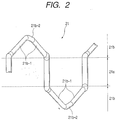
- Fig. 2 is a perspective view of an electric conductor on a stator in the alternator of the first embodiment of this invention.
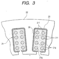
- Fig. 3 is a sectional view of the stator in the alternator of the first embodiment of this invention.
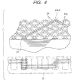
- Fig. 4 are views of the stator in the alternator of the first embodiment of this invention.
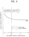
- Fig. 5 is a diagram showing the relation among the temperature of an electric conductor, the magnitude of the gaps between pieces of the electric conductor, and the degree of insulation.
- Fig. 6 is a diagrammatic view of a stator in an alternator for a vehicle according to a second embodiment of this invention.
- Fig. 7 is a perspective view of an electric conductor segment used in a winding on a stator in the alternator of the second embodiment of this invention.
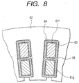
- Fig. 8 is a sectional view of the stator in the alternator of the second embodiment of this invention.
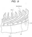
- Fig. 9 is a perspective view of the stator in the alternator of the second embodiment of this invention.
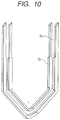
- Fig. 10 is a perspective view of electric conductor segments used in a winding on a stator in an alternator for a vehicle according to a third embodiment of this invention.
- Fig. 11 is a sectional view of the stator in the alternator of the third embodiment of this invention.
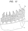
- Fig. 12 is a perspective view of the stator in the alternator of the third embodiment of this invention.
- an alternator 1 for an automotive vehicle includes a stator 2, a rotor 3, a housing 4, and a rectifier 5.
- the stator 2 serves as an armature.
- the rotor 3 generates a magnetic field.
- the housing 4 supports the stator 2 and the rotor 3.
- the housing 4 is also referred to as the frame 4.
- the rectifier 5 is directly connected to the stator 2.
- the rectifier 5 converts alternating current power into direct current power.
- the rotor 3 rotates together with a shaft 31.
- the rotor 3 includes a pair of Lundel-type pole cores 32, cooling fans 33, a field coil 34, and slip rings 35.
- the shaft 31 is connected to a pulley, being rotated and driven by an engine (not shown) mounted on the automotive vehicle for powering the same.
- the housing 4 has outlets 41 for cooling winds which extend in areas opposing electric-conductor bridge portions 21b of the stator 2.
- the housing 41 has end faces in an axial direction which are formed with inlets 42 for cooling winds.
- the stator 2 includes an electric conductor 21, an iron core 22, and an insulator 23.
- the electric conductor 21 forms a winding on the iron core 22.
- the insulator 23 provides electric insulation between the electric conductor 21 and the iron core 22.
- the stator 2 is supported by the housing 4.
- the iron core 22 is of the multiple-layer type in which thin steel plates are Iaminated.
- the iron core 22 has inner circumferential surfaces formed with a plurality of slots 24. Side surfaces of the slots 24 are approximately parallel to each other. The dimension of the open ends of the slots 24 is smaller than the distance between the side surfaces thereof.
- the electric conductor 21 has accommodated portions 21a and bridge portions 21b.
- the accommodated portions 21a are placed in the slots 24.
- the bridge portions 21b connect the accommodated portions 21a. Segments of the electric conductor 21 which extend from the slots 24 are approximately separated into a conductor group 21f located on outer radial sides of the slots 24 and a conductor group 21g located on inner radial sides of the slots 24.
- the conductor groups 21f and 21g compose the bridge portions 21b. Adjacent conductor pieces in the bridge portions 21b are spaced from each other by a predetermined gap or a predetermined clearance.
- Each of the bridge portions 21b has two ridge portions 21b-1, and a top portion 21b-2 connecting the ridge portions 21b-1 along an axial and radial direction.
- the ridge portions 21b-1 are inclined in a same circumferential direction in each of the outer radial side and the inner radial side.
- conductor pieces in the bridge portions 21b are thinner than the accommodated portions 21a. In other words, the conductor pieces in the bridge portions 21b are smaller in cross section than the accommodated portions 21a.
- the electric conductor 21 can be formed by drawing parts of a circular-cross-section wire coated with an insulating film, and thereby providing variations in the wire diameter.
- the insulator 23 has a shape such as shown in Fig. 3.
- the insulator 23 uses a high heatproof film made of material containing, for example, mica.
- the portions of the electric conductor which are accommodated in the slots 24 are subjected to an impregnation process to more firmly fix the positional relations among the iron core 22, the insulator 23, and the pieces of the electric conductor 21.
- the pieces of the electric conductor 21 in the slots 24 are surrounded by an impregnation agent 26.
- the impregnation agent 26 forms a part of an insulating layer covering the electric conductor 21 in the slots 24. Accordingly, the thickness of the insulating layers on the accommodated portions in the slots 24 is greater than the thickness of the insulating layers on the bridge portions by a value corresponding to the impregnation agent 26.
- the stator winding has three phases provided with phase ends 25. Regarding each of the three phases, a first end thereof is extended along an axial direction, and is electrically connected to an electrode 53 of a rectifying diode 53 in the rectifier 5. Second ends of the three phases are connected as a neutral point.
- the direction of the inclination of the ridge portions in the conductor group located in the outer radial side can be equal to the direction of the inclination of the ridge portions in the conductor group located in the inner radial side.
- the conductor group in the outer radial side and the conductor group in the inner radial side from overlapping and interfering with each other.
- pieces of the electric conductor in the bride portions 21b are thinner than the accommodated portions 21a of the electric conductor. Therefore, it is easy to provide predetermined gaps between adjacent pieces of the electric conductor for electric insulation.
- the envelope dimensions (the axial-direction dimension and the radial-direction dimension) as a whole of the bridge portions of the electric conductor can be equal to or smaller than those in a prior-art structure.
- the gap (the spacing) between the pieces of the electric conductor in the bridge portions is set to, for example, about 0.5 mm.
- Fig. 5 shows the relation among the temperature of the electric conductor, the magnitude of the gaps between the pieces of the electric conductor, and the degree of the insulation which is obtained by various experimental tests. It is shown in Fig. 5 that gaps of 0.5 mm or more suffice for insulation and cooling. On the other hand, gaps of less than 0.5 mm cause increased resistances to cooling winds through the regions between the pieces of the electric conductor, thus hardly providing an adequate cooling performance. In the case of gaps of less than 0.5 mm, the affections of a variation in the temperature of the electric conductor and a vibration caused by the engine make it difficult to provide sufficient insulation. Thus, it is preferable to set the gaps to about 0.5 mm.
- the insulating layer covering the electric conductor 21 is thin so that the heat radiation from the electric conductor 21 is improved.
- Pieces of the electric conductor 21 in the accommodated portions 21a are sufficiently electrically insulated from the iron core 22 of the stator 2 by the insulator 23.
- Pieces of the electric conductor 21 in the bridge portions 21b are prevented from interfering with each other.
- the pieces of the electric conductor 21 in the bridge portions 21b are spaced from each other, and are hence electrically insulated from each other.
- the insulating layer covering the electric conductor 21 is thin, the heat radiation from the surfaces of the bridge portions of the electric conductor 21 is remarkably improved. Thus, it is possible to effectively suppress a rise in the temperature of the electric conductor 21 in the stator 2.
- the heat deterioration of the insulating layers is suppressed. Since the pieces of the electric conductor 21 in the bridge portions are spaced from each other, it is possible to improve the heat resisting property (the allowable temperature) of the electric conductor 21 and the insulating performance.
- the insulating layers are made of the high heatproof material. Accordingly, the heat resisting property (the allowable temperature) of the stator 2 is remarkably improved.
- the cooling fans 33 are provided on the ends of the rotor 3 in the axial direction.
- the cooling fans 33 are of the built-in type or the inner type.
- the housing 4 has the outlets 41 which extend in the areas opposing the electric-conductor bridge portions 21b. Accordingly, cooling air flows from the central axis toward the outlets 41 of the housing 4 through the gaps between the electric-conductor bridge portions 21b along the radially outward directions. Since the pieces of the electric conductor 21 in the bridge portions 21b are spaced from each other, the surfaces of the pieces of the electric conductor 21 are surely exposed to the cooling winds. Thus, it is possible to improve the cooling performance.
- the cooling air enables a sound wave to be repetitively reflected and absorbed in the regions around the pieces of the electric conductor 21. Accordingly, noise sound is remarkably reduced.
- the tops of the electric-conductor bridge portions 21b have shapes extending along the directions of flows of the cooling air.
- the cooling fans 33 are in axial positional agreement with the tops of the electric-conductor bridge portions 21b. Accordingly, the tops of the electric-conductor bridge portions 21b serve as effective heat radiation fins. Thus, it is possible to further improve the cooling performance.
- the embodiment of this invention makes it possible to remarkably improve the cooling performance related to the electric conductor 21. Since the pieces of the electric conductor 21 in the bridge portions 21b are spaced from each other, resistances to the cooling winds can be greatly decreased. Thus, it is possible to miniaturize the cooling fans 33 or to decrease the diameter of the cooling fans 33.
- the small-size fans 33 generate reduced fan noise.
- the small-size fans 33 are subjected to decreased centrifugal forces.
- the small-size fans 33 can be made of a thin and inexpensive member.
- the outside diameter of the electric-conductor bridge portions 21b can be decreased. Thus, it is possible to reduce the outside diameter of the frame (the housing) 4 which supports the stator 2 and the rotor 3. Accordingly, the miniaturization of the alternator 1 for the vehicle can be implemented.
- Figs. 6 to 9 show a stator 6 in an alternator for an automotive vehicle according to a second embodiment of this invention.
- the stator 6 includes electric conductor segments 61, an iron core 62, and an insulator 63.
- the electric conductor segments 61 compose a winding on the iron core 62.
- the insulator 63 provides electric insulation between the electric conductor segments 61 and the iron core 62.
- the winding is composed of the electric conductor segments 61 which are electrically connected.
- the winding includes turn portions 61d and connected portions 61e.
- the turn portions 61d are located on one side of the iron core 62 in an axial direction.
- the connected portions 61e are located on the other side of the iron core 62 in the axial direction.
- the electric conductor segments 61 have accommodated portions 61a and bridge portions 61b.
- the accommodated portions 61a are placed in slots 64 in the iron core 62.
- the bridge portions 61b connect the accommodated portions 61a.
- Adjacent bridge portions 61b are spaced from each other by a predetermined gap or a predetermined clearance which can provide electric insulation.
- the bridge portions 61b have ridge portions 61b-1 and top portions 61b-2.
- the ridge portions 61b-1 are inclined in a same circumferential direction in outer layers and inner layers.
- the top portions 61b-2 connect the ridge portions 61b-1 in an axial and radial direction.
- the top portions 61b-2 form the turn portions 61d and the connected portions 61e.
- each electric conductor segment 61 has stepped portions 61c.
- the cross-sectional area of each bridge portion 61b is smaller than that of each accommodated portion 61a.
- Each of the electric conductor segments 61 is made of a bare metal member.
- Each of the electric conductor segments 61 may be made of a metal member coated with an insulating film.
- the electric conductor segments 61 are formed by, for example, a pressing process. Thus, it is possible to reduce a material cost and a processing cost.
- the insulator 63 has an approximately S shape in order to provide insulation between the electric conductor segments 61 and the iron core 62, and insulation between the electric conductor segments 61 in each of the slots 64 in the iron core 62.
- the insulator 63 uses a high heatproof film made of material containing, for example, mica.
- the portions of the electric conductor which are accommodated in the slots 64 are subjected to an impregnation process to more firmly fix the positional relations among the iron core 62, the insulator 63, and the electric conductor segments 61.
- the electric conductor segments 61 in the slots 64 are surrounded by an impregnation agent 66.
- the impregnation agent 66 forms a part of an insulating layer covering each of the electric conductor segments 61 in the slots 64. Accordingly, the thickness of the insulating layers on the accommodated portions 61a in the slots 64 is greater than the thickness of the insulating layers on the bridge portions 61b by a value corresponding to the impregnation agent 66.
- the winding on the stator 6 is formed as follows.
- U-shaped electrically-conductive segments 61 are prepared which have approximately equal shapes. As shown in Fig. 7, each of the U-shaped segments 61 has an outer-layer-side conductor portion 61f, an inner-layer-side conductor portion 61g, and a conductor turn portion 61d.
- the U-shaped segments 61 are arranged with respect to the iron core 62 so that the turn portions 61d will align with each other on one side of the iron core 62 in the axial direction.
- the U-shaped segments 61 are inserted into the slots 64 in a manner such that the outer-layer-side conductor portions 61f are located in outer areas of the slots 64 while the inner-layer-side conductor portions 61g are located in inner areas of the slots 64.
- each of the U-shaped segments 61 is formed by bending a copper plate and pressing it into an approximately U shape. The U-shaped segments 61 are pressed into the slots 64 so that the outer radial side surfaces and the inner radial side surfaces of the accommodated portions 61a will engage the side surfaces of the slots 64 via the insulators 63.
- the ends of the outer-layer-side conductor portions 61f remote from the turn portions 61d are bent toward a first circumferential direction while the ends of the inner-layer-side conductor portions 61g are bent toward a second circumferential direction opposite to the first circumferential direction.
- the ends of the U-shaped segments 61 are connected so that the electric conductor segments 61 in each common phase will be electrically connected together.
- the direction of the inclination of the ridge portions located in the inner layer side can be equal to the direction of the inclination of the ridge portions located in the outer layer side.
- the electric-conductor bridge portions have the stepped portions 61c.
- sufficient gaps can be provided and the ridge portions of the electric conductor can be prevented from interfering each other even in regions where the inner-layer-side and outer-layer-side ridge portions are inclined and are adjacent to each other as crosses while the envelope dimensions (the axial-direction dimension and the radial-direction dimension) of the bridge portions of the electric conductor are prevented from becoming greater than those in a prior-art structure.
- the windings on the stator 6 do not use any insulating film covering the electric conductor which would deteriorate the heat radiation from the electric conductor.
- the electric conductor segments 61 are made of the bare metal members, the insulator 53 provides sufficient electric insulation with respect to the accommodated portions 61a.
- the bridge portions 61b are spaced from each other so that they can be prevented from interfering with each other, and that sufficient electric insulation can be provided therebetween.
- the electric conductor uses the approximately U-shaped segments.
- the bridge portions can be made separate from each other without using any special jig. Thus, it is possible to remarkably reduce a manufacture cost.
- Figs. 10 to 12 show a third embodiment of this invention. While two electric conductor segments are inserted into one slot in the stator in the second embodiment of this invention, four electric conductor segments are inserted into one slot in a stator in the third embodiment of this invention.
- the third embodiment of this invention is similar in basic structure to the second embodiment thereof.
- electric conductor segments 7a and 7b approximately correspond to possible halves of the electric conductor segment 61 in Fig. 7, respectively.
- the electric conductor segments 7a and 7b are electrically insulated from each other as follows.
- a U-shaped member is halved into electric conductor segments 7a and 7b.
- the electric conductor segment 7a is located outward of the electric conductor segment 7b.
- the outer-side electric conductor segment 7a has stepped portions similar in shape to the stepped portions in the electric conductor segment 61 of Fig. 7.
- the inner-side electric conductor segment 7b is provided with stepped portions at two sides of a bridge portion.
- the stepped portions in the electric conductor segments 7b are designed to provide sufficient insulating gaps in regions where the bridge portions are inclined and are adjacent to each other as crosses after the electric conductor segments 7a and 7b are inserted into slots in the stator.
- two approximately S-shaped insulators 73 are arranged in each slot in the stator.
- the two insulators 73 provide insulation in the slot.
- the portions of the electric conductor which are accommodated in the slots are subjected to an impregnation process to more firmly fix the positional relations among an iron core 72, the insulators 73, and the electric conductor segments 7a and 7b.
- the electric conductor segments 7a and 7b in the slots are surrounded by an impregnation agent 76.
- insulating material may be applied to the bridge portions of the electric conductor to form insulating films covering the bare metal wires in the bridge portions.
Landscapes
- Engineering & Computer Science (AREA)
- Power Engineering (AREA)
- Motor Or Generator Cooling System (AREA)
- Windings For Motors And Generators (AREA)
Abstract
Description
Claims (6)
- An alternator for a vehicle, comprising:wherein the stator includes a stator iron core and a stator winding, the stator winding being provided on the stator iron core and including a plurality of segment conductors, the stator winding forming two coil ends which project from two end surfaces of the stator iron core in axial directions respectively,a rotor;a stator located so as to confront a radial-direction outer side of the rotor;a fan located on the rotor and extending radially inward of the stator; anda frame supporting the rotor and the stator,
wherein a plurality of joint portions including connections between ends of the segment conductors are arranged in a multiple-ring shape in one of the two coil ends, the joint portions being radially spaced from each other in radial directions, the joint portions being spaced at equal intervals in a circumferential direction along one ring of the multiple-ring shape, and
wherein the frame has a plurality of openings in a radial-direction outer side of said one of the two coil ends. - An alternator according to claim 1, wherein the rotor includes a Lundel-type pole core having a plurality of claw-like magnetic poles, and the fan is provided on an axial-direction end surface of the pole core.
- An alternator according to claim 1, wherein circumferential-direction intervals between the joint portions are greater than radial-direction intervals between the joint portions.
- An alternator according to claim 1, wherein each of the segment conductors has a U shape with a turn portion, and the turn portion is located in the other of the two coil ends.
- An alternator for a vehicle, comprising:wherein the stator winding includes a plurality of U-shaped segment conductors and forms two coil ends which project from two end surfaces of the stator iron core in axial directions respectively, the segment conductors including U-shaped turn portions respectively;a rotor including a Lundel-type pole core having a plurality of claw-like magnetic poles;a cooling fan provided on an axial-direction end surface of the pole core for rotation together with the pole core;a stator including a stator iron core and a stator winding, the stator iron core being located so as to confront the rotor, the stator winding being provided on the stator iron core; anda frame supporting the rotor and the stator;
wherein the U-shaped turn portions are located in one of the two coil ends, and ends of the segment conductors are located in the other of the two coil ends;
wherein the ends of the segment conductors are connected at joint portions which are arranged in a multiple-ring shape;
wherein joint portions in a first ring of the multiple-ring shape are spaced at equal intervals along a common circumference;
wherein joint portions in a second ring of the multiple-ring shape are radially spaced from each other; and
wherein the frame has a plurality of openings in a radial-direction outer side of at least one of the two coil ends. - An alternator for a vehicle, comprising:wherein the stator winding includes a plurality of U-shaped segment conductors and forms two coil ends which project from two end surfaces of the stator iron core in axial directions, respectively, the U-shaped segment conductors including U-shaped turn portions, respectively,a rotor including a Lundel-type pole core having a plurality of claw-like magnetic poles;a cooling fan provided on an axial-direction end surface of the pole core for rotation together with the pole core;a stator including a stator iron core and a stator winding, the stator core being located so as to confront the rotor, the stator winding being provided on the stator iron core; anda frame supporting the rotor and the stator,
wherein the U-shaped turn portions are located in one of the two coil ends, and ends of the segment conductors are located in the other of the two coil ends,
wherein the ends of the segment conductors are connected at joint portions which are arranged in a multiple-ring shape,
wherein joint portions in a first ring of the multiple-ring shape are spaced at equal intervals along a common circumference,
wherein joint portions in a second ring of the multiple-ring shape are radially spaced from each other, the second ring extending radially inward of the first ring, and
wherein the frame has a plurality of openings in a radial-direction outer side of at least one of the two coil ends.
Applications Claiming Priority (7)
| Application Number | Priority Date | Filing Date | Title |
|---|---|---|---|
| WOPCT/JP97/01778 | 1997-05-26 | ||
| PCT/JP1997/001778 WO1998054822A1 (en) | 1997-05-26 | 1997-05-26 | Ac generator for vehicle |
| WOPCT/JP97/03374 | 1997-09-22 | ||
| PCT/JP1997/003374 WO1998054823A1 (en) | 1997-05-26 | 1997-09-22 | Ac generator for vehicle |
| JP27975197 | 1997-09-26 | ||
| JP27975197 | 1997-09-26 | ||
| EP98109128A EP0881747B2 (en) | 1997-05-26 | 1998-05-19 | Alternator for vehicle |
Related Parent Applications (2)
| Application Number | Title | Priority Date | Filing Date |
|---|---|---|---|
| EP98109128A Division EP0881747B2 (en) | 1997-05-26 | 1998-05-19 | Alternator for vehicle |
| EP98109128.3 Division | 1998-05-19 |
Publications (2)
| Publication Number | Publication Date |
|---|---|
| EP1237254A1 true EP1237254A1 (en) | 2002-09-04 |
| EP1237254B1 EP1237254B1 (en) | 2008-06-04 |
Family
ID=37308895
Family Applications (3)
| Application Number | Title | Priority Date | Filing Date |
|---|---|---|---|
| EP98109128A Expired - Lifetime EP0881747B2 (en) | 1997-05-26 | 1998-05-19 | Alternator for vehicle |
| EP02008398A Expired - Lifetime EP1237254B1 (en) | 1997-05-26 | 1998-05-19 | Alternator for vehicle |
| EP02008399A Expired - Lifetime EP1227567B1 (en) | 1997-05-26 | 1998-05-19 | Alternator for vehicles |
Family Applications Before (1)
| Application Number | Title | Priority Date | Filing Date |
|---|---|---|---|
| EP98109128A Expired - Lifetime EP0881747B2 (en) | 1997-05-26 | 1998-05-19 | Alternator for vehicle |
Family Applications After (1)
| Application Number | Title | Priority Date | Filing Date |
|---|---|---|---|
| EP02008399A Expired - Lifetime EP1227567B1 (en) | 1997-05-26 | 1998-05-19 | Alternator for vehicles |
Country Status (4)
| Country | Link |
|---|---|
| US (3) | US5936326A (en) |
| EP (3) | EP0881747B2 (en) |
| JP (1) | JP3744258B2 (en) |
| DE (1) | DE69811564T3 (en) |
Cited By (5)
| Publication number | Priority date | Publication date | Assignee | Title |
|---|---|---|---|---|
| WO2005004309A1 (en) * | 2003-07-01 | 2005-01-13 | Siemens Aktiengesellschaft | Electric motor for a drive unit of a vehicle, especially railroad drive units, and drive unit comprising such an electric motor |
| WO2007125786A1 (en) * | 2006-04-24 | 2007-11-08 | Toyota Jidosha Kabushiki Kaisha | Stator of rotating electric machine, and component for use in stator |
| CN107786020A (en) * | 2016-08-24 | 2018-03-09 | 株式会社电装 | The stator of electric rotating machine |
| DE102018219817A1 (en) * | 2018-11-19 | 2020-05-20 | Mahle International Gmbh | Electrical machine, in particular for a vehicle |
| DE102018219816A1 (en) * | 2018-11-19 | 2020-05-20 | Mahle International Gmbh | Electrical machine, in particular for a vehicle |
Families Citing this family (113)
| Publication number | Priority date | Publication date | Assignee | Title |
|---|---|---|---|---|
| DE69811564T3 (en) | 1997-05-26 | 2009-04-30 | Denso Corp., Kariya-shi | Alternator for motor vehicles |
| DE19736645C2 (en) * | 1997-08-22 | 1999-12-02 | Gruendl & Hoffmann | Wanderfeldmaschine |
| JP3769990B2 (en) * | 1999-08-06 | 2006-04-26 | 株式会社デンソー | Conductor segment bonding type rotating electrical machine and method for manufacturing the same |
| JP3899685B2 (en) * | 1998-06-26 | 2007-03-28 | 株式会社デンソー | Stator for vehicle alternator and manufacturing method thereof |
| JP3427748B2 (en) | 1998-10-09 | 2003-07-22 | 株式会社デンソー | AC generator for vehicles |
| JP3284981B2 (en) * | 1998-11-02 | 2002-05-27 | 株式会社デンソー | Method for manufacturing vehicle alternator and stator thereof |
| JP3250533B2 (en) * | 1998-11-25 | 2002-01-28 | 株式会社デンソー | Stator for vehicle alternator and method of manufacturing the same |
| JP3199068B2 (en) * | 1999-03-31 | 2001-08-13 | 株式会社デンソー | Stator manufacturing equipment |
| JP4029519B2 (en) * | 1999-04-12 | 2008-01-09 | 株式会社デンソー | Vehicle alternator stator |
| JP2001037131A (en) * | 1999-07-15 | 2001-02-09 | Mitsubishi Electric Corp | AC generator for vehicles |
| USD448343S1 (en) | 1999-10-06 | 2001-09-25 | Mitsubishi Denki Kabushiki Kaisha | Stator of AC generator for vehicles |
| USD447115S1 (en) | 1999-12-14 | 2001-08-28 | Mitsubishi Denki Kabushiki Kaisha | Stator of AC generator for vehicles |
| USD447731S1 (en) | 1999-12-14 | 2001-09-11 | Mitsubishi Denki Kabushiki Kaisha | Stator of AC generator for vehicles |
| JP3383251B2 (en) * | 1999-12-27 | 2003-03-04 | 三菱電機株式会社 | Vehicle alternator stator |
| JP3347115B2 (en) * | 1999-12-20 | 2002-11-20 | 三菱電機株式会社 | AC generator |
| EP1109296B1 (en) * | 1999-12-14 | 2003-06-11 | Mitsubishi Denki Kabushiki Kaisha | Alternator |
| USD447114S1 (en) | 1999-12-14 | 2001-08-28 | Mitsubishi Denki Kabushiki Kaisha | Stator of AC generator for vehicles |
| USD448004S1 (en) | 1999-12-14 | 2001-09-18 | Mitsubishi Denki Kabushiki Kaisha | Stator of AC generator for vehicles |
| JP3347116B2 (en) * | 2000-01-12 | 2002-11-20 | 三菱電機株式会社 | Alternator |
| JP2001211588A (en) * | 2000-01-27 | 2001-08-03 | Mitsubishi Electric Corp | Alternator |
| JP3448253B2 (en) * | 2000-01-31 | 2003-09-22 | 三菱電機株式会社 | AC generator |
| JP4462392B2 (en) * | 2000-02-23 | 2010-05-12 | 三菱電機株式会社 | Method of manufacturing an alternator stator |
| JP4318827B2 (en) * | 2000-02-24 | 2009-08-26 | 三菱電機株式会社 | AC generator |
| DE10008803A1 (en) * | 2000-02-25 | 2001-09-13 | Siemens Ag | Electric rotary machine |
| JP4014071B2 (en) | 2000-03-13 | 2007-11-28 | 三菱電機株式会社 | AC generator, winding assembly thereof, and method of manufacturing winding assembly |
| JP3783832B2 (en) * | 2000-03-30 | 2006-06-07 | 三菱電機株式会社 | AC generator for vehicles |
| JP2001286082A (en) * | 2000-04-03 | 2001-10-12 | Mitsubishi Electric Corp | Alternator stator |
| US6943477B1 (en) | 2000-04-27 | 2005-09-13 | Denso Corporation | Stator of rotary electric machine and method for making the same |
| DE10119776A1 (en) * | 2000-04-27 | 2001-11-08 | Denso Corp | Stator of an induction machine and method for its production |
| JP4461590B2 (en) * | 2000-08-25 | 2010-05-12 | 株式会社デンソー | Vehicle alternator |
| JP3476438B2 (en) * | 2001-01-19 | 2003-12-10 | 三菱電機株式会社 | AC generator for vehicles |
| JP3633494B2 (en) * | 2001-02-20 | 2005-03-30 | 株式会社デンソー | Rotating electric machine |
| JP3566665B2 (en) * | 2001-04-06 | 2004-09-15 | 三菱電機株式会社 | Rotating machine stator |
| JP3593059B2 (en) * | 2001-05-28 | 2004-11-24 | 三菱電機株式会社 | AC generator for vehicles |
| US7064466B2 (en) * | 2001-11-27 | 2006-06-20 | Denso Corporation | Brushless rotary electric machine having tandem rotary cores |
| US7170211B2 (en) * | 2002-01-24 | 2007-01-30 | Visteon Global Technologies, Inc. | Stator winding having transitions |
| US6787961B2 (en) | 2002-12-19 | 2004-09-07 | Visteon Global Technologies, Inc. | Automotive alternator stator assembly with varying end loop height between layers |
| US6930426B2 (en) * | 2003-11-26 | 2005-08-16 | Visteon Global Technologies, Inc. | Alternator stator having a multiple filar construction to improve convective cooling |
| US6882077B2 (en) * | 2002-12-19 | 2005-04-19 | Visteon Global Technologies, Inc. | Stator winding having cascaded end loops |
| US6750581B2 (en) * | 2002-01-24 | 2004-06-15 | Visteon Global Technologies, Inc. | Automotive alternator stator assembly with rectangular continuous wire |
| GB2389717B (en) * | 2002-01-24 | 2004-07-28 | Visteon Global Tech Inc | Automotive alternator stator assembly and winding method |
| US7129612B2 (en) * | 2002-01-24 | 2006-10-31 | Visteon Global Technologies, Inc. | Stator assembly with cascaded winding and method of making same |
| KR100450897B1 (en) * | 2002-02-27 | 2004-10-01 | 미쓰비시덴키 가부시키가이샤 | Stator of dynamo-electric machine |
| JP4019951B2 (en) * | 2002-03-01 | 2007-12-12 | 株式会社デンソー | Manufacturing method of winding of rotating electrical machine and processing method of winding recess |
| US20030214190A1 (en) * | 2002-05-15 | 2003-11-20 | Delco Remy America | Connection device for hairpin wound electric machines |
| DE10321956B4 (en) | 2002-05-15 | 2013-09-12 | Remy Inc. | Windings of rectangular copper hairpins in multiple sets for electrical machines |
| US6979926B2 (en) * | 2002-06-12 | 2005-12-27 | Denso Corporation | Sequentially joined-segment coil for rotary electrical machine |
| US20040000820A1 (en) * | 2002-06-13 | 2004-01-01 | Cromas Joseph Charles | Automotive generator |
| US20050023909A1 (en) * | 2002-06-13 | 2005-02-03 | Cromas Joseph Charles | Automotive generator |
| JP3783660B2 (en) * | 2002-06-25 | 2006-06-07 | 株式会社デンソー | Segment sequential joining stator coil of rotating electrical machine |
| JP2004048890A (en) * | 2002-07-11 | 2004-02-12 | Denso Corp | Rotary electric machine |
| JP3791471B2 (en) | 2002-07-12 | 2006-06-28 | 株式会社デンソー | Segment sequential stator coil type rotating electrical machine |
| JP3815674B2 (en) | 2002-07-15 | 2006-08-30 | 株式会社デンソー | Segment sequential stator coil type rotating electrical machine |
| US6825586B2 (en) * | 2002-10-29 | 2004-11-30 | Remy, Inc. | One piece stator lead and terminal insulator |
| JP2004229460A (en) * | 2003-01-27 | 2004-08-12 | Mitsubishi Electric Corp | Rotating electric machine stator |
| US6949857B2 (en) * | 2003-03-14 | 2005-09-27 | Visteon Global Technologies, Inc. | Stator of a rotary electric machine having stacked core teeth |
| JP2004320906A (en) * | 2003-04-17 | 2004-11-11 | Denso Corp | AC generator for vehicles |
| US6922001B2 (en) * | 2003-12-02 | 2005-07-26 | Visteon Global Technologies, Inc. | Process for assembling an alternator stator with clips that allows radial insertion of square wire with small slot openings |
| CN100479296C (en) * | 2004-05-28 | 2009-04-15 | 三菱电机株式会社 | AC generator for vehicle |
| US7081697B2 (en) * | 2004-06-16 | 2006-07-25 | Visteon Global Technologies, Inc. | Dynamoelectric machine stator core with mini caps |
| US7386931B2 (en) * | 2004-07-21 | 2008-06-17 | Visteon Global Technologies, Inc. | Method of forming cascaded stator winding |
| US7269888B2 (en) | 2004-08-10 | 2007-09-18 | Visteon Global Technologies, Inc. | Method of making cascaded multilayer stator winding with interleaved transitions |
| JP4424163B2 (en) * | 2004-11-10 | 2010-03-03 | 株式会社デンソー | Vehicle alternator |
| US20060152100A1 (en) * | 2005-01-07 | 2006-07-13 | Visteon Global Technologies, Inc. | Vehicle alternator having reduced windings |
| DE502005000248D1 (en) * | 2005-03-17 | 2007-02-01 | Zahnradfabrik Friedrichshafen | Stator for an electric machine |
| JP4501762B2 (en) * | 2005-04-18 | 2010-07-14 | 株式会社デンソー | Vehicle alternator |
| JP2007020302A (en) * | 2005-07-07 | 2007-01-25 | Denso Corp | Dynamo electric machine for vehicle |
| JP4640008B2 (en) * | 2005-07-15 | 2011-03-02 | 株式会社デンソー | Rotating electric machine for vehicles |
| JP4453670B2 (en) * | 2006-02-24 | 2010-04-21 | 株式会社デンソー | Vehicle alternator stator |
| JP4450235B2 (en) * | 2006-05-25 | 2010-04-14 | 株式会社デンソー | AC generator |
| JP4692439B2 (en) * | 2006-08-22 | 2011-06-01 | 株式会社デンソー | AC generator for vehicles |
| JP4910572B2 (en) * | 2006-08-30 | 2012-04-04 | 株式会社デンソー | Rotating electric machine for vehicles |
| JP4483845B2 (en) * | 2006-09-12 | 2010-06-16 | 株式会社デンソー | Vehicle alternator |
| FR2908941B1 (en) * | 2006-11-22 | 2014-03-14 | Valeo Equip Electr Moteur | METHOD FOR PRODUCING A FAN DEVICE FOR A ROTATING ELECTRIC MACHINE AND A FAN DEVICE FOR CARRYING OUT SAID METHOD |
| JP4475470B2 (en) * | 2007-04-05 | 2010-06-09 | 三菱電機株式会社 | Insulation structure of coil part of rotating electrical machine |
| FR2918815A1 (en) * | 2007-07-11 | 2009-01-16 | Valeo Equip Electr Moteur | POLYPHASE STATOR FOR INTERNAL VENTILATION ROTATING ELECTRIC MACHINE AND ROTATING ELECTRIC MACHINE COMPRISING SUCH A STATOR. |
| RU2483413C2 (en) * | 2007-08-03 | 2013-05-27 | Альстом Текнолоджи Лтд | Electric machine, in particular, three-phase asynchronous hydrogenerator |
| JP4873261B2 (en) * | 2007-11-20 | 2012-02-08 | 株式会社デンソー | Method for manufacturing coil assembly of rotating electrical machine |
| JP4396761B2 (en) | 2007-11-26 | 2010-01-13 | 株式会社デンソー | Rotating electric machine stator and rotating electric machine |
| EP2063515A3 (en) * | 2007-11-26 | 2010-10-27 | Denso Corporation | Stator for rotary electric machine, and rotary electric machine using the stator |
| JP4479788B2 (en) | 2007-12-20 | 2010-06-09 | 株式会社デンソー | Coil forming method and coil forming die |
| US8258668B2 (en) * | 2007-12-27 | 2012-09-04 | Aisin Aw Co., Ltd. | Stator and rotating electric machine employing the same |
| JP5167939B2 (en) * | 2008-05-12 | 2013-03-21 | 株式会社デンソー | Method for manufacturing coil assembly of rotating electrical machine |
| JP5332347B2 (en) * | 2008-06-30 | 2013-11-06 | 株式会社デンソー | Coil wire rod for coil assembly of rotating electrical machine |
| JP5260399B2 (en) * | 2009-04-24 | 2013-08-14 | 日立オートモティブシステムズ株式会社 | Rotating electric machine for driving vehicle and vehicle using the same |
| US8456053B2 (en) * | 2009-08-28 | 2013-06-04 | GM Global Technology Operations LLC | Insulation assembly for a stator core |
| JP5134064B2 (en) * | 2010-11-18 | 2013-01-30 | トヨタ自動車株式会社 | Rotating electric machine |
| US9130430B2 (en) * | 2011-03-18 | 2015-09-08 | Remy Technologies Llc | Electric machine with fully enclosed in-slot conductors |
| JP5565381B2 (en) * | 2011-06-17 | 2014-08-06 | 株式会社デンソー | Rotating electric machine stator |
| DE102012108943B4 (en) | 2011-09-24 | 2026-01-22 | Denso Corporation | Rotating electric machine |
| JP5502913B2 (en) * | 2012-01-23 | 2014-05-28 | 三菱電機株式会社 | Rotating electric machine |
| US9502931B2 (en) | 2012-03-23 | 2016-11-22 | Asmo Co., Ltd. | Brushless motor |
| JP5724984B2 (en) * | 2012-10-19 | 2015-05-27 | トヨタ自動車株式会社 | Rotating electric machine stator |
| US20140111055A1 (en) * | 2012-10-23 | 2014-04-24 | Remy Technologies, L.L.C. | Conductor with divot for improved form factor |
| JP6094149B2 (en) * | 2012-10-31 | 2017-03-15 | アイシン精機株式会社 | Wave winding of three-phase rotating electric machine |
| DE102012223711A1 (en) * | 2012-12-19 | 2014-06-26 | Robert Bosch Gmbh | Electric machine |
| DE102012223705A1 (en) * | 2012-12-19 | 2014-06-26 | Robert Bosch Gmbh | Electric machine |
| JP5939446B2 (en) | 2013-03-29 | 2016-06-22 | 株式会社デンソー | Stator, rotating electric machine including the stator, and method for manufacturing the stator |
| JP5720715B2 (en) | 2013-03-29 | 2015-05-20 | 株式会社デンソー | Rotating electric machine |
| JP5907128B2 (en) | 2013-08-21 | 2016-04-20 | 株式会社デンソー | Rotating electric machine stator |
| US10396614B2 (en) | 2013-09-18 | 2019-08-27 | Mitsubishi Electric Corporation | Rotating electrical machine stator |
| JP5748878B2 (en) * | 2014-03-13 | 2015-07-15 | 三菱電機株式会社 | Rotating electric machine |
| FR3019947B1 (en) * | 2014-04-10 | 2017-12-08 | Moteurs Leroy-Somer | STATOR OF ROTATING ELECTRIC MACHINE. |
| FR3019948B1 (en) | 2014-04-10 | 2017-12-22 | Moteurs Leroy-Somer | ROTOR OF ELECTRIC ROTATING MACHINE. |
| FR3020521B1 (en) * | 2014-04-29 | 2016-06-03 | Nicolas Langlard | ROTATING ELECTRIC MACHINE STATOR WITH OPTIMIZED WINDING |
| JP6405775B2 (en) | 2014-08-07 | 2018-10-17 | 株式会社デンソー | Double stator rotary electric machine |
| JP6222032B2 (en) | 2014-10-14 | 2017-11-01 | 株式会社デンソー | Rotating electric machine |
| JP6591198B2 (en) * | 2015-05-22 | 2019-10-16 | 日立オートモティブシステムズ株式会社 | Rotating electric machine stator |
| JP6601038B2 (en) | 2015-07-28 | 2019-11-06 | 株式会社デンソー | Manufacturing method of rotating electrical machine |
| JP6658559B2 (en) | 2017-01-13 | 2020-03-04 | 株式会社デンソー | Rotating electric machine stator |
| JP6642494B2 (en) * | 2017-03-10 | 2020-02-05 | トヨタ自動車株式会社 | Manufacturing equipment for stators of rotating electric machines |
| CN113632343B (en) * | 2019-03-29 | 2024-08-16 | 日本电产株式会社 | Stator, method for manufacturing stator, and motor |
| AU2021317637B2 (en) | 2020-07-31 | 2025-02-20 | Copenhagen Atomics A/S | A canned rotodynamic flow machine for a molten salt nuclear reactor and an active magnetic bearing for use in a flow machine for a molten salt nuclear reactor |
Citations (5)
| Publication number | Priority date | Publication date | Assignee | Title |
|---|---|---|---|---|
| US1826295A (en) * | 1928-06-14 | 1931-10-06 | Vincent G Apple | Dynamo electric machine element |
| JPS57129141A (en) * | 1981-02-03 | 1982-08-11 | Kazuo Sano | Single layer half-wound coil |
| JPS63274335A (en) * | 1987-04-30 | 1988-11-11 | Nippon Denso Co Ltd | Armature coil |
| JPH0327748A (en) * | 1989-06-20 | 1991-02-06 | Nippondenso Co Ltd | Ac generator for vehicle |
| EP0740400A1 (en) * | 1995-04-26 | 1996-10-30 | Valeo Equipements Electriques Moteur | Car altenator with external baffle to prevent recirculation of the cooling air |
Family Cites Families (32)
| Publication number | Priority date | Publication date | Assignee | Title |
|---|---|---|---|---|
| GB191123548A (en) * | 1911-10-25 | 1912-10-10 | P R Jackson And Company Ltd | Improvements in the Windings of Electric Generators and other Electrical Machines. |
| DE270642C (en) * | 1911-12-23 | |||
| CH149526A (en) * | 1930-09-09 | 1931-09-15 | Oerlikon Maschf | Grid winding for AC machines. |
| US2407935A (en) * | 1944-05-25 | 1946-09-17 | Chrysler Corp | Electrical machine |
| US2928963A (en) † | 1956-06-06 | 1960-03-15 | Gen Motors Corp | Dynamoelectric machine |
| GB863073A (en) * | 1957-03-12 | 1961-03-15 | Westinghouse Electric Corp | Improvements in or relating to dynamo electric machines |
| CH546501A (en) * | 1972-06-20 | 1974-02-28 | Bbc Brown Boveri & Cie | METHOD OF MANUFACTURING BARRIERS FOR THE STATOR WINDING OF A ROTATING ELECTRIC HIGH VOLTAGE MACHINE. |
| JPS55141947A (en) * | 1979-04-24 | 1980-11-06 | Toshiba Corp | Insulation of channel of rotary electric machine |
| JPS57132743A (en) * | 1981-02-09 | 1982-08-17 | Nippon Denso Co Ltd | Ac generator for vehicle |
| JPS59127546A (en) * | 1983-01-10 | 1984-07-23 | Mitsubishi Electric Corp | Armature coil for rotary electric machine |
| US4425519A (en) * | 1983-04-19 | 1984-01-10 | General Electric Company | Crack resistant armor termination for pole face winding bars |
| JPS61221561A (en) * | 1985-03-27 | 1986-10-01 | Nippon Denso Co Ltd | Flat rotary electric machine |
| JPH0744797B2 (en) * | 1986-05-20 | 1995-05-15 | 日本電装株式会社 | Armature coil |
| US4907541A (en) | 1986-06-16 | 1990-03-13 | Thompson Paul L | Pet restraint |
| US4908541A (en) * | 1986-08-28 | 1990-03-13 | Mitsuba Electric Mfg., Co., Ltd. | Air-cooled layered coil vehicle AC generator stator |
| JPS6359744A (en) * | 1986-08-28 | 1988-03-15 | Mitsuba Electric Mfg Co Ltd | Stator coil structure of generator for vehicle |
| JPS645340A (en) * | 1987-06-25 | 1989-01-10 | Nippon Denso Co | Rotating electric machine |
| JPS6427406A (en) * | 1987-07-21 | 1989-01-30 | Minoru Sangyo | Aerator for hastening germination |
| JPH03270657A (en) † | 1990-03-16 | 1991-12-02 | Nippondenso Co Ltd | Stator of ac generator and manufacture of the stator |
| JP2893859B2 (en) * | 1990-05-15 | 1999-05-24 | 富士通株式会社 | Evaluation method of silicon crystal |
| DE4129411C2 (en) * | 1990-09-28 | 1995-10-12 | Mitsubishi Electric Corp | Vehicle alternator |
| DE9017835U1 (en) * | 1990-10-04 | 1992-03-12 | Robert Bosch Gmbh, 7000 Stuttgart | Stands for electrical machines |
| JPH05308737A (en) * | 1992-04-28 | 1993-11-19 | Mitsubishi Electric Corp | Armature, winding conductor and manufacture of conductor |
| JPH05308736A (en) * | 1992-04-28 | 1993-11-19 | Mitsubishi Electric Corp | Armature and its winding conductor |
| JP2548882B2 (en) * | 1993-05-07 | 1996-10-30 | 日本電装株式会社 | Vehicle alternator |
| JP3419080B2 (en) * | 1993-07-26 | 2003-06-23 | 株式会社デンソー | Rotating electric machine |
| JP2829234B2 (en) * | 1993-12-28 | 1998-11-25 | 三菱電機株式会社 | AC generator for vehicles |
| JPH07222415A (en) * | 1994-02-02 | 1995-08-18 | Mitsubishi Electric Corp | Vehicle alternator |
| US5552651A (en) * | 1995-07-03 | 1996-09-03 | General Motors Corporation | Alternating current generator |
| JP3027748U (en) | 1996-02-08 | 1996-08-13 | 株式会社トミー | Binding machine |
| DE69811564T3 (en) * | 1997-05-26 | 2009-04-30 | Denso Corp., Kariya-shi | Alternator for motor vehicles |
| JP3027748B1 (en) | 1999-01-22 | 2000-04-04 | 日本フネン株式会社 | Flash Door Manufacturing Method |
-
1998
- 1998-05-19 DE DE69811564T patent/DE69811564T3/en not_active Expired - Lifetime
- 1998-05-19 EP EP98109128A patent/EP0881747B2/en not_active Expired - Lifetime
- 1998-05-19 EP EP02008398A patent/EP1237254B1/en not_active Expired - Lifetime
- 1998-05-19 EP EP02008399A patent/EP1227567B1/en not_active Expired - Lifetime
- 1998-05-26 US US09/084,101 patent/US5936326A/en not_active Expired - Lifetime
-
1999
- 1999-04-08 US US09/288,327 patent/US6051906A/en not_active Expired - Lifetime
- 1999-05-20 JP JP13995099A patent/JP3744258B2/en not_active Expired - Lifetime
-
2000
- 2000-03-06 US US09/515,241 patent/US6181045B1/en not_active Expired - Lifetime
Patent Citations (5)
| Publication number | Priority date | Publication date | Assignee | Title |
|---|---|---|---|---|
| US1826295A (en) * | 1928-06-14 | 1931-10-06 | Vincent G Apple | Dynamo electric machine element |
| JPS57129141A (en) * | 1981-02-03 | 1982-08-11 | Kazuo Sano | Single layer half-wound coil |
| JPS63274335A (en) * | 1987-04-30 | 1988-11-11 | Nippon Denso Co Ltd | Armature coil |
| JPH0327748A (en) * | 1989-06-20 | 1991-02-06 | Nippondenso Co Ltd | Ac generator for vehicle |
| EP0740400A1 (en) * | 1995-04-26 | 1996-10-30 | Valeo Equipements Electriques Moteur | Car altenator with external baffle to prevent recirculation of the cooling air |
Non-Patent Citations (3)
| Title |
|---|
| PATENT ABSTRACTS OF JAPAN vol. 006, no. 226 (E - 141) 11 November 1982 (1982-11-11) * |
| PATENT ABSTRACTS OF JAPAN vol. 013, no. 103 (E - 725) 10 March 1989 (1989-03-10) * |
| PATENT ABSTRACTS OF JAPAN vol. 015, no. 157 (E - 1058) 19 April 1991 (1991-04-19) * |
Cited By (7)
| Publication number | Priority date | Publication date | Assignee | Title |
|---|---|---|---|---|
| WO2005004309A1 (en) * | 2003-07-01 | 2005-01-13 | Siemens Aktiengesellschaft | Electric motor for a drive unit of a vehicle, especially railroad drive units, and drive unit comprising such an electric motor |
| CN1813389B (en) * | 2003-07-01 | 2010-05-05 | 西门子公司 | Electric motor for driving a vehicle and driving device with the same |
| WO2007125786A1 (en) * | 2006-04-24 | 2007-11-08 | Toyota Jidosha Kabushiki Kaisha | Stator of rotating electric machine, and component for use in stator |
| CN107786020A (en) * | 2016-08-24 | 2018-03-09 | 株式会社电装 | The stator of electric rotating machine |
| DE102018219817A1 (en) * | 2018-11-19 | 2020-05-20 | Mahle International Gmbh | Electrical machine, in particular for a vehicle |
| DE102018219816A1 (en) * | 2018-11-19 | 2020-05-20 | Mahle International Gmbh | Electrical machine, in particular for a vehicle |
| US12206306B2 (en) | 2018-11-19 | 2025-01-21 | Mahle International Gmbh | Electrical machine, in particular for a vehicle with a cooling channel for cooling stator windings |
Also Published As
| Publication number | Publication date |
|---|---|
| EP1237254B1 (en) | 2008-06-04 |
| EP1227567B1 (en) | 2007-01-17 |
| EP0881747A2 (en) | 1998-12-02 |
| US6181045B1 (en) | 2001-01-30 |
| US6051906A (en) | 2000-04-18 |
| EP1227567A2 (en) | 2002-07-31 |
| EP1227567A3 (en) | 2002-08-07 |
| EP0881747B1 (en) | 2003-02-26 |
| JPH11346448A (en) | 1999-12-14 |
| EP0881747B2 (en) | 2008-08-20 |
| EP0881747A3 (en) | 1999-01-20 |
| US5936326A (en) | 1999-08-10 |
| DE69811564T3 (en) | 2009-04-30 |
| DE69811564D1 (en) | 2003-04-03 |
| DE69811564T2 (en) | 2003-12-24 |
| JP3744258B2 (en) | 2006-02-08 |
Similar Documents
| Publication | Publication Date | Title |
|---|---|---|
| EP1237254B1 (en) | Alternator for vehicle | |
| EP0917278B1 (en) | Alternator for vehicle | |
| EP1130743B1 (en) | Alternator | |
| US6337529B1 (en) | Automotive alternator | |
| US6268678B1 (en) | Alternator | |
| EP0967709B1 (en) | Vehicle ac generator's stator and method of manufacturing the same | |
| US6396185B1 (en) | Alternator | |
| US6501205B1 (en) | Alternator | |
| JP3438581B2 (en) | AC generator for vehicles | |
| JP4461590B2 (en) | Vehicle alternator | |
| US6455972B1 (en) | Alternator | |
| JP4162081B2 (en) | Vehicle alternator | |
| US6222295B1 (en) | Stator winding of vehicle AC generator | |
| US6366000B1 (en) | Alternator | |
| KR20020037732A (en) | Automotive alternator | |
| JP2000166149A (en) | Stator of ac generator for vehicle | |
| JP3744184B2 (en) | AC generator for vehicles | |
| JP4501762B2 (en) | Vehicle alternator | |
| JP2002044890A (en) | Rotating electric machine | |
| EP1416611B1 (en) | Alternator | |
| JP3502589B2 (en) | Alternator | |
| EP1109285B1 (en) | Stator for an automotive alternator | |
| EP1109295A2 (en) | Winding heads for the stator of an alternator | |
| EP1109294B1 (en) | Alternator |
Legal Events
| Date | Code | Title | Description |
|---|---|---|---|
| PUAI | Public reference made under article 153(3) epc to a published international application that has entered the european phase |
Free format text: ORIGINAL CODE: 0009012 |
|
| 17P | Request for examination filed |
Effective date: 20020412 |
|
| AC | Divisional application: reference to earlier application |
Ref document number: 881747 Country of ref document: EP |
|
| AK | Designated contracting states |
Kind code of ref document: A1 Designated state(s): DE FR GB |
|
| AKX | Designation fees paid |
Designated state(s): DE FR GB |
|
| 17Q | First examination report despatched |
Effective date: 20040607 |
|
| GRAP | Despatch of communication of intention to grant a patent |
Free format text: ORIGINAL CODE: EPIDOSNIGR1 |
|
| GRAS | Grant fee paid |
Free format text: ORIGINAL CODE: EPIDOSNIGR3 |
|
| GRAA | (expected) grant |
Free format text: ORIGINAL CODE: 0009210 |
|
| AC | Divisional application: reference to earlier application |
Ref document number: 0881747 Country of ref document: EP Kind code of ref document: P |
|
| AK | Designated contracting states |
Kind code of ref document: B1 Designated state(s): DE FR GB |
|
| REG | Reference to a national code |
Ref country code: GB Ref legal event code: FG4D |
|
| RIN1 | Information on inventor provided before grant (corrected) |
Inventor name: UMEDA, ATSUSHI Inventor name: SHIGA, TSUTOMU Inventor name: KUSASE, SHIN |
|
| REF | Corresponds to: |
Ref document number: 69839589 Country of ref document: DE Date of ref document: 20080717 Kind code of ref document: P |
|
| PLBE | No opposition filed within time limit |
Free format text: ORIGINAL CODE: 0009261 |
|
| STAA | Information on the status of an ep patent application or granted ep patent |
Free format text: STATUS: NO OPPOSITION FILED WITHIN TIME LIMIT |
|
| 26N | No opposition filed |
Effective date: 20090305 |
|
| REG | Reference to a national code |
Ref country code: FR Ref legal event code: PLFP Year of fee payment: 19 |
|
| REG | Reference to a national code |
Ref country code: FR Ref legal event code: PLFP Year of fee payment: 20 |
|
| PGFP | Annual fee paid to national office [announced via postgrant information from national office to epo] |
Ref country code: FR Payment date: 20170523 Year of fee payment: 20 Ref country code: DE Payment date: 20170523 Year of fee payment: 20 Ref country code: GB Payment date: 20170519 Year of fee payment: 20 |
|
| REG | Reference to a national code |
Ref country code: DE Ref legal event code: R071 Ref document number: 69839589 Country of ref document: DE |
|
| REG | Reference to a national code |
Ref country code: GB Ref legal event code: PE20 Expiry date: 20180518 |
|
| PG25 | Lapsed in a contracting state [announced via postgrant information from national office to epo] |
Ref country code: GB Free format text: LAPSE BECAUSE OF EXPIRATION OF PROTECTION Effective date: 20180518 |