JP4462392B2 - Method of manufacturing an alternator stator - Google Patents
Method of manufacturing an alternator stator Download PDFInfo
- Publication number
- JP4462392B2 JP4462392B2 JP2000046175A JP2000046175A JP4462392B2 JP 4462392 B2 JP4462392 B2 JP 4462392B2 JP 2000046175 A JP2000046175 A JP 2000046175A JP 2000046175 A JP2000046175 A JP 2000046175A JP 4462392 B2 JP4462392 B2 JP 4462392B2
- Authority
- JP
- Japan
- Prior art keywords
- coil
- stator
- wire
- width
- manufacturing
- Prior art date
- Legal status (The legal status is an assumption and is not a legal conclusion. Google has not performed a legal analysis and makes no representation as to the accuracy of the status listed.)
- Expired - Lifetime
Links
Images


Classifications
-
- H—ELECTRICITY
- H02—GENERATION; CONVERSION OR DISTRIBUTION OF ELECTRIC POWER
- H02K—DYNAMO-ELECTRIC MACHINES
- H02K15/00—Methods or apparatus specially adapted for manufacturing, assembling, maintaining or repairing of dynamo-electric machines
- H02K15/02—Methods or apparatus specially adapted for manufacturing, assembling, maintaining or repairing of dynamo-electric machines of stator or rotor bodies
-
- H—ELECTRICITY
- H02—GENERATION; CONVERSION OR DISTRIBUTION OF ELECTRIC POWER
- H02K—DYNAMO-ELECTRIC MACHINES
- H02K15/00—Methods or apparatus specially adapted for manufacturing, assembling, maintaining or repairing of dynamo-electric machines
- H02K15/04—Methods or apparatus specially adapted for manufacturing, assembling, maintaining or repairing of dynamo-electric machines of windings, prior to mounting into machines
- H02K15/0435—Wound windings
- H02K15/0478—Wave windings, undulated windings
-
- H—ELECTRICITY
- H02—GENERATION; CONVERSION OR DISTRIBUTION OF ELECTRIC POWER
- H02K—DYNAMO-ELECTRIC MACHINES
- H02K15/00—Methods or apparatus specially adapted for manufacturing, assembling, maintaining or repairing of dynamo-electric machines
- H02K15/0056—Manufacturing winding connections
-
- H—ELECTRICITY
- H02—GENERATION; CONVERSION OR DISTRIBUTION OF ELECTRIC POWER
- H02K—DYNAMO-ELECTRIC MACHINES
- H02K15/00—Methods or apparatus specially adapted for manufacturing, assembling, maintaining or repairing of dynamo-electric machines
- H02K15/0056—Manufacturing winding connections
- H02K15/0068—Connecting winding sections; Forming leads; Connecting leads to terminals
- H02K15/0081—Connecting winding sections; Forming leads; Connecting leads to terminals for form-wound windings
-
- H—ELECTRICITY
- H02—GENERATION; CONVERSION OR DISTRIBUTION OF ELECTRIC POWER
- H02K—DYNAMO-ELECTRIC MACHINES
- H02K15/00—Methods or apparatus specially adapted for manufacturing, assembling, maintaining or repairing of dynamo-electric machines
- H02K15/06—Embedding prefabricated windings in machines
- H02K15/062—Windings in slots; salient pole windings
- H02K15/064—Windings consisting of separate segments, e.g. hairpin windings
-
- H—ELECTRICITY
- H02—GENERATION; CONVERSION OR DISTRIBUTION OF ELECTRIC POWER
- H02K—DYNAMO-ELECTRIC MACHINES
- H02K15/00—Methods or apparatus specially adapted for manufacturing, assembling, maintaining or repairing of dynamo-electric machines
- H02K15/06—Embedding prefabricated windings in machines
- H02K15/062—Windings in slots; salient pole windings
- H02K15/065—Windings consisting of complete sections, e.g. coils, waves
- H02K15/066—Windings consisting of complete sections, e.g. coils, waves inserted perpendicularly to the axis of the slots or inter-polar channels
-
- H—ELECTRICITY
- H02—GENERATION; CONVERSION OR DISTRIBUTION OF ELECTRIC POWER
- H02K—DYNAMO-ELECTRIC MACHINES
- H02K3/00—Details of windings
- H02K3/04—Windings characterised by the conductor shape, form or construction, e.g. with bar conductors
- H02K3/12—Windings characterised by the conductor shape, form or construction, e.g. with bar conductors arranged in slots
-
- Y—GENERAL TAGGING OF NEW TECHNOLOGICAL DEVELOPMENTS; GENERAL TAGGING OF CROSS-SECTIONAL TECHNOLOGIES SPANNING OVER SEVERAL SECTIONS OF THE IPC; TECHNICAL SUBJECTS COVERED BY FORMER USPC CROSS-REFERENCE ART COLLECTIONS [XRACs] AND DIGESTS
- Y10—TECHNICAL SUBJECTS COVERED BY FORMER USPC
- Y10T—TECHNICAL SUBJECTS COVERED BY FORMER US CLASSIFICATION
- Y10T29/00—Metal working
- Y10T29/49—Method of mechanical manufacture
- Y10T29/49002—Electrical device making
- Y10T29/49009—Dynamoelectric machine
-
- Y—GENERAL TAGGING OF NEW TECHNOLOGICAL DEVELOPMENTS; GENERAL TAGGING OF CROSS-SECTIONAL TECHNOLOGIES SPANNING OVER SEVERAL SECTIONS OF THE IPC; TECHNICAL SUBJECTS COVERED BY FORMER USPC CROSS-REFERENCE ART COLLECTIONS [XRACs] AND DIGESTS
- Y10—TECHNICAL SUBJECTS COVERED BY FORMER USPC
- Y10T—TECHNICAL SUBJECTS COVERED BY FORMER US CLASSIFICATION
- Y10T29/00—Metal working
- Y10T29/49—Method of mechanical manufacture
- Y10T29/49002—Electrical device making
- Y10T29/4902—Electromagnet, transformer or inductor
- Y10T29/49071—Electromagnet, transformer or inductor by winding or coiling
-
- Y—GENERAL TAGGING OF NEW TECHNOLOGICAL DEVELOPMENTS; GENERAL TAGGING OF CROSS-SECTIONAL TECHNOLOGIES SPANNING OVER SEVERAL SECTIONS OF THE IPC; TECHNICAL SUBJECTS COVERED BY FORMER USPC CROSS-REFERENCE ART COLLECTIONS [XRACs] AND DIGESTS
- Y10—TECHNICAL SUBJECTS COVERED BY FORMER USPC
- Y10T—TECHNICAL SUBJECTS COVERED BY FORMER US CLASSIFICATION
- Y10T29/00—Metal working
- Y10T29/53—Means to assemble or disassemble
- Y10T29/5313—Means to assemble electrical device
- Y10T29/53143—Motor or generator
Landscapes
- Engineering & Computer Science (AREA)
- Power Engineering (AREA)
- Manufacturing & Machinery (AREA)
- Manufacture Of Motors, Generators (AREA)
- Windings For Motors And Generators (AREA)
- Insulation, Fastening Of Motor, Generator Windings (AREA)
- Wire Processing (AREA)
Description
【0001】
【発明の属する技術分野】
この発明は、例えば内燃機関により駆動される交流発電機の固定子およびその製造方法に関し、特に所定形状に成形された扁平断面を有するコイル素線を固定子コアに巻装し、コイル素線の端部同士を溶接して構成された固定子コイルを有する交流発電機の固定子の製造方法に関するものである。
【0002】
【従来の技術】
図38は一般的な交流発電機の構成を示す断面図である。
この交流発電機は、ランドル型の回転子7がアルミニウム製のフロントブラケット1およびリヤブラケット2から構成されたケース3内にシャフト6を介して回転自在に装着され、固定子8が回転子7の外周側を覆うようにケース3の内壁面に固着されて構成されている。
シャフト6は、フロントブラケット1およびリヤブラケット2に回転可能に支持されている。このシャフト6の一端にはプーリ4が固着され、エンジンの回転トルクをベルト(図示せず)を介してシャフト6に伝達できるようになっている。回転子7に電流を供給するスリップリング9がシャフト6の他端部に固着され、一対のブラシ10がこのスリップリング9に摺接するようにケース3内に配設されたブラシホルダ11に収納されている。固定子8で生じた交流電圧の大きさを調整するレギュレータ18がブラシホルダ11に嵌着されたヒートシク17に接着されている。固定子8に電気的に接続され、固定子8で生じた交流を直流に整流する整流器12がケース3内に装着されている。
【0003】
回転子7は、電流を流して磁束を発生する回転子コイル13と、この回転子コイル13を覆うように設けられ、回転子コイル13で発生された磁束によって磁極が形成される一対のポールコア20、21とから構成される。一対のポールコア20、21は、鉄製で、それぞれ爪形状の爪状磁極22、23が外周縁に周方向に等角ピッチで複数突設され、爪状磁極22、23をかみ合わせるように対向してシャフト6に固着されている。さらに、ファン5が回転子7の軸方向の両端に固着されている。
固定子8は、固定子コア15と、この固定子コア15に導線を巻回してなり、固定子コア15の軸方向の両端に延在するコイルエンド群16a、16bを有する固定子コイル16とから構成されている。
【0004】
このように構成された交流発電機では、電流がバッテリ(図示せず)からブラシ10およびスリップリング9を介して回転子コイル13に供給され、磁束が発生される。この磁束により、一方のポールコア20の爪状磁極22がN極に着磁され、他方のポールコア21の爪状磁極23がS極に着磁される。一方、エンジンの回転トルクがベルトおよびプーリ4を介してシャフト6に伝達され、回転子7が回転される。そこで、固定子コイル16に回転磁界が与えられ、固定子コイル16に起電力が発生する。この交流の起電力が整流器12を通って直流に整流されるとともに、その大きさがレギュレータ18により調整され、バッテリに充電される。
【0005】
つぎに、従来の固定子8の構造について図39および図40を参照しつつ具体的に説明する。図39は従来の固定子コイルを構成するコイルセグメントを示す斜視図、図40は従来の固定子の要部をフロント側から見た斜視図である。
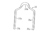
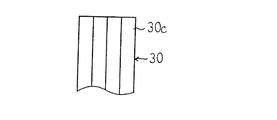
図39において、コイル素線としてのコイルセグメント30は、絶縁被覆された断面が扁平な銅線材を所定の長さに切断し、切断された短尺のコイルメンバーに曲げ加工を施して所定の形状に成形されている。つまり、コイルセグメント30は、断面の長手方向が略平行とされた直線状の一対の直線部30aと、断面の長手方向が頂部で約180°ねじられて直線部30a間を略V字状に連結するターン部30bとからなり、全体として略U字状に成形されている。
【0006】
図40において、固定子コア15は円筒状に成形され、略長方形の断面形状を有するティース15aが径方向内方に突出するように周方向に等角ピッチで複数設けられ、コイルを収容するスロット15bがティース15a間に形成されている。各スロット15bは溝方向が軸方向と平行で、かつ、内周側に開口している。また、絶縁紙19が各スロット15b内に収納されている。ここでは、回転子7が12極であり、固定子8は36個のスロット15bを有しており、毎極毎相当たりのスロット数が1となっている。
コイルセグメント30は、ターン部30bの高さをそろえて、3スロット数離れた対をなす各組のスロット15bに2本ずつリヤ側から挿入されている。各スロット15bには、4本の直線部30aが断面の長手方向を径方向に一致させて、径方向に1列に並んで収納されている。各スロット15bから延出したコイルセグメント30の開放端部側が固定子コア15の端部近傍で周方向に曲げられ、さらにその開放端部30cが断面の長手方向を径方向に一致させて軸方向と平行になるように曲げられている。そして、3スロット数離れたスロット15bから延出したコイルセグメント30の開放端部30c同士が径方向に重ねられて溶接され、各相4ターンの3相分の巻線群が構成されている。このように構成された3相分の巻線群が例えばY結線されて固定子コイル16が作製されている。
【0007】
この固定子コイル16のリヤ側のコイルエンド部16bは、コイルセグメント30のターン部30bが固定子コア15のリヤ側で径方向に2列となって周方向に並んで配列されて構成されている。一方、フロント側のコイルエンド部16aは、3スロット数離れた一方のスロット15bの内周側から1番目の位置(以下、1番地という)から延出するコイルセグメント30の開放端部30cと、他方のスロット15bの内周側から2番目の位置(以下、2番地という)から延出するコイルセグメント30の開放端部30cとが径方向に重ねられて溶接されてなる内周側接合部31と、3スロット数離れた一方のスロット15bの内周側から3番目の位置(以下、3番地という)から延出するコイルセグメント30の開放端部30cと、他方のスロット15bの内周側から4番目の位置(以下、4番地という)から延出するコイルセグメント30の開放端部30cとが径方向に重ねられて溶接されてなる外周側接合部32とが、径方向に2列となって、周方向に並んで配列されて構成されている。
【0008】
ここで、従来の固定子8の製造方法について図41乃至図48を参照しつつ説明する。
まず、図41に示されるように、絶縁被覆された扁平な銅線材をニッパ等で所定の長さに切断し、コイルメンバー29を得る。
ついで、このコイルメンバー29を曲げ加工によりU字状に成形して図42に示されるコイル素線としてのコイルセグメント30を得る。
【0009】
そして、ターン部30bの高さをそろえて、3スロット数離れた対をなす各組のスロット15bにコイルセグメント30を2本ずつリヤ側から挿入する。この時、各スロット15bには、4本の直線部30aが断面の長手方向を径方向に一致させて、径方向に1列に並んで収納される。その後、各スロット15bから延出したコイルセグメント30の開放端部側を固定子コア15の端部近傍で周方向に曲げ、さらにその開放端部30cを断面の長手方向を径方向に一致させて軸方向と平行になるように曲げる。これにより、3スロット数離れた一方のスロット15bの1番地と3番地から延出した2本のコイルセグメント30の開放端部30cと、他方のスロット15bの2番地と4番地から延出した2本のコイルセグメント30の開放端部30cとが、図43および図44に示されるように、径方向に1列に並ぶ。
【0010】
ついで、図45および図46に示されるように、挟み込み治具27を一直線に並べ、治具27の先端同士を突き合わせて4本のコイルセグメント30の端部側を保持する。そして、内周側の2本のコイルセグメント30の開放端部30c同士をアークを使用したティグ溶接により溶融接合する。同様に、外周側の2本のコイルセグメント30の開放端部30c同士をアークを使用したティグ溶接により溶融接合する。これにより、図47および図48に示されるように、内周側溶接部31と外周側溶接部32とが得られる。そして、各開放端部30c同士を溶接することにより、各相4ターンの3相分の巻線群が得られる。なお、溶接時の発熱は挟み込み治具27を介して放熱用治具28に伝達して放熱され、コイルセグメント30の被膜焼けが防止される。
さらに、このように作製された3相分の巻線群が例えばY結線されて固定子コイル16が作製される。
【0011】
【発明が解決しようとする課題】
この従来の交流発電機の固定子においては、線材をニッパ等で切断して得られた短尺のコイルメンバー29を曲げ加工してU字状のコイルセグメント30を成形している。このコイルメンバー29の切断面のサイド部には、図41に示されるように、切断に起因する膨れAとエッジBが生じている。そして、膨れAとエッジBはコイルメンバー29の外形形状より大きいので、コイルセグメント30をスロット15bに挿入する際に、膨れAが干渉してスロットへのコイル挿入性が低下してしまうとともに、エッジBが絶縁紙19を傷つけて、絶縁不良を発生してしまう。そこで、生産性および信頼性を低下させてしまうという問題があった。
また、コイルセグメント30の開放端部30cに被覆されている絶縁被膜が除去されていないので、溶接性が悪化して、エンジンの振動などにより接合部分の外れが発生し、信頼性を低下させる原因になっていた。
また、コイルセグメント30の開放端部30cの外形が縮小されていないので、コイルエンド群16aでは、接合する開放端部30c同士が径方向に1列に並んで密接して配置され、溶接スペースが少ない状態となってしまう。その結果、例えば内周側の2本のコイルセグメント30の開放端部30cを溶接する際に、溶接時の熱が外周側のコイルセグメント30の開放端部30cに伝わり、外周側の開放端部30cを巻き込んで溶接してしまう恐れがあり、生産性を低下させてしまうことになる。さらに、アークが溶接する2本のコイルセグメント30の開放端部30cの境界面に集中しにくくなり、溶融面積が少なくなってしまうので、十分な溶接強度が得られず、エンジンの振動などにより接合部分の外れが発生し、信頼性を低下させる原因になっていた。また、接合部の電気抵抗が大きくなり、発電時の出力電流による発熱量が多くなり、温度上昇による出力低下の原因になっていた。
また、溶融面積を確保するために溶接時間を長くすると、接合部にできる溶接玉が大きくなりすぎ、振動によりレヤショートを発生させる原因となり、信頼性を低下させることになる。
【0012】
この発明は、上記のような課題を解決するためになされたもので、線材に外形縮小部を形成した後、線材を外形縮小部で切断してコイルメンバーを形成するようにし、生産性および信頼性を向上させることができる交流発電機の固定子の製造方法を得ることを目的とする。
【0013】
【課題を解決するための手段】
この発明に係る交流発電機の固定子の製造方法は、絶縁被膜が扁平な断面を有する電気導体に被覆されてなる線材を所定長さに切断してコイルメンバーを形成する工程と、上記コイルメンバーを屈曲加工して所定形状のコイル素線を形成する工程と、所定数の上記コイル素線を固定子コアに装着する工程と、上記固定子コアに装着されたそれぞれの上記コイル素線の端部同士を溶接して所定ターン数の巻線群を形成する工程とを有する交流発電機の固定子の製造方法において、上記線材の各切断部位を略中心として長さ方向の所定範囲にわたって外形縮小部を形成する工程を備えたものである。そして、本交流発電機の固定子の製造方法では、上記外形縮小部を形成する工程は、上記電気導体の幅方向両端部を上記切断部位を略中心として長さ方向の所定範囲にわたって上記絶縁被膜とともに除去して上記幅縮小部を形成する工程と、上記幅縮小部の厚さ方向両面の上記絶縁被膜を除去する工程とを備えており、上記幅縮小部が、上記素線を圧延して上記切断部位を略中心として長さ方向の所定範囲にわたって厚み縮小部を形成し、その後プレスカット工法を用いて上記厚み縮小部の上記電気導体の幅方向両端部を上記絶縁被膜とともに切断して形成されているものである。
【0019】
また、上記幅縮小部は、断面積が長さ方向の両端から中央に向かって漸次減少する形状に形成されているものである。
【0021】
また、上記外形縮小部における上記絶縁被膜を切削加工により除去するようにしたものである。
【0022】
また、上記外形縮小部における上記絶縁被膜を火炎燃焼させた後、生成された炭化物をブラッシング除去するようにしたものである。
【0023】
また、上記外形縮小部における上記絶縁被膜をレーザ照射により焼きとり除去するようにしたものである。
【0024】
また、上記外形縮小部における上記絶縁被膜を溶剤により溶解除去するようにしたものである。
【0025】
この発明に係る交流発電機の固定子の製造方法は、絶縁被膜が扁平な断面を有する電気導体に被覆されてなる線材を所定長さに切断してコイルメンバーを形成する工程と、上記コイルメンバーを屈曲加工して所定形状のコイル素線を形成する工程と、所定数の上記コイル素線を固定子コアに装着する工程と、上記固定子コアに装着されたそれぞれの上記コイル素線の端部同士を溶接して所定ターン数の巻線群を形成する工程とを有する交流発電機の固定子の製造方法において、上記線材の各切断部位を略中心として長さ方向の所定範囲にわたって外形縮小部を形成する工程を備えたものである。そして、本交流発電機の固定子の製造方法では、上記外形縮小部を形成する工程は、上記電気導体の幅方向両端部を上記切断部位を略中心として長さ方向の所定範囲にわたって上記絶縁被膜とともに除去して上記幅縮小部を形成する工程と、上記幅縮小部の厚さ方向両面の上記絶縁被膜を除去する工程とを備えており、上記幅縮小部を形成する工程では、上記切断部位を略中心として長さ方向の所定範囲にわたって上記線材を円形断面の丸状に成形して上記幅縮小部を形成した後、該幅縮小部の上記絶縁被膜を機械剥離するようにし、上記絶縁被膜が機械剥離された上記幅縮小部を扁平形状に成形する工程をさらに備えているものである。
【0026】
また、上記コイルメンバーもしくは上記コイル素線の両端部の角部を加熱溶融して消失させて滑らかな先端形状にする工程を備えたものである。
【0027】
また、上記コイル素線は、所定スロット数離れた一対の直線部間を略V字状のターン部で連結してなる略U字状に形成されているものである。
【0028】
また、上記コイル素線は、直線部が所定スロットピッチで配列され、隣り合う上記直線部の端部同士が略V字状のターン部で連結されて波状の連続線に形成されているものである。
【0032】
【発明の実施の形態】
以下、この発明の実施の形態を図について説明する。
実施の形態1.
図1はこの発明の実施の形態1に係る交流発電機の固定子の固定子コイルに適用される線材を示す斜視図、図2は図1のII−II矢視断面図、図3はこの発明の実施の形態1に係る交流発電機の固定子の製造方法における線材に外形縮小部を形成した状態を示す斜視図、図4は図3のIV−IV矢視断面図、図5は図4のA部拡大図、図6はこの発明の実施の形態1に係る交流発電機の固定子の製造方法における線材を切断してコイルメンバーを形成した状態を示す斜視図、図7はこの発明の実施の形態1に係る交流発電機の固定子の製造方法におけるコイルメンバーに曲げ加工を施して形成されたコイルセグメントを示す斜視図、図8および図9はそれぞれこの発明の実施の形態1に係る交流発電機の固定子の製造方法における固定子コアに挿入されたコイルセグメントの開放端部の配列状態を説明する上面図および側面図、図10および図11はそれぞれこの発明の実施の形態1に係る交流発電機の固定子の製造方法におけるコイルセグメントの開放端部の溶接工程を説明する上面図および側面図、図12および図13はそれぞれこの発明の実施の形態1に係る交流発電機の固定子の製造方法におけるコイルセグメントの開放端部の溶接状態を説明する上面図および側面図、図14はこの発明の実施の形態1に係る交流発電機の固定子の製造方法で製造された固定子のフロント側要部を示す斜視図である。
【0033】
ここで、この実施の形態1による固定子の製造方法を図1乃至図13を参照しつつ説明する。
まず、図1および図2に示されるように、矩形断面を有する扁平な銅等の電気導体39に絶縁被膜41を被覆して形成された線材40が用意される。この線材40は、例えば電気導体39の幅および厚みが2.5mmおよび1.5mm、絶縁被膜41の厚みが0.04mm、角部の曲率半径(R)が 0.4mmのものを用いている。
そして、切削加工により、この線材40の所定長さ毎に線材40の幅方向の両面および厚み方向の両面を長さ方向の所定範囲にわたって切削寸法(D)分だけ切削除去する。これにより、線材40の幅方向および厚み方向のそれぞれの両端部の電気導体39の一部が絶縁被膜41とともに除去され、図3および図4に示されるように、外形縮小部42が得られる。この切削寸法(D)は、図5に示されるように、角部の絶縁被膜41が除去される最小寸法であり、被膜厚み(δ)および角部の曲率半径(D)の大きさによって決まり、D = R - (R-δ)/21/2で与えられる。この例では、切削寸法(D)は、0.145mmである。
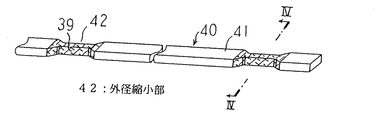
ついで、線材40を各外形縮小部42の長さ方向の真ん中で切断し、所定長さのコイルメンバー44を得る。このコイルメンバー44は、図6に示されるように、両端部の幅が狭く、かつ、厚みが薄い外形形状をなし、両端部の絶縁被膜41が除去されて溶接部45を構成している。
さらに、コイルメンバー44にねじりを加えた曲げ加工を施し、コイル素線としてのコイルセグメント50を得る。このコイルセグメント50は、図7に示されるように、一対の直線部50aを略V字状のターン部50bで連結する略U字状に成形されている。そして、コイルメンバー44の溶接部45がコイルセグメント50の開放端部50cを構成している。なお、コイルセグメント50は、開放端部50c(溶接部45)の幅が狭く、かつ、厚みが薄く形成されている点を除いて、図39に示されるコイルセグメント30と同様に構成されている。
【0034】
そして、ターン部50bの高さをそろえて、3スロット数離れた対をなす各組のスロット15bにコイルセグメント50を2本ずつリヤ側から挿入する。この時、各スロット15bには、4本の直線部50aが断面の長手方向を径方向に一致させて、径方向に1列に並んで収納される。その後、各スロット15bから延出したコイルセグメント50の開放端部側を固定子コア15の端部近傍で周方向に曲げ、さらにその開放端部50cを断面の長手方向を径方向に一致させて軸方向と平行になるように曲げる。これにより、3スロット数離れた一方のスロット15bの1番地と3番地から延出した2本のコイルセグメント50の開放端部50cと、他方のスロット15bの2番地と4番地から延出した2本のコイルセグメント50の開放端部50cとが、図8および図9に示されるように、径方向に1列に並ぶ。
【0035】
ついで、図10および図11に示されるように、挟み込み治具27を一直線に並べ、治具27の先端同士を突き合わせて4本のコイルセグメント50の端部側を保持する。そして、内周側の2本のコイルセグメント50の開放端部50c同士をアークを使用したティグ溶接により溶融接合する。同様に、外周側の2本のコイルセグメント50の開放端部50c同士をアークを使用したティグ溶接により溶融接合する。これにより、図12および図13に示されるように、内周側溶接部51と外周側溶接部52とが得られる。そして、各開放端部50c同士を溶接することにより、各相4ターンの3相分の巻線群が得られる。さらに、3相分の巻線群が例えばY結線されて固定子コイル61となる。これにより、図14に示されるように、固定子コイル61が固定子コア15に巻装された固定子60が得られる。
【0036】
このように構成された固定子コイル61は、多数本のコイルセグメント50が開放端部50c同士を接合されて、3スロット毎にスロット15b内でスロット深さ方向に内層と外層とを交互に採るように波状に固定子コア15に巻装されている。そして、固定子コイル61のリヤ側のコイルエンド群は、図示されていないが、コイルセグメント50のターン部50bが固定子コア15のリヤ側で径方向に2列となって周方向に並んで配列されて構成されている。一方、フロント側のコイルエンド群61aは、3スロット数離れた一方のスロット15bの1番地から延出するコイルセグメント50の開放端部50cと、他方のスロット15bの2番地から延出するコイルセグメント50の開放端部50cとが径方向に重ねられて溶接されてなる内周側接合部51と、3スロット数離れた一方のスロット15bの3番地から延出するコイルセグメント50の開放端部50cと、他方のスロット15bの4番地から延出するコイルセグメント50の開放端部50cとが径方向に重ねられて溶接されてなる外周側接合部52とが、径方向に2列となって、周方向に並んで配列されて構成されている。
このように作製された固定子60は、固定子8に代えて交流発電機に搭載され、同様に動作する。
【0037】
この実施の形態1によれば、線材40に外形縮小部42を形成した後、線材40を外形縮小部42で切断してコイルメンバー44を得るようにしているので、外形縮小部42の切断面のサイド部に生じる膨れやエッジは線材40の外形寸法より小さくなる。そこで、コイルセグメント50をスロット15bに挿入する際に、膨れやエッジがスロット15bに干渉したり、絶縁紙19を傷付けたりすることが防止される。これにより、スロットへのコイル挿入性が向上し、かつ、絶縁不良の発生が抑えられるようになり、生産性および信頼性を向上させることができる。
また、切削加工により線材40の幅方向両端部の電気導体39が絶縁被膜41とともに切削除去されて幅縮小部を形成しているので、絶縁被膜41を除去すべき面積が減少され、絶縁被膜41の除去工程の時間が短縮される。
また、幅縮小部の上下面(厚み方向の両面)に切削加工を施して絶縁被膜41を除去しているので、幅縮小部の形成と絶縁被膜41の除去とを同一の加工方法で連続して行うことができ、加工時間の短縮が図られる。
また、切削寸法(D)がD = R - (R-δ)/21/2を満足するように設定されているので、角部の絶縁被膜41を確実に除去できるとともに、削りすぎによる溶接不良の発生を抑えることができる。
【0038】
また、コイルエンド群16aにおいて、コイルセグメント50の開放端部50cがその断面の長手方向(幅方向)を径方向に一致させて、径方向に1列に並んで配置され、U字状のコイルセグメント50の開放端部50c(溶接部45)が幅を狭められて成形されているので、コイルセグメント50の開放端部50c間に所定の間隙が形成され、溶接スペースが確保される。
そこで、例えば内周側の2本のコイルセグメント50の開放端部50cを溶接する際に、溶接時の熱が外周側のコイルセグメント50の開放端部50cに伝わりにくくなり、外周側の開放端部50cを巻き込んで溶接することが抑えられ、生産性が向上される。
また、接合される開放端部50cが十分に溶融されるので、溶接面積が確保される。さらに、接合される開放端部50cの絶縁被膜41が除去されているので、被膜残りに起因する溶接性の悪化がない。そこで、十分な溶接強度が得られ、エンジンの振動などにより接合部分の外れを防止することができ、信頼性が向上される。また、接合部の電気抵抗が小さくなり、発電時の出力電流による発熱量を抑えることができ、温度上昇による出力低下を防止できる。
さらに、溶接時に熱を与える部分の容積が小さくなるので、溶接時間が短くなり、溶接部にできる溶接玉を小さくできる。その結果、内周側接合部51と外周側接合部52との隙間が確保されるので、振動によるレヤショートの発生が抑制され、信頼性が向上される。
【0039】
なお、上記実施の形態1では、径方向に並ぶ4本の開放端部50cを挟み込み治具27で一括して挟み込み、内周側の2本の開放端部50cを溶接し、さらに外周側の2本の開放端部50cを溶接するものとしているが、径方向に並ぶ4本の開放端部50cを2本ずつ挟み込み治具27で挟み込んで溶接するようにしてもよい。即ち、内周側の2本の開放端部50cを挟み込み治具27で挟み込んで溶接し、ついで外周側の2本の開放端部50cを挟み込み治具27で挟み込んで溶接するようにしてもよい。
【0040】
実施の形態2.
図15はこの発明の実施の形態2に係る交流発電機の固定子の製造方法における線材に幅縮小部を形成した状態を示す斜視図、図16は図15のXVI−XVI矢視断面図、図17はこの発明の実施の形態2に係る交流発電機の固定子の製造方法における線材の幅縮小部の絶縁被膜を除去した状態を示す斜視図である。なお、この実施の形態2では、切削加工に代えてプレスカット工法を用いて線材40に幅縮小部43Aを形成している点を除いて、上記実施の形態1と同様に構成されている。
【0041】
この実施の形態2では、プレスカット工法を用いて、線材40の所定長さ毎に幅方向両端部の電気導体39を絶縁被膜41とともに長さ方向の所定範囲にわたって切断し、図15および図16に示されるように、幅縮小部43Aを形成する。
ついで、線材40の幅縮小部43Aの上下面(厚み方向の両面)に切削加工を施して、絶縁被膜41を除去する。
これにより、図17に示されるように、絶縁被膜41が除去された外形縮小部42Aを有する線材40が得られる。
このように作製された線材40を各外形縮小部42Aの長さ方向の真ん中で切断し、上記実施の形態1と同様に、両端部の幅が狭く、かつ、厚みの薄い外形形状をなし、両端部の絶縁被膜41が除去された溶接部を有するコイルメンバーを得る。そして、上記実施の形態1と同様に、コイルメンバーを曲げ加工して作製された略U字状のコイルセグメントを固定子コアに組み込み、固定子が製造される。
【0042】
このように、この実施の形態2では、プレスカット工法により線材40に幅縮小部43Aを形成している点を除いて上記実施の形態1と同様に構成されているので、上記実施の形態1と同様の効果が得られる。
また、この実施の形態2によれば、幅縮小部43Aを形成するに当たり、切削加工に比べて加工が容易なプレスカット工法を用いているので、実施の形態1に比べてより生産性が高められる。
【0043】
実施の形態3.
上記実施の形態1、2では、線材40の所定長さ毎に形成された幅縮小部の上下面に切削加工を施して絶縁被膜41を除去するものとしているが、この実施の形態3では、線材40の幅縮小部に火炎を照射して絶縁被膜41を燃焼させ、その後絶縁被膜41が燃焼されて生成される炭化物をブラッシングにより除去するものとしている。
この実施の形態3によれば、火炎により絶縁被膜41を燃焼させているので、絶縁被膜41を非接触で、簡易に、かつ、確実に除去できる。そこで、溶接部の被膜残りがなくなり、被膜残りに起因する溶接性の悪化を未然に防止できる。
【0044】
実施の形態4.
上記実施の形態3では、線材40の幅縮小部に火炎を照射して絶縁被膜41を燃焼させ、その後絶縁被膜41が燃焼されて生成される炭化物をブラッシングにより除去するものとしているが、この実施の形態4では、線材40の幅縮小部にレーザを照射して絶縁被膜41を焼きとり除去するものとしている。
この実施の形態4によれば、レーザの照射により絶縁被膜41を除去しているので、上記実施の形態3のように絶縁被膜41の炭化物がレーザ照射部に残らない。そこで、ブラッシングによる炭化物除去工程が不要となり、工程の短縮が図られる。
【0045】
実施の形態5.
上記実施の形態3では、線材40の幅縮小部に火炎を照射して絶縁被膜41を燃焼させ、その後絶縁被膜41が燃焼されて生成される炭化物をブラッシングにより除去するものとしているが、この実施の形態5では、幅縮小部が露出するように線材40にマスキングを施し、線材40を苛性ソーダあるいは苛性カリなどの溶剤に浸漬して絶縁被膜41を溶解除去するものとしている。
この実施の形態5によれば、線材40の幅縮小部を溶剤に浸漬させて絶縁被膜41を溶解除去しているので、幅縮小部の絶縁被膜41を確実に除去できる。
【0046】
ここで、幅縮小部が形成された線材40を所定長さに切断してコイルメンバーを作製した後、多数本のコイルメンバーを束ね、それらの幅縮小部を溶剤に浸漬させて幅縮小部の絶縁被膜41を溶解除去するようにしてもよい。この場合、多数本のコイルメンバーの幅縮小部の絶縁被膜が一括して除去されるので、絶縁被膜の除去工程を短縮することができる。
【0047】
実施の形態6.
この実施の形態6では、プレスカット工法により線材40の幅方向両端部の電気導体39を切断除去する前に、線材40の幅縮小部の形成部位を圧延するようにしたものである。
なお、この実施の形態6は、幅縮小部の形成工程の前に、圧延工程を実施している点を除いて、上記実施の形態2と同様である。
【0048】
ここで、この実施の形態6による特徴部分を図18乃至図21を参照しつつ説明する。
まず、図18および図19に示されるように、線材40の所定長さ毎に線材40を長さ方向の所定範囲にわたって圧延して厚み縮小部46を形成する。
ついで、プレスカット工法を用いて、この線材40の所定長さ毎に線材40の幅方向両端部の電気導体39を絶縁被膜41とともに長さ方向の所定範囲にわたって切断除去し、図20および図21に示されるように、幅縮小部43Bを形成する。
このように作製された線材40は、上記実施の形態2と同様に、幅縮小部43Bの絶縁被膜41を除去して外形縮小部を形成し、線材40を該外形縮小部の長さ方向の中央部で切断してコイルメンバーが得られる。そして、コイルメンバーを屈曲して略U字状のコイルセグメントに形成し、該コイルセグメントが固定子コアに組み込まれて、固定子が製造される。
【0049】
この実施の形態6によれば、幅縮小部43Bの形成工程前に線材40の圧延工程を導入しているので、プレスカット工法による幅縮小部形成工程において、カットする方向のコイル面積が大きくなり、線材40を確実にプレスカットすることができる。また、コイルセグメントの開放端部の厚みが薄くなっているので、スロット15bへのコイル挿入性が向上される。
【0050】
実施の形態7.
この実施の形態7では、図22に示されるように、プレスカット工法により線材40の厚み縮小部を長さ方向の中央部が細くなるように切断除去して幅縮小部43Cを形成している。そして、幅縮小部43Cの絶縁被膜41を除去して外形縮小部を形成し、線材40を該外形縮小部の長さ方向の中央部で切断してコイルメンバーを作製している。
なお、この実施の形態7は、厚み縮小部の長さ方向の中央部を細くするようにプレスカットしている点を除いて、上記実施の形態6と同様である。
【0051】
この実施の形態7によれば、線材40が厚み縮小部の長さ方向の中央部を細くするように切断除去されて幅縮小部43Cを形成しているので、線材40を外形縮小部の長さ方向の中央部で切断して作製されたコイルメンバーの両端部の溶接部は、先細り形状を有している。そこで、スロット15bへのコイル挿入性が向上されるとともに、溶接時にアークを溶接部の先端に集中させることができ、溶接性をさらに高めることができる。
【0052】
実施の形態8.
この実施の形態8では、図23および図24に示されるように、プレスにより線材40の所定長さ毎に線材40を長さ方向の所定範囲にわたって絞って円形断面の幅縮小部43Dを形成する。ついで、図25に示されるように、3台の機械ツール55を幅縮小部43Dを取り囲むように配置し、各機械ツール55を回転させるとともに、3台の機械ツール55を一体として幅縮小部43D周りに回転させることにより、この線材40の幅縮小部43Dの絶縁被膜41を除去して外形縮小部を形成している。
【0053】
この実施の形態8によれば、幅縮小部43Dが円形断面に成形されているので、機械ツール55を用いても、絶縁被膜41を完全に除去でき、被膜残りに起因する溶接性の悪化を防止することができる。
【0054】
実施の形態9.
この実施の形態9では、上記実施の形態8で示したように機械ツール55で幅縮小部43Dの絶縁被膜41を除去した後、幅縮小部43Dを圧延して矩形断面の外形縮小部42Eを形成する圧延工程を追加している。
この実施の形態9によれば、図26および図27に示されるように、矩形断面の外形縮小部42Eが得られるので、上記実施の形態8に比べて、接合される溶接部同士の接触面積が増大し、接合強度を大きくすることができる。そこで、車両やエンジンの振動による接合部の外れが防止される。
【0055】
実施の形態10.
この実施の形態10では、図28に示されるように、線材40を外形縮小部の長さ方向の中央部で切断してコイルメンバー44Aを形成した後、コイルメンバー44Aの両端の溶接部45Aを加熱溶融するようにしている。
なお、この実施の形態10は、コイルメンバー44Aの両端の溶接部45Aを加熱溶融している点を除いて、上記実施の形態2と同様に構成されている。
【0056】
この実施の形態10によれば、コイルメンバー44Aの両端の溶接部45Aを加熱溶融しているので、溶接部45Aの角部が溶融し、滑らかな外形形状となる。そこで、線材を外形縮小部の長さ方向中央部で切断してコイルメンバー44Aを作製したときに、外形縮小部の切断面のサイド部に生じた膨れやエッジが消失し、スロットへのコイル挿入性がさらに向上される。
ここで、コイルメンバーからコイルセグメントを成形した後、コイルセグメントの両端の開放端部を加熱溶融しても、同様の効果が得られる。
【0057】
実施の形態11.
上記実施の形態1〜10では、短尺のコイルメンバーをU字状に屈曲加工して得られたコイルセグメント50を用いて作製した固定子コイルに適用するものとしているが、この実施の形態11では、長尺のコイルメンバーを波形に屈曲加工して得られたコイル素線を用いて作製した固定子コイルに適用するものである。
【0058】
まず、1相分の固定子巻線群の巻線構造について図29を参照して具体的に説明する。なお、図29中、固定子コアの一端側の配線を実線で、他端側の配線を点線で示している。また、固定子コア62は円筒状に成形され、略長方形の断面形状を有するティース62aが径方向内方に突出するように周方向に等角ピッチで複数設けられ、コイルを収容するスロット62bがティース62a間に形成されている。各スロット62bは溝方向が軸方向と平行で、かつ、内周側に開口している。ここでは、固定子コア62には、回転子の磁極数(16)に対応して、後述する3相固定子巻線64を2組収容するように、96本のスロット62bが形成されており、毎極毎相当たりスロット数が2となっている。
【0059】
1相分の固定子巻線群65は、それぞれ1本のコイルメンバー70を波状に成形されたコイル素線としての第1乃至第4巻線71〜74から構成されている。そして、第1巻線71は、1本のコイルメンバー70を、スロット番号の1番から91番まで6スロットおきに、スロット62b内の内周側から1番目の位置(1番地)と内周側から2番目の位置(2番地)とを交互に採るように波巻きして構成されている。第2巻線72は、コイルメンバー70を、スロット番号の1番から91番まで6スロットおきに、スロット62b内の2番地と1番地とを交互に採るように波巻きして構成されている。第3巻線73は、コイルメンバー70を、スロット番号の1番から91番まで6スロットおきに、スロット62b内の内周側から3番目の位置(3番地)と内周側から4番目の位置(4番地)とを交互に採るように波巻きして構成されている。第4巻線74は、コイルメンバー70を、スロット番号の1番から91番まで6スロットおきに、スロット62b内の4番地と3番地とを交互に採るように波巻きして構成されている。
【0060】
そして、固定子コア62の一端側において、スロット番号の1番の2番地から延出する第2巻線72の端部72aと、スロット番号の91番の1番地から延出する第2巻線72の端部72bとが接合されて1ターンの巻線が形成され、さらにスロット番号の1番の4番地から延出する第4巻線74の端部74aと、スロット番号の91番の3番地から延出する第4巻線74の端部74bとが接合されて、1ターンの巻線が形成されている。
また、固定子コア62の他端側において、スロット番号の1番の1番地から延出する第1巻線71の端部71aと、スロット番号の91番の2番地から延出する第1巻線71の端部71bとが接合されて1ターンの巻線が形成され、さらにスロット番号の1番の3番地から延出する第3巻線73の端部73aと、スロット番号の91番の4番地から延出する第3巻線73の端部73bとが接合されて1ターンの巻線が形成されている。
これにより、第1乃至第4巻線71〜74は、それぞれ、1本のコイルメンバー70を6スロット毎にスロット62b内でスロット深さ方向に内層と外層とを交互に採るように巻装されてなる1ターンの巻線を構成している。そして、各スロット62b内には、コイルメンバー70が扁平な断面(長方形断面)の長手方向を径方向に揃えて径方向に1列に4本並んで配列されている。
【0061】
ついで、スロット番号の61番の1番地と67番の2番地とから固定子コア62の一端側に延出する第1巻線71のコイルメンバー70の部分が切断され、スロット番号の61番の3番地と67番の4番地とから固定子コア62の一端側に延出する第3巻線73のコイルメンバー70の部分が切断される。さらに、スロット番号の67番の1番地と73番の2番地とから固定子コア62の一端側に延出する第2巻線72のコイルメンバー70の部分が切断され、スロット番号の67番の3番地と73番の4番地とから固定子コア62の一端側に延出する第4巻線74のコイルメンバー70の部分が切断される。
そして、第1巻線71の切断端71cと第2巻線72の切断端72cとが接合され、第3巻線73の切断端73cと第1巻線71の切断端71dとが接合され、第4巻線74の切断端74cと第2巻線72の切断端72dとが接合されて、第1乃至第4巻線71〜74を直列接続してなる4ターンの1相分の固定子巻線群65が形成されている。
なお、第1巻線71の切断端71cと第2巻線72の切断端72cとの接合部、第3巻線73の切断端73cと第1巻線71の切断端71dとの接合部、第4巻線74の切断端74cと第2巻線72の切断端72dとの接合部が渡り結線接続部となり、第3巻線73の切断端73dと第4巻線74の切断端74dとがそれぞれ中性点(N)および口出し線(O)となる。
【0062】
同様にして、第1乃至第4巻線71〜74が巻装されるスロット62bを1つづつずらして6相分の固定子巻線群65が形成されている。そして、図30に示されるように、固定子巻線群65が3相分づつY結線されて2組の3相固定子巻線64からなる固定子コイル63を形成し、各3相固定子巻線64がそれぞれ整流器12に接続されている。各整流器12の直流出力は並列に接続されて合成される。
【0063】
ここで、第1乃至第4巻線71〜74を構成するそれぞれのコイルメンバー70は、1つのスロット62bから固定子コア62の端面側に延出し、折り返されて6スロット離れたスロット62bに入るように波巻きに巻装されている。そして、それぞれのコイルメンバー70は、6スロット毎に、スロット深さ方向(径方向)に関して、内層と外層とを交互に採るように巻装されている。そして、第1巻線71と第2巻線72とは電気角で180°ずれて反転巻装されている。同様に、第3巻線73と第4巻線74とは電気角で180°ずれて反転巻装されている。
固定子コア62の端面側に延出して折り返されたコイルメンバー70のターン部がコイルエンドを形成している。そこで、固定子コア62の両端において、ほぼ同一形状に形成されたターン部が周方向に、かつ、径方向に互いに離間して、2列となって周方向に整然と配列されてフロント側およびリヤ側のコイルエンド群を形成している。
【0064】
ついで、固定子60Aの組立方法について図1乃至図4および図31乃至図37を参照しつつ具体的に説明する。
まず、図1および図2に示されるように、矩形断面を有する扁平な銅等の電気導体39に絶縁被膜41を被覆して形成された線材40が用意される。そして、切削加工により、この線材40の所定長さ毎に線材40の幅方向の両面および厚み方向の両面を長さ方向の所定範囲にわたって切削寸法分だけ切削除去する。これにより、線材40の幅方向および厚み方向のそれぞれの両端部の電気導体39の一部が絶縁被膜41とともに除去され、図3および図4に示されるように、外形縮小部42が得られる。ついで、外形縮小部42の長さ方向の中央部で線材40を切断し、長尺のコイルメンバー70を作製する。この時、コイルメンバー70の両端部は、図31に示されるように、幅が狭く、厚みが薄く形成されている。
このようにして作製された12本のコイルメンバー70を、図31に示されるように、同時に同一平面上で雷状に折り曲げ形成する。ついで、図32に矢印で示されるように、直角方向に治具にて折り畳んでゆき、図33に示される巻線アッセンブリ80を作製する。
なお、各コイルメンバー70は折り曲げされて、図34に示されるように、ターン部81aで連結された直線部81bが6スロットピッチ(6P)で配列された波状パターンのコイル素線81に成形されている。そして、隣り合う直線部81bが、ターン部81aにより、コイルメンバー70の幅(W)分ずらされている。素線アッセンブリ80は、このような波状パターンに形成された2本のコイル素線81を図35に示されるように6スロットピッチずらして直線部81bを重ねて配列された素線対が1スロットピッチづつずらして6対配列されて構成されている。そして、コイル素線81の端部が素線アッセンブリ80の両端の両側に6本づつ延出されている。また、コイルエンドを構成するターン部81aが素線アッセンブリ80の両側部に整列されて配列されている。ここで、各コイル素線81が、図38で示した第1乃至第4巻線71〜74に相当している。
また、台形形状のスロット83aが所定のピッチ(電気角で30°)で形成された磁性材料のSPCC材を所定枚数積層し、その外周部をレーザ溶接して、図36に示されるように、直方体の積層鉄心83を作製する。
【0065】
そして、図37の(a)に示されるように、インシュレータ19が積層鉄心83のスロット83aに装着され、2つの素線アッセンブリ80の各直線部81bを各スロット83a内に重ねて押し入れる。これにより、図37の(b)に示されるように、2つの素線アッセンブリ80が積層鉄心83に装着される。コイル素線81の直線部81bは、インシュレータ19により積層鉄心83と絶縁されてスロット83a内に径方向に4本並んで収納されている。そして、2つの素線アッセンブリ80は、重なって積層鉄心83に装着されている。
ついで、積層鉄心83を丸め、その端面同士を当接させて溶接し、図37の(c)に示されるように、円筒状の固定子コア62を得る。
そして、図38に示される結線方法に基づいて、各コイル素線81の端部同士を結線して固定子巻線群65を形成する。
ここで、渡り結線、口出し線および中性点用のコイル素線81の切断端における絶縁被膜41の除去には、レーザ照射による絶縁被膜41の焼きとりが適している。
【0066】
このように、この実施の形態11によれば、線材40に外形縮小部42を形成した後、線材40を外形縮小部42で切断してコイルメンバー70を得るようにしているので、コイルメンバー70を波状に折り曲げて成形されたコイル素線81の端部は、絶縁被膜41が除去され、その幅が狭く、かつ、厚みが薄く形成されている。
また、1相分の固定子巻線群65を構成する第1乃至第4巻線71〜74はそれぞれ端部同士を溶接して1ターンの巻線に形成されている。この時、第1および第3巻線71、73の端部71a、71b、73a、73bは、固定子コア62の他端側で、その断面の長手方向(幅方向)を径方向に一致させて、径方向に1列に並んで配置され、第2および第4巻線72、74の端部72a、72b、74a、74bは、固定子コア62の一端側で、その断面の長手方向(幅方向)を径方向に一致させて、径方向に1列に並んで配置されている。そして、コイル素線81、即ち第1乃至第4巻線の各端部が幅を狭められて成形されているので、端部71a、71bと端部73a、73bとの間、同様に端部72a、72bと端部74a、74bとの間に所定の間隙が形成され、溶接スペースが確保される。
従って、この実施の形態11においても、上記実施の形態1と同様の効果が得られる。
【0067】
また、この実施の形態11では、1本のコイル素線81から1ターンの巻線を形成しているので、多数本のU字状のコイルセグメント50を直列に接続して1ターンの巻線を形成している上記実施の形態1〜10に比べて、接合箇所が著しく削減され、固定子の生産性を向上させることができるとともに、溶接による電気導体の軟化がなく、固定子としての剛性が高くなり、磁気騒音を低減させることができる。
また、コイル素線81のターン部81aによりコイルエンド群を構成しているので、コイルセグメント50の開放端部50c同士を接合してコイルエンド群を構成している上記実施の形態1〜10に比べて、コイルエンドの高さを低くすることができる。これにより、コイルエンド群における通風抵抗が小さくなり、回転子の回転に起因する風音を低減でき、さらにコイルの漏れリアクタンスが減少し、出力・効率が向上される。
さらに、12本のコイル素線81から巻線アッセンブリ80を形成しているので、2組の巻線アッセンブリ80を固定子コア62に2列に巻装することで6相分の固定子巻線群65が巻装されることになり、組立性を著しく向上させることができる。
【0068】
なお、上記各実施の形態では、切削加工やプレスカット工法により線材40の幅方向両端部の電気導体39を絶縁被膜41とともに除去して幅縮小部を形成した後、幅縮小部の絶縁被膜41を除去して外形縮小部を形成するものとしているが、線材40の切断部位を略中心として長さ方向の所定範囲にわたって絶縁被膜41を除去して外形縮小部を形成するようにしてもよい。この場合、外形縮小部の外形は絶縁被膜41の厚み分縮小されており、外形縮小部の切断面のサイド部に生じた膨れやエッジに起因する不具合を低減できる。そして、この線材から形成されたセグメントコイルやコイル素線を固定子コアに装着した際に、セグメントコイルやコイル素線の端部間が径方向で離間し、溶接スペースが確保される。なお、絶縁被膜41を除去する際には、例えば上記実施の形態3〜5で述べた火炎による絶縁被膜の燃焼除去方法、レーザ照射による絶縁被膜の燃焼除去方法、溶剤による絶縁被膜の溶解除去方法などを用いることができる。
また、上記各実施の形態では、コイルセグメント50やコイル素線81の直線部50a、81aをスロット15b、62b内に径方向に1列に4本ずつ配列するものとしているが、スロット内に配列される直線部の本数はこれに限定されるものではない。
【0069】
【発明の効果】
この発明は、以上のように構成されているので、以下に記載されるような効果を奏する。
【0070】
この発明によれば、絶縁被膜が扁平な断面を有する電気導体に被覆されてなる線材を所定長さに切断してコイルメンバーを形成する工程と、上記コイルメンバーを屈曲加工して所定形状のコイル素線を形成する工程と、所定数の上記コイル素線を固定子コアに装着する工程と、上記固定子コアに装着されたそれぞれの上記コイル素線の端部同士を溶接して所定ターン数の巻線群を形成する工程とを有する交流発電機の固定子の製造方法において、上記線材の各切断部位を略中心として長さ方向の所定範囲にわたって外形縮小部を形成する工程を備えたので、生産性および信頼性を向上させることができる交流発電機の固定子の製造方法が得られる。
【0072】
また、上記外形縮小部を形成する工程は、上記電気導体の幅方向両端部を上記切断部位を略中心として長さ方向の所定範囲にわたって上記絶縁被膜とともに除去して上記幅縮小部を形成する工程と、上記幅縮小部の厚さ方向両面の上記絶縁被膜を除去する工程とを備えているので、コイル素線の端部同士を溶接する際の溶接スペースが確保されるとともに、幅縮小部の絶縁被膜の除去面積が減少され、絶縁被膜の除去工程の時間が短縮される。
【0075】
また、上記幅縮小部が、上記素線を圧延して上記切断部位を略中心として長さ方向の所定範囲にわたって厚み縮小部を形成し、その後プレスカット工法を用いて上記厚み縮小部の上記電気導体の幅方向両端部を上記絶縁被膜とともに切断して形成されているので、スロットへの挿入性が向上される。
【0076】
また、上記幅縮小部は、断面積が長さ方向の両端から中央に向かって漸次減少する形状に形成されているので、溶接時にアークを溶接部に集中でき、溶接性が高められるとともに、溶接強度が向上される。
【0077】
また、上記切断部位を略中心として長さ方向の所定範囲にわたって上記線材を円形断面の丸状に成形して上記幅縮小部を形成した後、該幅縮小部の上記絶縁被膜を機械剥離するようにしたので、機械ツールを用いても絶縁被膜を確実に除去でき、被膜残りに起因する溶接性の悪化が防止される。
【0078】
また、上記絶縁被膜が機械剥離された上記幅縮小部を扁平形状に成形する工程を備えたので、スロットへの挿入性が向上される。
【0079】
また、上記外形縮小部における上記絶縁被膜を切削加工により除去するようにしたので、絶縁被膜を確実に除去でき、被膜残りに起因する溶接性の悪化が防止される。
【0080】
また、上記外形縮小部における上記絶縁被膜を火炎燃焼させた後、生成された炭化物をブラッシング除去するようにしたので、絶縁被膜の除去工程が短縮される。
【0081】
また、上記外形縮小部における上記絶縁被膜をレーザ照射により焼きとり除去するようにしたので、ブラッシング工程が不要となり、絶縁被膜の除去工程がさらに短縮される。
【0082】
また、上記外形縮小部における上記絶縁被膜を溶剤により溶解除去するようにしたので、絶縁被膜を確実に除去でき、被膜残りに起因する溶接性の悪化が防止される。
【0083】
また、上記コイルメンバーもしくは上記コイル素線の両端部の角部を加熱溶融して消失させて滑らかな先端形状にする工程を備えたので、スロットへのコイル挿入性が向上される。
【0084】
また、上記コイル素線は、所定スロット数離れた一対の直線部間を略V字状のターン部で連結してなる略U字状に形成されているので、円筒状の固定子コアを作製した後、コイル素線を固定子コアに挿入して固定子コイルを作製でき、固定子の製造が容易となる。
【0085】
また、上記コイル素線は、直線部が所定スロットピッチで配列され、隣り合う上記直線部の端部同士が略V字状のターン部で連結されて波状の連続線に形成されているので、接合箇所が大幅に削減され、かつ、コイル素線の固定子コアへの装着工程が簡易となり、生産性が向上されるとともに、コイルエンドが連続線のターン部となり、コイルエンド群の軸方向高さを低くすることができる。
【図面の簡単な説明】
【図1】 この発明の実施の形態1に係る交流発電機の固定子の固定子コイルに適用される線材を示す斜視図である。
【図2】 図1のII−II矢視断面図である。
【図3】 この発明の実施の形態1に係る交流発電機の固定子の製造方法における線材に外形縮小部を形成した状態を示す斜視図である。
【図4】 図3のIV−IV矢視断面図である。
【図5】 図4のA部を拡大した図である。
【図6】 この発明の実施の形態1に係る交流発電機の固定子の製造方法における線材を切断してコイルメンバーを形成した状態を示す斜視図である。
【図7】 この発明の実施の形態1に係る交流発電機の固定子の製造方法におけるコイルメンバーに曲げ加工を施して形成されたコイルセグメントを示す斜視図である。
【図8】 この発明の実施の形態1に係る交流発電機の固定子の製造方法における固定子コアに挿入されたコイルセグメントの開放端部の配列状態を説明する上面図である。
【図9】 この発明の実施の形態1に係る交流発電機の固定子の製造方法における固定子コアに挿入されたコイルセグメントの開放端部の配列状態を説明する側面図である。
【図10】 この発明の実施の形態1に係る交流発電機の固定子の製造方法におけるコイルセグメントの開放端部の溶接工程を説明する上面図である。
【図11】 この発明の実施の形態1に係る交流発電機の固定子の製造方法におけるコイルセグメントの開放端部の溶接工程を説明する側面図である。
【図12】 この発明の実施の形態1に係る交流発電機の固定子の製造方法におけるコイルセグメントの開放端部の溶接状態を説明する上面図である。
【図13】 この発明の実施の形態1に係る交流発電機の固定子の製造方法におけるコイルセグメントの開放端部の溶接状態を説明する側面図である。
【図14】 この発明の実施の形態1に係る交流発電機の固定子の製造方法で製造された固定子のフロント側要部を示す斜視図である。
【図15】 この発明の実施の形態2に係る交流発電機の固定子の製造方法における線材に幅縮小部を形成した状態を示す斜視図である。
【図16】 図15のXVI−XVI矢視断面図である。
【図17】 この発明の実施の形態2に係る交流発電機の固定子の製造方法における線材の幅縮小部の絶縁被膜を除去した状態を示す斜視図である。
【図18】 この発明の実施の形態6に係る交流発電機の固定子の製造方法における線材に厚み縮小部を形成した状態を示す斜視図である。
【図19】 図18のXIX−XIX矢視断面図である。
【図20】 この発明の実施の形態6に係る交流発電機の固定子の製造方法における線材に幅縮小部を形成した状態を示す斜視図である。
【図21】 図20のXXI−XXI矢視断面図である。
【図22】 この発明の実施の形態7に係る交流発電機の固定子の製造方法における線材に幅縮小部を形成した状態を示す斜視図である。
【図23】 この発明の実施の形態8に係る交流発電機の固定子の製造方法における線材に幅縮小部を形成した状態を示す斜視図である。
【図24】 図23のXXIV−XXIV矢視断面図である。
【図25】 この発明の実施の形態8に係る交流発電機の固定子の製造方法における線材の幅縮小部の絶縁被膜の除去工程を説明する図である。
【図26】 この発明の実施の形態9に係る交流発電機の固定子の製造方法における線材に外形縮小部を形成した状態を示す斜視図である。
【図27】 図26のXXVII−XXVII矢視断面図である。
【図28】 この発明の実施の形態10に係る交流発電機の固定子の製造方法におけるコイルメンバーの要部を示す斜視図である。
【図29】 この発明の実施の形態11に係る交流発電機の固定子における固定子コイルの1相分の結線状態を説明する平面図である。
【図30】 この発明の実施の形態11に係る交流発電機の固定子の回路図である。
【図31】 この発明の実施の形態11に係る交流発電機の固定子における固定子コイルを構成する巻線群の製造工程を説明する図である。
【図32】 この発明の実施の形態11に係る交流発電機の固定子における固定子コイルを構成する巻線群の製造工程を説明する図である。
【図33】 この発明の実施の形態11に係る交流発電機の固定子における固定子コイルを構成する巻線アッセンブリを示す図である。
【図34】 この発明の実施の形態11に係る交流発電機の固定子における固定子コイルを構成するコイル素線の要部を示す斜視図である。
【図35】 この発明の実施の形態11に係る交流発電機の固定子における固定子コイルを構成するコイル素線の配列を説明する図である。
【図36】 この発明の実施の形態11に係る交流発電機の固定子における固定子コアを構成する積層鉄心を示す斜視図である。
【図37】 この発明の実施の形態11に係る交流発電機の固定子の製造工程を説明する工程断面図である。
【図38】 一般的な交流発電機を示す断面図である。
【図39】 従来の固定子におけるコイルセグメントを示す平面図である。
【図40】 従来の固定子の要部をフロント側から見た斜視図である。
【図41】 従来の交流発電機の固定子の製造方法における線材を切断してコイルメンバーを形成した状態を示す斜視図である。
【図42】 従来の交流発電機の固定子の製造方法におけるコイルメンバーに曲げ加工を施して形成されたコイルセグメントを示す平面図である。
【図43】 従来の交流発電機の固定子の製造方法における固定子コアに挿入されたコイルセグメントの開放端部の配列状態を説明する上面図である。
【図44】 従来の交流発電機の固定子の製造方法における固定子コアに挿入されたコイルセグメントの開放端部の配列状態を説明する側面図である。
【図45】 従来の交流発電機の固定子の製造方法におけるコイルセグメントの開放端部の溶接工程を説明する上面図である。
【図46】 従来の交流発電機の固定子の製造方法におけるコイルセグメントの開放端部の溶接工程を説明する側面図である。
【図47】 従来の交流発電機の固定子の製造方法におけるコイルセグメントの開放端部の溶接状態を説明する上面図である。
【図48】 従来の交流発電機の固定子の製造方法におけるコイルセグメントの開放端部の溶接状態を説明する側面図である。
【符号の説明】
15、62 固定子コア、15b、62b スロット、16、63 固定子コイル、39 電気導体、40 線材、41 絶縁被膜、42、42A、42E 外形縮小部、43A、43B、43C、43D 幅縮小部、44、44A、70 コイルメンバー、46 厚み縮小部、50 コイルセグメント(コイル素線)、50a 直線部、50b ターン部、60、60A 固定子、64 3相固定子巻線、65 固定子巻線群、71 第1巻線、72 第2巻線、73 第3巻線、74 第4巻線、81 コイル素線、81a ターン部、81b 直線部。[0001]
BACKGROUND OF THE INVENTION
The present invention relates to an alternator stator driven by, for example, an internal combustion engine and a method for manufacturing the same, and in particular, a coil strand having a flat cross section formed into a predetermined shape is wound around a stator core, and the coil strand Fixing an alternator with a stator coil constructed by welding the ends togetherOf childIt relates to a manufacturing method.
[0002]
[Prior art]
FIG. 38 is a cross-sectional view showing a configuration of a general AC generator.
In this AC generator, a Randall-type rotor 7 is rotatably mounted via a
The
[0003]
The rotor 7 is provided so as to cover the rotor coil 13 that generates a magnetic flux by passing an electric current, and a pair of
The
[0004]
In the AC generator configured as described above, a current is supplied from a battery (not shown) to the rotor coil 13 via the
[0005]
Next, the structure of the
In FIG. 39, a
[0006]
In FIG. 40, the
Two
[0007]
The
[0008]
Here, a conventional method for manufacturing the
First, as shown in FIG. 41, a flat copper wire covered with insulation is cut into a predetermined length with a nipper or the like to obtain a
Next, the
[0009]
Then, two
[0010]
Next, as shown in FIGS. 45 and 46, the sandwiching jigs 27 are arranged in a straight line, and the ends of the four
Furthermore, the
[0011]
[Problems to be solved by the invention]
In this conventional alternator stator, a
In addition, since the insulating coating covering the
Also, the
Further, if the welding time is lengthened in order to ensure the melted area, the weld balls that can be formed in the joint portion become too large, causing a layer short due to vibration, and reducing the reliability.
[0012]
The present invention has been made to solve the above-described problems, and after forming an outer reduced portion on a wire, the wire is cut at the outer reduced portion to form a coil member, thereby improving productivity and reliability. AC generator fixing that can improve the performanceOf childIt aims at obtaining a manufacturing method.
[0013]
[Means for Solving the Problems]
The method for manufacturing a stator of an alternator according to the present invention includes a step of cutting a wire rod covered with an electric conductor having an insulating coating having a flat cross section into a predetermined length to form a coil member, and the coil member Forming a coil wire having a predetermined shape by bending the wire, attaching a predetermined number of the coil wires to the stator core, and ends of the coil wires attached to the stator core And a step of forming a winding group having a predetermined number of turns by welding the portions to each other, and reducing the outer shape over a predetermined range in the length direction with each cutting portion of the wire approximately at the center The process of forming a part is provided.In the method of manufacturing the stator of the alternating current generator, the step of forming the outer reduced portion includes the insulating coating over a predetermined range in the length direction with the both ends in the width direction of the electric conductor as a substantial center. And removing the insulating coating on both sides in the thickness direction of the width reduced portion, the width reduced portion rolling the element wire. Forming a reduced thickness portion over a predetermined range in the length direction with the cutting site as a substantial center, and then forming both ends of the reduced thickness portion in the width direction of the electric conductor together with the insulating coating using a press-cut method. It is what has been.
[0019]
Moreover, the said width reduction part is formed in the shape where a cross-sectional area reduces gradually toward the center from the both ends of a length direction.
[0021]
Also,The insulating coating in the outer reduced portion was removed by cutting.Is.
[0022]
In addition, the insulating coating in the outer reduced portionAfter burning the flame, brush the generated carbideIt is intended to be removed.
[0023]
In addition, the insulating coating in the outer reduced portionBurning by laser irradiationIt is intended to be removed.
[0024]
In addition, the insulating coating in the outer reduced portionSoluble with solventIt is intended to be removed.
[0025]
The method for manufacturing a stator of an alternator according to the present invention includes a step of cutting a wire rod covered with an electric conductor having an insulating coating having a flat cross section into a predetermined length to form a coil member, and the coil member Forming a coil wire having a predetermined shape by bending the wire, attaching a predetermined number of the coil wires to the stator core, and ends of the coil wires attached to the stator core And a step of forming a winding group having a predetermined number of turns by welding the portions to each other, and reducing the outer shape over a predetermined range in the length direction with each cutting portion of the wire approximately at the center The process of forming a part is provided. In the method of manufacturing the stator of the alternating current generator, the step of forming the outer reduced portion includes the insulating coating over a predetermined range in the length direction with the both ends in the width direction of the electric conductor as a substantial center. And removing the insulating film on both sides in the thickness direction of the width reduced portion, and in the step of forming the width reduced portion, And forming the width-reduced portion by forming the wire rod into a circular shape having a circular cross section over a predetermined range in the length direction with the approximate center as the center, and then mechanically peeling the insulating coating of the reduced-width portion. Is further provided with a step of forming the width-reduced part, which has been mechanically peeled, into a flat shape.Is.
[0026]
Further, the present invention includes a step of heating and melting the corners at both ends of the coil member or the coil element wire so as to make a smooth tip shape.
[0027]
The coil wire is formed in a substantially U-shape formed by connecting a pair of straight portions separated by a predetermined number of slots with a substantially V-shaped turn portion.
[0028]
Further, the coil wire is formed as a wave-like continuous line in which straight portions are arranged at a predetermined slot pitch, and ends of adjacent straight portions are connected by a substantially V-shaped turn portion. is there.
[0032]
DETAILED DESCRIPTION OF THE INVENTION
Embodiments of the present invention will be described below with reference to the drawings.
1 is a perspective view showing a wire applied to a stator coil of a stator of an alternator according to
[0033]
Here, a method of manufacturing the stator according to the first embodiment will be described with reference to FIGS.
First, as shown in FIG. 1 and FIG. 2, a
Then, by cutting, the both sides of the
Next, wire
Further, the
[0034]
Then, two
[0035]
Next, as shown in FIGS. 10 and 11, the sandwiching jigs 27 are arranged in a straight line, the ends of the
[0036]
In the
The
[0037]
According to the first embodiment, the wire 40OutlineAfter forming the reduced
Further, since the
Further, since the insulating
The cutting dimension (D) is D = R-(R-δ) / 21/2Therefore, it is possible to reliably remove the insulating
[0038]
In the
Therefore, for example, when welding the
Moreover, since the
Furthermore, since the volume of the part which gives heat at the time of welding becomes small, welding time becomes short and the welding ball which can be made into a welding part can be made small. As a result, a gap between the inner peripheral side joint 51 and the outer peripheral side joint 52 is ensured, so that the occurrence of a layer short due to vibration is suppressed and the reliability is improved.
[0039]
In the first embodiment, the four
[0040]
15 is a perspective view showing a state in which a width reduction portion is formed in the wire in the method for manufacturing an alternator stator according to
[0041]
In the second embodiment, the
Next, the insulating
As a result, the insulating
Each of the
[0042]
As described above, the second embodiment is configured in the same manner as in the first embodiment except that the
Further, according to the second embodiment, the formation of the
[0043]
Embodiment 3 FIG.
In the first and second embodiments, the insulating
According to the third embodiment, since the insulating
[0044]
Embodiment 4 FIG.
In the third embodiment, the insulating
According to the fourth embodiment, since the insulating
[0045]
In the third embodiment, the insulating
According to the fifth embodiment, since the insulating
[0046]
Here, after the
[0047]
In the sixth embodiment, before the
The sixth embodiment is the same as the second embodiment except that the rolling process is performed before the width reducing portion forming process.
[0048]
Here, characteristic portions according to the sixth embodiment will be described with reference to FIGS.
First, as shown in FIG. 18 and FIG. 19, the
Next, by using a press-cut method, the
The
[0049]
According to this
[0050]
Embodiment 7. FIG.
In the seventh embodiment, as shown in FIG. 22, the width reduced
In addition, this Embodiment 7 is the same as that of the said
[0051]
According to the seventh embodiment, the
[0052]
In the eighth embodiment, as shown in FIGS. 23 and 24, the
[0053]
According to the eighth embodiment, since the
[0054]
In the ninth embodiment, as shown in the eighth embodiment, after the insulating
According to the ninth embodiment, as shown in FIG. 26 and FIG.OutlineSince the reduced
[0055]
In the tenth embodiment, as shown in FIG.OutlineAfter the
The tenth embodiment is configured in the same manner as in the second embodiment except that the welded
[0056]
According to the tenth embodiment, since the welded
Here, after the coil segment is formed from the coil member, the same effect can be obtained by heating and melting the open ends at both ends of the coil segment.
[0057]
Embodiment 11 FIG.
In the said Embodiment 1-10, although it shall apply to the stator coil produced using the
[0058]
First, the winding structure of the stator winding group for one phase will be specifically described with reference to FIG. In FIG. 29, the wiring on one end side of the stator core is indicated by a solid line, and the wiring on the other end side is indicated by a dotted line. Further, the
[0059]
The
[0060]
Then, on one end side of the
Further, on the other end side of the
As a result, the first to
[0061]
Next, a portion of the
Then, the
In addition, a joint portion between the
[0062]
Similarly, a
[0063]
Here, each of the
A turn portion of the
[0064]
Next, a method for assembling the
FirstAs shown in FIGS. 1 and 2, a
As shown in FIG. 31, the twelve
Each
In addition, as shown in FIG. 36, a predetermined number of magnetic SPCC materials in which
[0065]
Then, as shown in FIG. 37 (a), the
Next, the
And based on the connection method shown by FIG. 38, the edge part of each
Here, in order to remove the insulating
[0066]
Thus, according to this eleventh embodiment, the wire 40OutlineAfter forming the reduced
Further, the first to
Therefore, also in this eleventh embodiment, the same effect as in the first embodiment can be obtained.
[0067]
In the eleventh embodiment, since one turn winding is formed from one
Moreover, since the coil end group is comprised by the
Furthermore, since the winding
[0068]
In each of the above embodiments, the
In each of the above embodiments, four
[0069]
【The invention's effect】
Since this invention is comprised as mentioned above, there exists an effect as described below.
[0070]
According to the present invention, the step of forming a coil member by cutting a wire formed by covering an electric conductor having a flat cross section with an insulating coating to a predetermined length, and bending the coil member to form a coil having a predetermined shape A step of forming a strand, a step of mounting a predetermined number of the coil strands on the stator core, and welding the ends of each of the coil strands mounted on the stator core to a predetermined number of turns And a step of forming a winding group of the alternating current generator stator, over a predetermined range in the length direction with each cutting portion of the wire approximately as a center.OutlineSince the process of forming the reduced portion is provided, a method for manufacturing an alternator stator that can improve productivity and reliability can be obtained.
[0072]
Also, aboveOutlineThe step of forming the reduced portion includes the step of removing the both ends in the width direction of the electric conductor together with the insulating coating over a predetermined range in the length direction with the cut portion as a center, and forming the width reduced portion, A step of removing the insulating coating on both sides in the thickness direction of the reduced portion, so that a welding space for welding the ends of the coil wires is secured and the insulating coating of the width reduced portion is removed. The area is reduced, and the time for the insulating film removal process is shortened.
[0075]
In addition, the width reduction portion rolls the wire to form a thickness reduction portion over a predetermined range in the length direction with the cut portion as a center, and then uses the press-cut method to Since both end portions in the width direction of the conductor are cut together with the insulating film, the insertion into the slot is improved.
[0076]
In addition, since the cross-sectional area is formed in a shape in which the cross-sectional area gradually decreases from both ends in the length direction toward the center, the arc can be concentrated on the welded portion during welding, so that the weldability is improved and welding is improved. Strength is improved.
[0077]
Further, after forming the width reduced portion by forming the wire rod into a circular shape having a circular cross section over a predetermined range in the length direction with the cut portion as a substantial center, the insulating coating of the width reduced portion is mechanically peeled off. As a result, the insulating coating can be reliably removed even using a mechanical tool, and deterioration of weldability due to the coating residue is prevented.
[0078]
In addition, since the step of forming the width-reduced portion from which the insulating coating has been mechanically peeled into a flat shape is provided, the insertion into the slot is improved.
[0079]
Also, aboveOutlineSince the insulating coating in the reduced portion is removed by cutting, the insulating coating can be removed reliably, and deterioration of weldability due to the remaining coating is prevented.
[0080]
Also, aboveOutlineSince the generated carbide is brushed and removed after the insulating coating in the reduced portion is flame-combusted, the insulating coating removal process is shortened.
[0081]
Also, aboveOutlineSince the insulating film in the reduced portion is removed by laser irradiation, the brushing process is not necessary, and the insulating film removing process is further shortened.
[0082]
Also, aboveOutlineSince the insulating film in the reduced portion is removed by dissolution with a solvent, the insulating film can be removed reliably, and deterioration of weldability due to the remaining film is prevented.
[0083]
In addition, since the step of heating and melting the corners at both ends of the coil member or the coil strands to make them smooth and having a smooth tip shape, coil insertion into the slot is improved.
[0084]
Further, the coil wire is formed in a substantially U-shape formed by connecting a pair of straight portions separated by a predetermined number of slots with a substantially V-shaped turn portion, so that a cylindrical stator core is manufactured. After that, the coil wire can be inserted into the stator core to produce the stator coil, and the stator can be easily manufactured.
[0085]
In addition, the coil strands are formed in a continuous wavy line in which straight portions are arranged at a predetermined slot pitch, and ends of adjacent straight portions are connected by a substantially V-shaped turn portion. The number of joints is greatly reduced, and the process of attaching the coil wire to the stator core is simplified, productivity is improved, and the coil end becomes a turn portion of the continuous wire, so that the axial height of the coil end group is increased. The thickness can be lowered.
[Brief description of the drawings]
FIG. 1 is a perspective view showing a wire applied to a stator coil of a stator of an alternator according to
FIG. 2 is a cross-sectional view taken along the line II-II in FIG.
FIG. 3 shows a wire in the method of manufacturing an alternator stator according to
4 is a cross-sectional view taken along the line IV-IV in FIG. 3;
5 is an enlarged view of part A in FIG. 4;
FIG. 6 is a perspective view showing a state in which a coil member is formed by cutting a wire in the method of manufacturing an alternator stator according to
FIG. 7 is a perspective view showing a coil segment formed by bending a coil member in the method for manufacturing a stator for an alternator according to
FIG. 8 is a top view for explaining an arrangement state of open ends of coil segments inserted into the stator core in the method for manufacturing a stator for an alternator according to
FIG. 9 is a side view illustrating an arrangement state of open end portions of coil segments inserted into the stator core in the method for manufacturing a stator for an alternator according to
FIG. 10 is a top view for explaining the welding process of the open end portion of the coil segment in the method for manufacturing a stator for an alternator according to
FIG. 11 is a side view for explaining the welding process of the open end of the coil segment in the method for manufacturing the stator for an alternator according to
FIG. 12 is a top view for explaining a welded state of the open end portion of the coil segment in the method for manufacturing the stator for an alternator according to
FIG. 13 is a side view illustrating a welded state of the open end portion of the coil segment in the method for manufacturing a stator for an alternator according to
FIG. 14 is a perspective view showing a main part of the front side of the stator manufactured by the method for manufacturing a stator for an alternator according to
FIG. 15 is a perspective view showing a state in which a reduced width portion is formed in the wire in the method of manufacturing a stator for an alternator according to
16 is a cross-sectional view taken along arrow XVI-XVI in FIG.
FIG. 17 is a perspective view showing a state in which the insulating coating is removed from the width reducing portion of the wire in the method of manufacturing a stator for an alternator according to
FIG. 18 is a perspective view showing a state in which a thickness reducing portion is formed on a wire in a method for manufacturing an alternator stator according to
19 is a cross-sectional view taken along arrow XIX-XIX in FIG.
FIG. 20 is a perspective view showing a state in which a width reducing portion is formed in a wire in a method for manufacturing a stator for an alternator according to
21 is a cross-sectional view taken along arrow XXI-XXI in FIG. 20;
FIG. 22 is a perspective view showing a state in which a reduced width portion is formed in a wire in a method for manufacturing a stator for an alternator according to Embodiment 7 of the present invention;
FIG. 23 is a perspective view showing a state in which a width reducing portion is formed in the wire in the method for manufacturing an alternator stator according to
24 is a cross-sectional view taken along arrow XXIV-XXIV in FIG.
FIG. 25 is a diagram illustrating an insulating film removal step for a wire width reduced portion in the method for manufacturing an alternator stator according to
FIG. 26 shows a wire in a method for manufacturing an alternator stator according to
27 is a sectional view taken along arrow XXVII-XXVII in FIG. 26;
FIG. 28 is a perspective view showing a main part of a coil member in a method for manufacturing a stator for an alternator according to
FIG. 29 is a plan view illustrating a connection state for one phase of a stator coil in a stator of an alternator according to Embodiment 11 of the present invention;
FIG. 30 is a circuit diagram of a stator of an AC generator according to Embodiment 11 of the present invention.
FIG. 31 is a diagram illustrating a manufacturing process of a winding group constituting a stator coil in a stator of an AC generator according to Embodiment 11 of the present invention.
32 is a diagram illustrating a manufacturing process of a winding group constituting the stator coil in the stator of the AC generator according to Embodiment 11 of the present invention. FIG.
FIG. 33 is a diagram showing a winding assembly that constitutes a stator coil in a stator of an alternator according to Embodiment 11 of the present invention;
FIG. 34 is a perspective view showing a main part of a coil wire constituting a stator coil in a stator of an alternator according to Embodiment 11 of the present invention;
FIG. 35 is a diagram for explaining an arrangement of coil wires constituting a stator coil in a stator of an alternator according to Embodiment 11 of the present invention;
FIG. 36 is a perspective view showing a laminated core that constitutes a stator core in the stator of the alternator according to Embodiment 11 of the present invention;
FIG. 37 is a process cross-sectional view illustrating a manufacturing process of the stator of the AC generator according to Embodiment 11 of the present invention.
FIG. 38 is a cross-sectional view showing a general AC generator.
FIG. 39 is a plan view showing a coil segment in a conventional stator.
FIG. 40 is a perspective view of a main part of a conventional stator as viewed from the front side.
FIG. 41 is a perspective view showing a state where a coil member is formed by cutting a wire in a conventional method of manufacturing a stator for an AC generator.
FIG. 42 is a plan view showing a coil segment formed by bending a coil member in a conventional method for manufacturing a stator of an AC generator.
FIG. 43 is a top view for explaining the arrangement of the open ends of the coil segments inserted into the stator core in the conventional method for manufacturing a stator of an AC generator.
FIG. 44 is a side view for explaining an arrangement state of open ends of coil segments inserted into a stator core in a conventional method for manufacturing a stator of an AC generator.
FIG. 45 is a top view for explaining the welding process of the open end portion of the coil segment in the conventional method for manufacturing a stator of an AC generator.
FIG. 46 is a side view for explaining the welding process of the open end portion of the coil segment in the conventional method for manufacturing a stator of an AC generator.
47 is a top view for explaining a welding state of the open end portion of the coil segment in the conventional method for manufacturing a stator of an AC generator. FIG.
FIG. 48 is a side view for explaining a welding state of an open end portion of a coil segment in a conventional method for manufacturing a stator of an AC generator.
[Explanation of symbols]
15, 62 Stator core, 15b, 62b Slot, 16, 63 Stator coil, 39 Electrical conductor, 40 Wire, 41 Insulating coating, 42, 42A, 42EOutlineReduction part, 43A, 43B, 43C, 43D Width reduction part, 44, 44A, 70 Coil member, 46 Thickness reduction part, 50 Coil segment (coil strand), 50a Linear part, 50b Turn part, 60, 60A Stator, 64 3-phase stator winding, 65 stator winding group, 71 1st winding, 72 2nd winding, 73 3rd winding, 74 4th winding, 81 coil element wire, 81a turn part, 81b straight line Department.
Claims (10)
上記線材の各切断部位を略中心として長さ方向の所定範囲にわたって外形縮小部を形成する工程を備え、
上記外形縮小部を形成する工程は、上記電気導体の幅方向両端部を上記切断部位を略中心として長さ方向の所定範囲にわたって上記絶縁被膜とともに除去して上記幅縮小部を形成する工程と、上記幅縮小部の厚さ方向両面の上記絶縁被膜を除去する工程とを備えており、
上記幅縮小部が、上記素線を圧延して上記切断部位を略中心として長さ方向の所定範囲にわたって厚み縮小部を形成し、その後プレスカット工法を用いて上記厚み縮小部の上記電気導体の幅方向両端部を上記絶縁被膜とともに切断して形成されていることを特徴とする交流発電機の固定子の製造方法。A step of forming a coil member by cutting a wire formed by covering an electric conductor having a flat cross section with an insulating coating to a predetermined length, and a step of bending the coil member to form a coil wire of a predetermined shape And a step of attaching a predetermined number of the coil wires to the stator core, and welding ends of the coil wires attached to the stator core to form a winding group having a predetermined number of turns. A method of manufacturing an alternator stator having a process of:
Comprising the step of forming an outer reduced portion over a predetermined range in the length direction with each cutting portion of the wire approximately as a center ,
The step of forming the outer reduced portion is a step of removing the both ends in the width direction of the electric conductor together with the insulating film over a predetermined range in the length direction with the cut portion as a center to form the width reduced portion; A step of removing the insulating coating on both sides in the thickness direction of the width reduced portion,
The width-reduced portion rolls the strand to form a thickness-reduced portion over a predetermined range in the length direction with the cut portion as a substantial center, and then uses a press-cut method of the electrical conductor of the thickness-reduced portion. A method of manufacturing a stator for an AC generator, wherein both ends in the width direction are cut together with the insulating coating .
上記線材の各切断部位を略中心として長さ方向の所定範囲にわたって外形縮小部を形成する工程を備え、
上記外形縮小部を形成する工程は、上記電気導体の幅方向両端部を上記切断部位を略中心として長さ方向の所定範囲にわたって上記絶縁被膜とともに除去して上記幅縮小部を形成する工程と、上記幅縮小部の厚さ方向両面の上記絶縁被膜を除去する工程とを備えており、
上記幅縮小部を形成する工程では、上記切断部位を略中心として長さ方向の所定範囲にわたって上記線材を円形断面の丸状に成形して上記幅縮小部を形成した後、該幅縮小部の上記絶縁被膜を機械剥離するようにし、
上記絶縁被膜が機械剥離された上記幅縮小部を扁平形状に成形する工程をさらに備えていることを特徴とする交流発電機の固定子の製造方法。A step of forming a coil member by cutting a wire formed by covering an electric conductor having a flat cross section with an insulating coating to a predetermined length, and a step of bending the coil member to form a coil wire of a predetermined shape And a step of attaching a predetermined number of the coil wires to the stator core, and welding ends of the coil wires attached to the stator core to form a winding group having a predetermined number of turns. A method of manufacturing an alternator stator having a process of:
Comprising the step of forming an outer reduced portion over a predetermined range in the length direction with each cutting portion of the wire approximately as a center ,
The step of forming the outer reduced portion is a step of removing the both ends in the width direction of the electric conductor together with the insulating film over a predetermined range in the length direction with the cut portion as a center to form the width reduced portion; A step of removing the insulating coating on both sides in the thickness direction of the width reduced portion,
In the step of forming the width reduced portion, after forming the width reduced portion by forming the wire rod into a circular shape with a circular cross section over a predetermined range in the length direction with the cutting site as a substantial center, The above insulating coating is mechanically peeled off,
A method of manufacturing a stator of an alternator , further comprising a step of forming the width reduced portion from which the insulating coating has been mechanically peeled into a flat shape .
Priority Applications (5)
| Application Number | Priority Date | Filing Date | Title |
|---|---|---|---|
| JP2000046175A JP4462392B2 (en) | 2000-02-23 | 2000-02-23 | Method of manufacturing an alternator stator |
| US09/711,073 US6865796B1 (en) | 2000-02-23 | 2000-11-14 | Method of manufacturing a stator for an alternator with reduced conductor portions |
| DE60044896T DE60044896D1 (en) | 2000-02-23 | 2000-11-22 | Method for producing a stator for an alternator |
| EP00125218A EP1128530B1 (en) | 2000-02-23 | 2000-11-22 | Method for manufacturing a stator for an alternator |
| KR10-2001-0003425A KR100406101B1 (en) | 2000-02-23 | 2001-01-20 | Stator for an alternator and a method for the manufacture thereof |
Applications Claiming Priority (1)
| Application Number | Priority Date | Filing Date | Title |
|---|---|---|---|
| JP2000046175A JP4462392B2 (en) | 2000-02-23 | 2000-02-23 | Method of manufacturing an alternator stator |
Publications (3)
| Publication Number | Publication Date |
|---|---|
| JP2001238385A JP2001238385A (en) | 2001-08-31 |
| JP2001238385A5 JP2001238385A5 (en) | 2007-02-08 |
| JP4462392B2 true JP4462392B2 (en) | 2010-05-12 |
Family
ID=18568645
Family Applications (1)
| Application Number | Title | Priority Date | Filing Date |
|---|---|---|---|
| JP2000046175A Expired - Lifetime JP4462392B2 (en) | 2000-02-23 | 2000-02-23 | Method of manufacturing an alternator stator |
Country Status (5)
| Country | Link |
|---|---|
| US (1) | US6865796B1 (en) |
| EP (1) | EP1128530B1 (en) |
| JP (1) | JP4462392B2 (en) |
| KR (1) | KR100406101B1 (en) |
| DE (1) | DE60044896D1 (en) |
Cited By (2)
| Publication number | Priority date | Publication date | Assignee | Title |
|---|---|---|---|---|
| CN109980823A (en) * | 2017-12-27 | 2019-07-05 | 丰田自动车株式会社 | The stator of rotating electric machine and the manufacturing method of stator coil |
| US10958048B2 (en) | 2016-03-17 | 2021-03-23 | Honda Motor Co., Ltd. | Peeling device and method |
Families Citing this family (60)
| Publication number | Priority date | Publication date | Assignee | Title |
|---|---|---|---|---|
| JP3709823B2 (en) * | 2001-10-05 | 2005-10-26 | 株式会社デンソー | Vehicle alternator |
| JP3889630B2 (en) * | 2002-01-21 | 2007-03-07 | 三菱電機株式会社 | Winding joining method for rotating electrical machines |
| JP3680801B2 (en) * | 2002-02-27 | 2005-08-10 | 株式会社デンソー | Winding joining method for rotating electrical machines |
| JP4019951B2 (en) | 2002-03-01 | 2007-12-12 | 株式会社デンソー | Manufacturing method of winding of rotating electrical machine and processing method of winding recess |
| JP3775317B2 (en) * | 2002-03-20 | 2006-05-17 | 株式会社デンソー | Manufacturing method of winding of rotating electric machine |
| DE10213383A1 (en) * | 2002-03-26 | 2003-10-16 | Bosch Gmbh Robert | Method for in particular mechanical winding of an electrical winding on a winding support |
| JP2004032897A (en) | 2002-06-25 | 2004-01-29 | Denso Corp | Segments-sequentially-joined stator coil for rotary electric machine and its manufacturing method |
| JP3982446B2 (en) * | 2003-04-16 | 2007-09-26 | 株式会社日立製作所 | Manufacturing method of rotating electrical machine |
| JP3970202B2 (en) | 2003-05-07 | 2007-09-05 | 三菱電機株式会社 | Manufacturing method of electric wire for rotating electrical machine |
| JP4654068B2 (en) * | 2005-05-24 | 2011-03-16 | 日立オートモティブシステムズ株式会社 | Bonded electric wire, method of processing the bonded electric wire, rotating electric machine stator, rotating electric machine stator manufacturing method, and bonded electric wire manufacturing apparatus |
| JP4412330B2 (en) * | 2007-02-09 | 2010-02-10 | 株式会社デンソー | Stator winding of rotating electric machine and method of manufacturing the same |
| JP5137615B2 (en) * | 2008-02-25 | 2013-02-06 | 三菱電機株式会社 | Winding structure of permanent magnet type rotating electrical machine |
| JP4461399B2 (en) * | 2008-03-05 | 2010-05-12 | 株式会社デンソー | Coil assembly braiding machine for rotating electrical machines |
| JP4577588B2 (en) * | 2008-04-18 | 2010-11-10 | 株式会社デンソー | Method for manufacturing coil assembly of rotating electrical machine |
| JP4600508B2 (en) * | 2008-04-21 | 2010-12-15 | 株式会社デンソー | Stator manufacturing method for inner rotor type rotating electrical machine |
| JP4600580B2 (en) * | 2008-04-21 | 2010-12-15 | 株式会社デンソー | Stator coil manufacturing method |
| JP5167939B2 (en) * | 2008-05-12 | 2013-03-21 | 株式会社デンソー | Method for manufacturing coil assembly of rotating electrical machine |
| US7694909B1 (en) | 2009-06-05 | 2010-04-13 | Remy Technologies, L.L.C. | Method of winding a flexible core |
| US7712697B1 (en) * | 2009-06-05 | 2010-05-11 | Remy Technologies, L.L.C. | Core winding apparatus and method of winding a core |
| US20100133945A1 (en) * | 2009-06-05 | 2010-06-03 | Remy International Inc. | Segmented stator core winding apparatus and method of winding a segmented stator core |
| JP5233901B2 (en) * | 2009-08-07 | 2013-07-10 | アイシン・エィ・ダブリュ株式会社 | Bending method |
| JP5429132B2 (en) * | 2009-10-23 | 2014-02-26 | 株式会社デンソー | Manufacturing method of stator of rotating electric machine and stator of rotating electric machine |
| US8614530B2 (en) * | 2009-12-17 | 2013-12-24 | Remy Technologies, L.L.C. | Stator core for an electric machine |
| JP5781754B2 (en) * | 2010-11-24 | 2015-09-24 | トヨタ自動車株式会社 | Rotating electric machine |
| JP5136920B2 (en) * | 2010-11-26 | 2013-02-06 | 株式会社デンソー | Rotating electrical machine stator for vehicles |
| US8671559B2 (en) | 2011-04-27 | 2014-03-18 | GM Global Technology Operations LLC | System for joining stator wires |
| JP2012244640A (en) * | 2011-05-13 | 2012-12-10 | Denso Corp | Rotating electric machine |
| JP2013021896A (en) * | 2011-07-14 | 2013-01-31 | Hitachi Automotive Systems Ltd | Rotating electric machine and method for manufacturing stator coil of rotating electric machine |
| US20130033145A1 (en) * | 2011-08-02 | 2013-02-07 | Remy Technologies, Llc | Electric machine module insulation system and method |
| US20130187494A1 (en) * | 2012-01-25 | 2013-07-25 | Remy Technologies, L.L.C. | Stator assembly for an electric machine |
| JP6056317B2 (en) * | 2012-09-21 | 2017-01-11 | トヨタ自動車株式会社 | Stator |
| JP5954137B2 (en) * | 2012-11-22 | 2016-07-20 | トヨタ自動車株式会社 | Stator manufacturing method and stator manufacturing apparatus |
| WO2014115703A1 (en) * | 2013-01-22 | 2014-07-31 | 三菱電機株式会社 | Rectangular wire edgewise-bending processing device and rectangular wire edgewise-bending processing method |
| JP6116298B2 (en) * | 2013-03-15 | 2017-04-19 | 本田技研工業株式会社 | Arrangement structure of rotating electrical machine unit |
| JP5680159B1 (en) * | 2013-08-29 | 2015-03-04 | 本田技研工業株式会社 | Manufacturing method of rotating electrical machine |
| JP6021772B2 (en) * | 2013-09-26 | 2016-11-09 | 三菱電機株式会社 | Rotating electric machine |
| DE102013225130A1 (en) * | 2013-12-06 | 2015-06-11 | Continental Automotive Gmbh | Winding segment for forming a winding of an electric machine, method for producing a winding segment |
| JP5635674B1 (en) * | 2013-12-18 | 2014-12-03 | 武延 本郷 | Coil and coil manufacturing equipment |
| CN103929020B (en) * | 2014-03-28 | 2017-06-16 | 福建闽光电机制造有限公司 | A kind of paint scraping device of rectangle enamel-cover line end |
| JP6402517B2 (en) * | 2014-07-14 | 2018-10-10 | 株式会社デンソー | Method for manufacturing conductor member, conductor member, stator, and motor |
| DE102014215304A1 (en) * | 2014-08-04 | 2016-02-04 | Ksb Aktiengesellschaft | Rotor, reluctance machine and rotor manufacturing method |
| DE102014218224B4 (en) * | 2014-09-11 | 2017-11-02 | Continental Automotive Gmbh | Winding support, electric motor with a winding support |
| US10622735B2 (en) | 2014-10-15 | 2020-04-14 | Rittal Gmbh & Co. Kg | Cable sequence for a wiring of an electrical circuit, method for production and use |
| JP6299723B2 (en) * | 2015-10-23 | 2018-03-28 | トヨタ自動車株式会社 | Stator coil forming method |
| DE102017104932A1 (en) * | 2016-03-08 | 2017-09-14 | Grob-Werke Gmbh & Co. Kg | Manufacturing method for a stator |
| IT201600115749A1 (en) * | 2016-11-16 | 2018-05-16 | Atop Spa | Method and equipment for manufacturing a stator of a dynamoelectric machine |
| CN109923771B (en) * | 2016-11-18 | 2022-10-04 | 日立安斯泰莫株式会社 | Method for manufacturing stator |
| CN108282041B (en) | 2017-01-06 | 2020-04-21 | 株式会社东芝 | Coil for rotating electric machine |
| DE102017222577A1 (en) * | 2017-12-13 | 2019-06-13 | Robert Bosch Gmbh | Method for stripping an electrical conductor |
| US11018545B2 (en) | 2018-08-03 | 2021-05-25 | Ford Global Technologies, Llc | Electric machine winding assembly |
| JP7131373B2 (en) * | 2018-12-26 | 2022-09-06 | トヨタ自動車株式会社 | Coil wire welding method |
| JP2020123997A (en) * | 2019-01-29 | 2020-08-13 | 日立オートモティブシステムズ株式会社 | Rotary electric machine and manufacturing method of rotary electric machine |
| JP7315334B2 (en) * | 2019-02-05 | 2023-07-26 | 日立Astemo株式会社 | Rotating electric machine and vehicle |
| JP7516776B2 (en) * | 2019-07-09 | 2024-07-17 | 株式会社プロテリアル | How to cut rectangular conductor wire |
| JP7460284B2 (en) | 2020-09-23 | 2024-04-02 | ダイハツ工業株式会社 | Manufacturing method of rectangular wire |
| JP7560372B2 (en) * | 2021-01-29 | 2024-10-02 | トヨタ自動車株式会社 | Stator manufacturing method and clamping jig |
| US11962205B2 (en) * | 2021-03-16 | 2024-04-16 | The Timken Company | Mechanical strength of connection of wound rotor generator/motor |
| DE102021109872A1 (en) | 2021-04-20 | 2022-10-20 | Dr. Ing. H.C. F. Porsche Aktiengesellschaft | Method of manufacturing a stator assembly |
| WO2023223690A1 (en) * | 2022-05-18 | 2023-11-23 | 三菱電機株式会社 | Gripping device, gripping method, and manufacturing method for rotating electrical machine |
| CN116073603B (en) * | 2023-03-13 | 2023-06-27 | 邦迪智能装备(河南)有限公司 | Coil end sharp angle forming device of flat wire motor |
Family Cites Families (29)
| Publication number | Priority date | Publication date | Assignee | Title |
|---|---|---|---|---|
| US1822261A (en) * | 1927-06-28 | 1931-09-08 | Vincent G Apple | Bar wound field element |
| US1917482A (en) * | 1927-11-18 | 1933-07-11 | Herbert F Apple | Armature coil |
| US1834926A (en) | 1930-02-05 | 1931-12-08 | Vincent G Apple | Method of making winding loops for bar wound armatures |
| FR1265020A (en) | 1960-08-12 | 1961-06-23 | Thomson Houston Comp Francaise | Improvements in the manufacture of windings for electrical machines |
| US3364801A (en) * | 1967-03-06 | 1968-01-23 | Raymond Poturnicki | Wire center stripper die assembly |
| JPS5438501A (en) | 1977-09-02 | 1979-03-23 | Hitachi Ltd | Armature winding end forming device |
| JPS5523773A (en) | 1978-08-09 | 1980-02-20 | Hitachi Ltd | Shaping of armature winding |
| US4352305A (en) * | 1980-08-05 | 1982-10-05 | General Electric Company | Apparatus for stripping insulation from wire |
| JPH0687644B2 (en) | 1986-06-25 | 1994-11-02 | 三菱電機株式会社 | Electric motor coil manufacturing method |
| JPH0238144U (en) * | 1988-09-08 | 1990-03-14 | ||
| KR950000799B1 (en) * | 1990-08-15 | 1995-02-02 | 가부시끼가이샤 히다찌세이사꾸쇼 | Motor and the connection of stator winding with lead wire |
| JPH0556609A (en) * | 1991-08-08 | 1993-03-05 | Hitachi Ltd | Automatic connecting equipment for lead wire of rotating machine |
| JPH05111731A (en) * | 1991-10-21 | 1993-05-07 | Mitsubishi Electric Corp | Device for skinning and cutting flat wire stock |
| JPH0654498A (en) * | 1992-07-24 | 1994-02-25 | Nippondenso Co Ltd | Commutator-type rotary electrical equipment |
| JPH06141496A (en) * | 1992-10-23 | 1994-05-20 | Nippondenso Co Ltd | Armature coil of commutator type rotating electric machine |
| DE4321007A1 (en) * | 1993-06-24 | 1995-01-05 | Kloeckner Moeller Gmbh | Assembled cable, in particular for control cabinet and control engineering, process for its processing and processing device therefor |
| JP3521444B2 (en) | 1993-07-26 | 2004-04-19 | 神鋼電機株式会社 | Bus information system |
| JP3012225U (en) * | 1994-12-08 | 1995-06-13 | 日東造機株式会社 | Air core coil |
| US5508571A (en) * | 1994-12-12 | 1996-04-16 | General Motors Corporation | Neutral connection for wire wound stator |
| US5778512A (en) * | 1994-12-19 | 1998-07-14 | Nippondenso Co., Ltd. | Manufacturing method for a rotor of an electric rotary machine |
| JP3477962B2 (en) * | 1994-12-19 | 2003-12-10 | 株式会社デンソー | Method for manufacturing rotor of rotating electric machine |
| EP1237254B1 (en) * | 1997-05-26 | 2008-06-04 | Denso Corporation | Alternator for vehicle |
| JP3407643B2 (en) * | 1997-05-26 | 2003-05-19 | 株式会社デンソー | AC generator for vehicles |
| JPH11164530A (en) * | 1997-11-27 | 1999-06-18 | Toshiba Corp | Structure of end part of rotor coil and manufacture thereof |
| US6181043B1 (en) * | 1997-12-10 | 2001-01-30 | Denso Corporation | Alternator for vehicle |
| JP3724951B2 (en) | 1998-05-25 | 2005-12-07 | 株式会社デンソー | Vehicle alternator |
| JP3641557B2 (en) * | 1998-11-30 | 2005-04-20 | 旭精機工業株式会社 | Wire material processing method |
| US6687974B1 (en) * | 1999-12-27 | 2004-02-10 | Mitsubishi Denki Kabushiki Kaisha | Method for manufacturing an alternator |
| JP2002119003A (en) * | 2000-10-10 | 2002-04-19 | Mitsubishi Electric Corp | Stator for dynamo-electric machine, and manufacturing method thefor |
-
2000
- 2000-02-23 JP JP2000046175A patent/JP4462392B2/en not_active Expired - Lifetime
- 2000-11-14 US US09/711,073 patent/US6865796B1/en not_active Expired - Lifetime
- 2000-11-22 DE DE60044896T patent/DE60044896D1/en not_active Expired - Lifetime
- 2000-11-22 EP EP00125218A patent/EP1128530B1/en not_active Expired - Lifetime
-
2001
- 2001-01-20 KR KR10-2001-0003425A patent/KR100406101B1/en active IP Right Grant
Cited By (4)
| Publication number | Priority date | Publication date | Assignee | Title |
|---|---|---|---|---|
| US10958048B2 (en) | 2016-03-17 | 2021-03-23 | Honda Motor Co., Ltd. | Peeling device and method |
| CN109980823A (en) * | 2017-12-27 | 2019-07-05 | 丰田自动车株式会社 | The stator of rotating electric machine and the manufacturing method of stator coil |
| CN109980823B (en) * | 2017-12-27 | 2021-02-19 | 丰田自动车株式会社 | Stator of rotating electric machine and method for manufacturing stator coil |
| US10978925B2 (en) | 2017-12-27 | 2021-04-13 | Toyota Jidosha Kabushiki Kaisha | Stator of rotary electric machine and method of manufacturing stator coil |
Also Published As
| Publication number | Publication date |
|---|---|
| EP1128530A3 (en) | 2003-08-06 |
| EP1128530A2 (en) | 2001-08-29 |
| KR100406101B1 (en) | 2003-11-15 |
| KR20010085296A (en) | 2001-09-07 |
| JP2001238385A (en) | 2001-08-31 |
| EP1128530B1 (en) | 2010-09-01 |
| US6865796B1 (en) | 2005-03-15 |
| DE60044896D1 (en) | 2010-10-14 |
Similar Documents
| Publication | Publication Date | Title |
|---|---|---|
| JP4462392B2 (en) | Method of manufacturing an alternator stator | |
| JP3155534B1 (en) | Alternator stator | |
| JP3347116B2 (en) | Alternator | |
| JP4014071B2 (en) | AC generator, winding assembly thereof, and method of manufacturing winding assembly | |
| JP3982446B2 (en) | Manufacturing method of rotating electrical machine | |
| JP3621653B2 (en) | Rotating electric machine stator, stator core and method of manufacturing the same | |
| JP4046270B2 (en) | Rotating electric machine stator | |
| JP6451993B2 (en) | Manufacturing equipment for stators for rotating electrical machines | |
| JP3256695B2 (en) | Alternator stator | |
| US8659202B2 (en) | Stator for electric rotating machine | |
| JP3775317B2 (en) | Manufacturing method of winding of rotating electric machine | |
| JP4019951B2 (en) | Manufacturing method of winding of rotating electrical machine and processing method of winding recess | |
| JP3310967B2 (en) | AC generator manufacturing method | |
| JP2001286082A (en) | Stator of ac generator | |
| JP4252360B2 (en) | Rotating electric machine stator | |
| JP3264912B2 (en) | AC generator | |
| JP2012143068A (en) | Stator of rotary electric machine and method of manufacturing the same | |
| JP3476416B2 (en) | AC generator | |
| JP2004274858A (en) | Method of manufacturing winding of rotating electric machine | |
| JP2012257366A (en) | Rotary electric machine stator and manufacturing method of the same | |
| JP3310971B2 (en) | AC generator manufacturing method | |
| JP2022182850A (en) | stator | |
| JP4066834B2 (en) | Manufacturing method of winding of rotating electric machine | |
| JP2023022765A (en) | stator | |
| JP4396298B2 (en) | Manufacturing method of winding of rotating electric machine |
Legal Events
| Date | Code | Title | Description |
|---|---|---|---|
| A521 | Request for written amendment filed |
Free format text: JAPANESE INTERMEDIATE CODE: A523 Effective date: 20061218 |
|
| A621 | Written request for application examination |
Free format text: JAPANESE INTERMEDIATE CODE: A621 Effective date: 20061218 |
|
| A131 | Notification of reasons for refusal |
Free format text: JAPANESE INTERMEDIATE CODE: A131 Effective date: 20091215 |
|
| A977 | Report on retrieval |
Free format text: JAPANESE INTERMEDIATE CODE: A971007 Effective date: 20091217 |
|
| A521 | Request for written amendment filed |
Free format text: JAPANESE INTERMEDIATE CODE: A523 Effective date: 20100120 |
|
| TRDD | Decision of grant or rejection written | ||
| A01 | Written decision to grant a patent or to grant a registration (utility model) |
Free format text: JAPANESE INTERMEDIATE CODE: A01 Effective date: 20100209 |
|
| A01 | Written decision to grant a patent or to grant a registration (utility model) |
Free format text: JAPANESE INTERMEDIATE CODE: A01 |
|
| A61 | First payment of annual fees (during grant procedure) |
Free format text: JAPANESE INTERMEDIATE CODE: A61 Effective date: 20100209 |
|
| FPAY | Renewal fee payment (event date is renewal date of database) |
Free format text: PAYMENT UNTIL: 20130226 Year of fee payment: 3 |
|
| R150 | Certificate of patent or registration of utility model |
Free format text: JAPANESE INTERMEDIATE CODE: R150 Ref document number: 4462392 Country of ref document: JP Free format text: JAPANESE INTERMEDIATE CODE: R150 |
|
| FPAY | Renewal fee payment (event date is renewal date of database) |
Free format text: PAYMENT UNTIL: 20130226 Year of fee payment: 3 |
|
| FPAY | Renewal fee payment (event date is renewal date of database) |
Free format text: PAYMENT UNTIL: 20140226 Year of fee payment: 4 |
|
| R250 | Receipt of annual fees |
Free format text: JAPANESE INTERMEDIATE CODE: R250 |
|
| R250 | Receipt of annual fees |
Free format text: JAPANESE INTERMEDIATE CODE: R250 |
|
| R250 | Receipt of annual fees |
Free format text: JAPANESE INTERMEDIATE CODE: R250 |
|
| R250 | Receipt of annual fees |
Free format text: JAPANESE INTERMEDIATE CODE: R250 |
|
| EXPY | Cancellation because of completion of term |