EP1109295A2 - Winding heads for the stator of an alternator - Google Patents
Winding heads for the stator of an alternator Download PDFInfo
- Publication number
- EP1109295A2 EP1109295A2 EP00126512A EP00126512A EP1109295A2 EP 1109295 A2 EP1109295 A2 EP 1109295A2 EP 00126512 A EP00126512 A EP 00126512A EP 00126512 A EP00126512 A EP 00126512A EP 1109295 A2 EP1109295 A2 EP 1109295A2
- Authority
- EP
- European Patent Office
- Prior art keywords
- slots
- winding
- coil
- portions
- stator
- Prior art date
- Legal status (The legal status is an assumption and is not a legal conclusion. Google has not performed a legal analysis and makes no representation as to the accuracy of the status listed.)
- Granted
Links
Images


Classifications
-
- H—ELECTRICITY
- H02—GENERATION; CONVERSION OR DISTRIBUTION OF ELECTRIC POWER
- H02K—DYNAMO-ELECTRIC MACHINES
- H02K15/00—Methods or apparatus specially adapted for manufacturing, assembling, maintaining or repairing of dynamo-electric machines
- H02K15/06—Embedding prefabricated windings in machines
- H02K15/062—Windings in slots; salient pole windings
- H02K15/065—Windings consisting of complete sections, e.g. coils, waves
- H02K15/066—Windings consisting of complete sections, e.g. coils, waves inserted perpendicularly to the axis of the slots or inter-polar channels
-
- H—ELECTRICITY
- H02—GENERATION; CONVERSION OR DISTRIBUTION OF ELECTRIC POWER
- H02K—DYNAMO-ELECTRIC MACHINES
- H02K1/00—Details of the magnetic circuit
- H02K1/06—Details of the magnetic circuit characterised by the shape, form or construction
- H02K1/12—Stationary parts of the magnetic circuit
- H02K1/16—Stator cores with slots for windings
- H02K1/165—Shape, form or location of the slots
-
- H—ELECTRICITY
- H02—GENERATION; CONVERSION OR DISTRIBUTION OF ELECTRIC POWER
- H02K—DYNAMO-ELECTRIC MACHINES
- H02K15/00—Methods or apparatus specially adapted for manufacturing, assembling, maintaining or repairing of dynamo-electric machines
- H02K15/02—Methods or apparatus specially adapted for manufacturing, assembling, maintaining or repairing of dynamo-electric machines of stator or rotor bodies
- H02K15/024—Methods or apparatus specially adapted for manufacturing, assembling, maintaining or repairing of dynamo-electric machines of stator or rotor bodies with slots
-
- H—ELECTRICITY
- H02—GENERATION; CONVERSION OR DISTRIBUTION OF ELECTRIC POWER
- H02K—DYNAMO-ELECTRIC MACHINES
- H02K15/00—Methods or apparatus specially adapted for manufacturing, assembling, maintaining or repairing of dynamo-electric machines
- H02K15/06—Embedding prefabricated windings in machines
- H02K15/062—Windings in slots; salient pole windings
- H02K15/064—Windings consisting of separate segments, e.g. hairpin windings
-
- H—ELECTRICITY
- H02—GENERATION; CONVERSION OR DISTRIBUTION OF ELECTRIC POWER
- H02K—DYNAMO-ELECTRIC MACHINES
- H02K3/00—Details of windings
- H02K3/04—Windings characterised by the conductor shape, form or construction, e.g. with bar conductors
- H02K3/12—Windings characterised by the conductor shape, form or construction, e.g. with bar conductors arranged in slots
-
- H—ELECTRICITY
- H02—GENERATION; CONVERSION OR DISTRIBUTION OF ELECTRIC POWER
- H02K—DYNAMO-ELECTRIC MACHINES
- H02K3/00—Details of windings
- H02K3/04—Windings characterised by the conductor shape, form or construction, e.g. with bar conductors
- H02K3/28—Layout of windings or of connections between windings
-
- H—ELECTRICITY
- H02—GENERATION; CONVERSION OR DISTRIBUTION OF ELECTRIC POWER
- H02K—DYNAMO-ELECTRIC MACHINES
- H02K9/00—Arrangements for cooling or ventilating
- H02K9/02—Arrangements for cooling or ventilating by ambient air flowing through the machine
- H02K9/04—Arrangements for cooling or ventilating by ambient air flowing through the machine having means for generating a flow of cooling medium
- H02K9/06—Arrangements for cooling or ventilating by ambient air flowing through the machine having means for generating a flow of cooling medium with fans or impellers driven by the machine shaft
Abstract
Description
- The present invention relates to an alternator driven by an internal combustion engine, for example, and in particular, relates to a stator construction for an automotive alternator mounted to an automotive vehicle such as a passenger car or a truck.
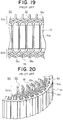
- Figure 19 is a partial front elevation of a conventional stator mounted in an automotive alternator viewed from an inner circumferential side, and Figure 20 is a perspective of part of the conventional stator mounted in an automotive alternator viewed from a front side.
- In Figures 19 and 20, a
stator 50 includes: acylindrical stator core 51 formed with a number ofslots 51a extending axially at a predetermined pitch in a circumferential direction; a stator winding 52 wound onto thestator core 51; andinsulators 53 installed in each of theslots 51a for electrically insulating the stator winding 52 from thestator core 51. Although not shown, in this conventional example a rotor has 12 poles, and thestator 50 has thirty-sixslots 51a, which is one slot per pole per phase. - The stator winding 52 is constructed by connecting in series a number of
coil segments 55 composed of short lengths of insulated electrical conductor. Each of thecoil segments 55 is formed in a general U shape consisting of a pair ofleg portions 55a joined by aturn portion 55b. - The
coil segments 55 are inserted two at time from a rear end of the stator core into sets ofslots 51a three slots apart. At that time, fourleg portions 55a are housed in eachslot 51a so as to line up in a row in a radial direction. Each of thecoil segments 55 on the inner circumferential side is inserted into a first position from the inner circumferential side of afirst slot 51a and a second position from the inner circumferential side of asecond slot 51a three slots away, and each of thecoil segments 55 on the outer circumferential side is inserted into a third position from the inner circumferential side of thefirst slot 51a and a fourth position from the inner circumferential side of thesecond slot 51a three slots away. In other words, thecoil segments 55 are housed in sets ofslots 51a three slots apart so as to be in different layers. - Next, each of the
coil segments 55 is bent such thatfree ends 55c extending outwards from a front end open outwards in a circumferential direction. Then,free ends 55c ofcoil segments 55 extending outwards from the front end from the first position from the inner circumferential side of theslots 51a are stacked in a radial direction with thefree ends 55c ofcoil segments 55 extending outwards from the front end from the second position from the inner circumferential side ofslots 51a three slots away, and are joined by soldering or laser welding. Two inner circumferential coils consisting of sixcoil segments 55 connected in series are thus obtained. - Similarly,
free ends 55c ofcoil segments 55 extending outwards from the front end from the third position from the inner circumferential side of theslots 51a are stacked in the radial direction with thefree ends 55c ofcoil segments 55 extending outwards from the front end from the fourth position from the inner circumferential side ofslots 51a three slots away, and are joined by soldering or laser welding. Two outer circumferential coils consisting of sixcoil segments 55 connected in series are thus obtained. - These inner and outer circumferential coils are connected in series to form one phase of coil having 4 turns.
- Furthermore, two other phases of coil are also formed in a similar manner.
- The stator winding 52 is formed by connecting these three phases of coil into an alternating-current connection.
- As shown in Figures 19 and 20, in the
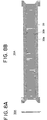
stator 50 constructed in this manner, the coil ends formed by joining thefree ends 55c of thecoil segments 55 to each other are mutually spaced and arranged in neat rows in a circumferential direction and constitute front-endcoil end groups 52a. The coil ends consisting of theturn portions 55b of thecoil segments 55 are mutually spaced and arranged in neat rows in a circumferential direction and constitute rear-endcoil end groups 52b. - In the
conventional stator 50, because the front- and rear-endcoil end groups slots 5 la three slots apart, axial heights of the front- and rear-endcoil end groups coil end groups - Thus, when this
stator 50 is mounted in an alternator, the disadvantages described below arise, and a problem has been that improvements in reliability, increases in performance, and reductions in cost have not been possible. - Namely, there is a risk that foreign matter will infiltrate the
coil end groups - Furthermore, the longer the axial length of the
coil end groups coil end groups - Also, the longer the axial length of the
coil end groups - Because there are circumferential irregularities on the inner circumferential side of the
coil end groups coil end groups - In addition, the amount of copper constituting the material of the stator winding 52 is increased, causing cost increases.
- Moreover, the greater the number of sots per pole per phase, the greater the axial length of the coil end groups, exacerbating the above disadvantages.
- In order to solve the above problems, an object of the present invention is to provide an alternator applicable for automotive use enabling the realization of improved reliability, high performance, and low cost by constructing the coil end groups such that coil ends are arranged in close proximity to one another.
- In order to achieve the above object, according to one aspect of the present invention, there is provided an alternator including:
- a rotor for forming north-seeking (N) and south-seeking (S) poles along a rotational circumference;
- a stator having a cylindrical stator core formed with a number of slots extending axially at a predetermined pitch in a circumferential direction and disposed around an outer circumference of the rotor facing the rotor and a stator winding wound onto the stator core;
- a bracket supporting the rotor and the stator;
- a rectifier disposed at one end of the rotor; and
- a cooling means operating together with rotation of the rotor for forming a passage of cooling air within the bracket for cooling the rotor and the rectifier, the stator winding comprising:
- a number of stator winding sub-portions each of which is constituted by insulated strands of wire wound onto the stator core so as to be housed in different layers relative to a slot depth direction within slots a predetermined number of slots apart, the different layers within the slots the predetermined number of slots apart being joined in series outside the slots to constitute coil ends,
- wherein each of the coil ends is formed into a connection pattern comprising a pair of root portions extending outwards from the slots the predetermined number of slots apart, a pair of inclined portions bent over and extending circumferentially from the root portions and a connecting portion connecting ends of the pair of inclined portions to each other,
- wherein coil end groups of the stator winding are constructed by arranging the coil ends formed into the connection pattern neatly into rows circumferentially at both axial ends of the stator core, and
- wherein the coil ends in at least one of the coil end groups are arranged in rows circumferentially such that the inclined portions of adjacent coil ends are in close proximity to each other without gaps.
-
-
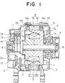
- Figure 1 is a cross section showing a construction of an automotive
alternator according to
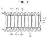
Embodiment 1 of the present invention; - Figure 2 is a partial front elevation of a stator for the automotive
alternator according to
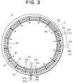
Embodiment 1 of the present invention viewed from an inner circumferential side; - Figure 3 is an end elevation explaining connections in one phase of a
stator winding in the automotive alternator according to
Embodiment 1 of the present invention; - Figure 4 is a circuit diagram for the automotive alternator according
to
Embodiment 1 of the present invention; - Figure 5 is a perspective showing a laminated core constituting a
stator core used in the automotive alternator according to
Embodiment 1 of the present invention; - Figure 6 is a diagram explaining the manufacturing process for
winding groups constituting the stator winding used in the automotive
alternator according to
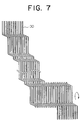
Embodiment 1 of the present invention; - Figure 7 is a diagram explaining the manufacturing process for
winding groups constituting the stator winding used in the automotive
alternator according to
Embodiment 1 of the present invention; - Figures 8A and 8B are diagrams showing an inner-layer-side
winding assembly constituting the stator winding used in the automotive
alternator according to
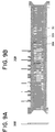
Embodiment 1 of the present invention; - Figures 9A and 9B are diagrams showing an outer-layer-side
winding assembly constituting the stator winding used in the automotive
alternator according to
Embodiment 1 of the present invention; - Figure 10 is a perspective showing part of a strand of wire
constituting the stator winding used in the automotive alternator according
to
Embodiment 1 of the present invention; - Figure 11 is a diagram explaining the arrangement of strands of
wire constituting the stator winding used in the automotive alternator
according to
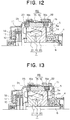
Embodiment 1 of the present invention; - Figure 12 is a partial cross section showing a construction of an
automotive alternator according to
Embodiment 4 of the present invention; - Figure 13 is a partial cross section showing a construction of an
automotive alternator according to
Embodiment 5 of the present invention; - Figure 14 is a perspective showing a stator for an automotive
alternator according to
Embodiment 6 of the present invention; - Figure 15 is a partial front elevation of a stator for the automotive
alternator according to
Embodiment 7 of the present invention viewed from an inner circumferential side; - Figures 16A to 16D are diagrams explaining the method of winding
the stator winding used in the automotive alternator according to
Embodiment 7 of the present invention; - Figure 17 is a partial front elevation of a stator for the automotive
alternator according to
Embodiment 8 of the present invention viewed from an inner circumferential side; - Figure 18 is a partial front elevation of a stator for the automotive
alternator according to
Embodiment 9 of the present invention viewed from an inner circumferential side; - Figure 19 is a partial front elevation of a conventional stator for an automotive alternator viewed from an inner circumferential side; and
- Figure 20 is a perspective of part of the conventional stator mounted in an automotive alternator viewed from a front end.
-
- The preferred embodiments of the present invention will now be explained with reference to the diagrams.
- Figure 1 is a cross section showing a construction of an automotive alternator according to
Embodiment 1 of the present invention, Figure 2 is a partial front elevation of part of a stator for this automotive alternator, Figure 3 is an end elevation explaining connections in one phase of a stator winding in this automotive alternator, Figure 4 is a circuit diagram for this automotive alternator, Figure 5 is a perspective showing a laminated core constituting a stator core in this automotive alternator, and Figures 6 and 7 are diagrams explaining the manufacturing process for winding groups constituting the stator winding used in this automotive alternator. Figures 8A and 8B are diagrams showing an inner-layer-side winding assembly constituting the stator winding used in this automotive alternator, Figure 8A being a side elevation and Figure 8B being a front elevation. Figures 9A and 9B are diagrams showing an outer-layer-side winding assembly constituting the stator winding used in this automotive alternator, Figure 9A being a side elevation and Figure 9B being a front elevation. Figure 10 is a perspective showing part of a strand of wire constituting the stator winding used in this automotive alternator, and Figure 11 is a diagram explaining the arrangement of strands of wire constituting the stator winding used in this automotive alternator. - In Figures 1 and 2, the automotive alternator is constructed by rotatably mounting a Lundell-
type rotor 7 inside a case constructed from analuminum front bracket 1 and analuminum rear bracket 2 by means of ashaft 6, and fastening astator 8 to an inner wall of the case so as to cover an outer circumferential side of therotor 7. - The
shaft 6 is rotatably supported in thefront bracket 1 and therear bracket 2. Apulley 4 is fastened to a first end of thisshaft 6 so that rotational torque from an engine can be transmitted to theshaft 6 by means of a belt (not shown). Slip rings 9 for supplying electric current to therotor 7 are fastened to a second end of theshaft 6, and a pair ofbrushes 10 are housed in abrush holder 11 disposed inside the case such that the pair of brushes slide in contact with the slip rings 9. Aregulator 18 for regulating the output voltage of thestator 8 is fastened by adhesive to aheat sink 17 fitted onto thebrush holder 11.Rectifiers 12 which are electrically connected to thestator 8 and rectify alternating current generated in thestator 8 into direct current are mounted inside thecase 3. - The
rotor 7 is a claw-pole-type rotor, and is composed of arotor coil 13 for generating magnetic flux on passage of electric current, and a pair ofpole cores rotor coil 13, magnetic poles being formed in thepole cores rotor coil 13. The pair ofpole cores magnetic poles pole cores shaft 6 facing each other such that the claw-shapedmagnetic poles fans 5 including a number ofblades 5a are fastened to first and second axial ends of therotor 7 and function as a cooling means. - The
stator 8 includes: acylindrical stator core 15 formed with a number ofslots 15a extending axially at a predetermined pitch in a circumferential direction; a stator winding 16 wound onto thestator core 15; and insulators (not shown) installed in each of theslots 15a for electrically insulating the stator winding 16 from thestator core 15. - The stator winding 16 includes a number of winding sub-portions which are wave-wound into every sixth slot of the
slots 15a such thatwires 30 alternately occupy an inner layer and an outer layer in a slot depth direction. The coil ends of thewires 30 outside the slots connecting inner layers infirst slots 15a to outer layers insecond slots 15a six slots away are formed into a connection pattern consisting of pairs ofroot portions 100a (100b) extending outwards from end surfaces of thestator core 15 from each of theslots 15a, pairs ofinclined portions 101a (101b) bent in directions approaching each other so as to extend in a circumferential direction, and connectingportions 102a (102b) connecting end portions of pairs ofinclined portions 101a (101b). At first and second axial ends of thestator core 15, coil ends formed into these connections patterns are repeated circumferentially to constitutecoil end groups inclined portions 101a (101b) of the coil ends are in close proximity to each other. - In this case, the
stator core 15 is formed with ninety-sixslots 15a at even pitch so as to house two sets of three-phase alternating-current winding portions such that the number of slots housing each phase of the winding portions corresponds to the number of magnetic poles (sixteen) in therotor 7. Furthermore, the axial length of thestator 8 is formed shorter than the axial length of the rotor core. Thecoil end groups wires 30. - Air intake openings la and 2a are disposed in axial end surfaces of the
front bracket 1 and therear bracket 2, andair discharge openings front bracket 1 and therear bracket 2, opposite the radial outside of the front-end and rear-end coil ends 16a and 16b of the stator winding 16. - Next, the winding construction of one phase of a
stator winding group 161 will be explained in detail with reference to Figure 3. Figure 3 is a rear-end elevation explaining connections in one phase of the stator winding 16, rear-end connections in the figure being indicated by solid lines and front-end connections being indicated by dotted lines. - One phase of the
stator winding group 161 is composed of first to fourth windingsub-portions 31 to 34 each formed from one strand ofwire 30. The first windingsub-portion 31 is formed by wave winding one strand ofwire 30 into every sixth slot fromslot numbers 1 to 91 so as to alternately occupy a first position from an inner circumferential side and a second position from the inner circumferential side inside theslots 15a. The second windingsub-portion 32 is formed by wave winding a strand ofwire 30 into every sixth slot fromslot numbers 1 to 91 so as to alternately occupy the second position and the first position inside theslots 15a. The third windingsub-portion 33 is formed by wave winding a strand ofwire 30 into every sixth slot fromslot numbers 1 to 91 so as to alternately occupy a third position from the inner circumferential side and a fourth position from the inner circumferential side inside theslots 15a. The fourth windingsub-portion 32 is formed by wave winding a strand ofwire 30 into every sixth slot fromslot numbers 1 to 91 so as to alternately occupy the fourth position and the third position inside theslots 15a. The strands ofwire 30 are arranged to line up in a row of four strands within eachslot 15a with the longitudinal direction of their rectangular cross sections aligned in a radial direction. - At the front end of the
stator core 15, afirst end portion 31a of the first windingsub-portion 31 extending outwards fromslot number 1 and asecond end portion 33b of the third windingsub-portion 33 extending outwards fromslot number 91 are joined, and in addition, afirst end portion 33a of the third windingsub-portion 33 extending outwards fromslot number 1 and asecond end portion 31b of the first windingsub-portion 31 extending outwards fromslot number 91 are joined to form two turns of winding. - At the rear end of the
stator core 15, afirst end portion 32a of the second windingsub-portion 32 extending outwards fromslot number 1 and asecond end portion 34b of the fourth windingsub-portion 34 extending outwards fromslot number 91 are joined, and in addition, afirst end portion 34a of the fourth windingsub-portion 34 extending outwards fromslot number 1 and asecond end portion 32b of the second windingsub-portion 32 extending outwards fromslot number 91 are joined to form two turns of winding. - In addition, a portion of the
wire 30 of the third windingsub-portion 33 extending outwards at the rear end of thestator core 15 fromslot numbers wire 30 of the fourth windingsub-portion 34 extending outwards at the rear end of thestator core 15 fromslot numbers first cut end 33c of the third windingsub-portion 33 and afirst cut end 34c of the fourth windingsub-portion 34 are joined to form one phase of thestator winding group 161 having four turns constructed by connecting the first to fourth windingsub-portions 31 to 34 in series. - Moreover, the joint portion between the
first cut end 33c of the third windingsub-portion 33 and thefirst cut end 34c of the fourth windingsub-portion 34 becomes a bridging connection connecting portion, asecond cut end 33d of the third windingsub-portion 33 and asecond cut end 34d of the fourth windingsub-portion 34 become a neutral-point lead wire (N) and a lead wire (O), respectively. - Six phases of the
stator winding group 161 are similarly formed by offsetting theslots 15a into which the strands ofwire 30 are wound one slot at a time. Then, three phases of thestator winding group 161 are formed into a star connection by connecting their respective neutral-point lead wires (N) to form a three-phase alternating-current winding 160. The remaining three phases of thestator winding group 161 are similarly connected to form a three-phase alternating-current winding 160. A stator winding 16 composed of two sets of three-phase alternating-current windings 160 is thus obtained. As shown in Figure 4, each of the three-phase alternating-current windings 160 is connected to itsown rectifier 12, and therectifiers 12 are connected in parallel so that the direct-current output from each is combined. - Next, the method of manufacturing the
stator 8 will be explained with reference to Figures 5 to 11. - First, a parallelepiped
laminated core 37 is prepared as shown in Figure 5 by laminating a predetermined number of sheets of SPCC material, which is a magnetic material, formed with ninety-sixtrapezoidal slots 37a at a predetermined pitch (an electrical angle of 30 degrees) and laser welding an outer portion thereof. - As shown in Figure 6, twelve long strands of
wire 30 are simultaneously bent in the same plane to form them into a lightning-bolt shape. Then, a windingassembly 35A, shown in Figures 8A and 8B, is prepared by progressively folding the strands of wire at right angles, as indicated by the arrow in Figure 7, using a jig. In addition, a windingassembly 35B including bridging connection portions, neutral-point lead wires, and lead wires extending outwards from a side portion, as shown in Figures 9A and 9B, is prepared in a similar manner. - Moreover, as shown in Figure 10, each strand of
wire 30 is formed by bending it into a planar pattern in whichstraight portions 30b connected byturn portions 30a are lined up at a slot pitch of six (6P). Adjacentstraight portions 30b are offset by a width dimension (W) of the strands ofwire 30 by means of theturn portions 30a. The windingassemblies wire 30 formed in the above pattern which are offset by a pitch of six slots and arranged such thatstraight portions 30b overlap as shown in Figure 11. Six end portions of the strands ofwire 30 each extend outwards from first and second sides at first and second ends of the windingassemblies turn portions 30a are arranged such that adjacent inclined portions are in close proximity to each other and line up in rows in first and second side portions of the windingassemblies - Although not shown, insulators are mounted in the
slots 37a of thelaminated core 37, and the straight portions of the two windingassemblies laminated core 37 is rolled up and its ends abutted and welded to each other to obtain thecylindrical stator core 15. By rolling up thelaminated core 37, theslots 37a (corresponding to theslots 15a in the stator core) take on a generally rectangular cross-sectional shape, and openingportions 37b of theslots 37a (corresponding to openingportions 15b of theslots 15a) become smaller than the dimensions of thestraight portions 30b in the slot-width direction. - Then, based on the connection methods shown in Figure 3, the end portions of each of the strands of
wire 30, the bridging connections portions, etc., are connected, and then thecoil end groups stator 8. - In the automotive alternator constructed in this manner, electric current is supplied from a battery (not shown) through the
brushes 10 and theslip rings 9 to therotor coil 13, generating magnetic flux. The claw-shapedmagnetic poles 22 of thefirst pole core 20 are magnetized to N polarities (north-seeking poles) by this magnetic flux, and the claw-shapedmagnetic poles 23 of thefirst pole core 21 are magnetized to S polarities (south-seeking poles) thereby. At the same time, rotational torque from the engine is transmitted through the belt and thepulley 4 to theshaft 6, rotating therotor 7. Thus, a rotating magnetic field is applied to the stator winding 16, generating electromotive force in the stator winding 16. This alternating electromotive force passes through therectifiers 12 and is rectified to direct current, its output is regulated by theregulator 18, and the battery is recharged. - At the rear end, external air is sucked in from the air intake openings 2a disposed opposite the heat sinks of the
rectifiers 12 and theheat sink 17 of theregulator 18, respectively, by rotation of thefans 5, flowing along the axis of theshaft 6, cooling therectifiers 12 and theregulator 18, and is then deflected centrifugally by thefans 5, cooling the rear-endcoil end group 16b of the stator winding 16 before being discharged to the outside through theair discharge openings 2b. At the same time, at the front end, external air is sucked in axially from the air intake openings la by rotation of thefans 5, and is then deflected centrifugally by thefans 5, cooling the front-endcoil end group 16a of the stator winding 16 before being discharged to the outside through theair discharge openings 1b. - Because, according to
Embodiment 1, the front- and rear-endcoil end groups slots 15a six slots apart such that adjacent inclined portions lOla and lOlb are in close proximity to each other, the axial length of thecoil end groups coil end groups - When this
stator 8 is mounted in an alternator, foreign matter is less likely to enter thecoil end groups 16a and 1Gb through gaps between the coil ends, and damage to the insulation on the strands ofwire 30 is suppressed. Thus, insulation quality is improved, enabling reliability to be improved. - Because the axial length of the
coil end groups 16a and 1Gb is reduced, wind resistance against the cooling ventilation flowing around thecoil end groups 16a and 1Gb is reduced, raising cooling quality, enabling temperature increases in the stator winding 16 to be suppressed. - Because the axial length of the
coil end groups 16a and 1Gb is reduced, coil resistance and coil end leakage reactance are reduced, enabling output to be improved, and copper loss is reduced, enabling efficiency to be increased. - Because circumferential irregularities occurring on the inner circumferential side of the
coil end groups 16a and 1Gb are reduced, interference noise between the coil end groups 1Ga and 1Gb and therotor 7 is reduced, decreasing wind noise. - In addition, the amount of copper, which is the material the stator winding 16 is made of, is reduced, enabling costs to be lowered.
- Because the
fans 5 are used as the cooling means, thestator 8 can be cooled inexpensively and reliably. - Because the
fans 5 are fastened to end surfaces of thepole cores coil end groups 16a and 1Gb to be effectively cooled. - Because the
coil end groups fans 5 on a downstream side of the direction of flow of the cooling air, the cooling air is efficiently supplied to thecoil end groups - Because the
air discharge openings brackets coil end groups coil end groups air discharge openings brackets - Because the coil end groups 1Ga and 1Gb are formed so as to have equal axial length, wind resistance in both ends of the
stator core 15 is generally equal and heat from the stator winding 16 is radiated from the coil end groups 1Ga and 1Gb in a balanced manner, enabling the cooling characteristics of thestator 8 to be improved. - Because the axial length of the
stator 8 is formed shorter than the axial length of the rotor core, wind resistance is reduced, improving cooling characteristics and enabling the alternator to be made more compact. - Because the
coil end groups 16a and 1Gb are formed by repeatingturn portions 30a of strands ofwire 30 in a circumferential direction, distances between inner circumferential surfaces of the coil end groups 1Ga and 1Gb and outer diameters of the fans are generally uniform relative to the circumferential direction, and noise generated by interference between the coil end groups 1Ga and 1Gb and theblades 5a is made more uniform, reducing wind noise. - Because the rotor core is constituted by the
pole cores magnetic poles rotor 7 is rotating, enabling cooling performance to be improved. - Because the
coil end groups 16a and 1Gb are impregnated with varnish, minute gaps between adjacent coil ends are stopped with varnish, enabling the penetration of foreign matter inside thecoil end groups 16a and 1Gb to be further prevented, and the inner circumferential surfaces of the coil end groups 1Ga and 1Gb become smooth, enabling wind noise to be further reduced. In addition, because the coil ends constituting the coil end groups 1Ga and 1Gb are fastened to each other by the varnish, damage to the insulation as a result of vibration of the coil ends is eliminated, improving the insulation characteristics, and the rigidity of thecoil end groups - Because the strands of
wire 30 are formed into a rectangular cross section, spaces between the coil ends can be easily filled, enhancing the above effects. In addition, the space factor of the strands ofwire 30 inside theslots 15a is increased, enabling improved transfer of heat from the strands ofwire 30 to thestator core 15. Furthermore, the surface area radiating heat from theturn portions 30a constituting the coil ends is increased, efficiently radiating heat generated by the stator winding 16. Here inEmbodiment 1, the strands ofwire 30 are formed into a rectangular cross section, but the cross-sectional shape of the strands ofwire 30 is not limited to a rectangular cross section and may be any generally flattened shape such as an elongated elliptical shape, etc. - The stator winding 16 includes two sets of three-phase alternating-
current windings 160, each of the three-phase alternating-current windings 160 being constructed by joining three phases ofstator winding groups 161 into an alternating-current connection. Thestator winding groups 161 are each constructed by connecting the first to fourth windingsub-portions 31 to 34 in series, each winding sub-portion being composed of a single strand ofwire 30. The first windingsub-portion 31 is constructed by wave winding a single strand ofwire 30 so as to alternately occupy the first and second positions of everysixth slot 15a. In other words, the first windingsub-portion 31 is constructed by wave winding a single strand ofwire 30 for one turn so as to alternately occupy the inner layer and the outer layer in a slot depth direction. Similarly, the second, third, and fourth windingsub-portions wire 30 for one turn each so as to alternately occupy inner and outer layers in a slot depth direction. - Thus, the
turn portions 30a of the strands ofwire 30 constituting the first and second windingsub-portions turn portions 30a to be arranged so as to be stacked in rows circumferentially. Similarly, theturn portions 30a of the strands ofwire 30 constituting the third and fourth windingsub-portions turn portions 30a to be arranged so as to be stacked in rows circumferentially on the outer circumferential side of the first and second windingsub-portions - Thus, by adopting this winding construction,
coil end groups 16a and 1Gb in which theinclined portions coil end groups coil end groups - Because the first to fourth winding
sub-portions 31 to 34 are each constituted by a single strand ofwire 30, the coil ends are prepared from theturn portions 30a of the strands ofwire 30. Thus, there are no joining portions betweenfree ends 55c of segment coils 55 in the coil ends and the heights of thecoil end groups - The winding
assembly 35A is constituted by a pair of winding groups consisting of a winding group in which six first windingsub-portions 31 are arranged in rows at a pitch of one slot and a winding group in which six second windingsub-portions 32, which are constructed by offsetting by an electrical angle of 180 degrees to the first windingsub-portions 31 and winding in an inverted manner, are arranged in rows at a pitch of one slot and the windinggroup 35B is constituted by a pair of winding groups consisting of a winding group in which six third windingsub-portions 33 are arranged in rows at a pitch of one slot and a winding group in which six fourth windingsub-portions 34, which are constructed by offsetting by an electrical angle of 180 degrees to the third windingsub-portions 33 and winding in an inverted manner, are arranged in rows at a pitch of one slot. Because these windingassemblies coil segments 55 are used, raising the productivity and reliability of the stator winding. - Four strands of
wire 30 are arranged so as to line up in a row radially within eachslot 15a, and theturn portions 30a are arranged to line up in two rows circumferentially. Thus, theturn portions 30a constituting thecoil end groups coil end groups coil end groups 16a and 1Gb is reduced, enabling wind noise resulting from the rotation of therotor 7 to be reduced, reducing coil end leakage reactance and improving output and efficiency. - The
rotor 7 has sixteen magnetic poles, and ninety-six (96)slots 15a are formed at even pitch in thestator core 15. Because the strands ofwire 30 are wave wound into everysixth slot 15a, the pitch of the slots into which the strands ofwire 30 are wound corresponds to the pitch between the north-seeking and south-seeking poles of therotor 7, making the stator winding 16 a full-node winding. Thus, maximum torque can be obtained, enabling the achievement of increased output. - Because the open dimensions of the opening
portions 15b of theslots 15a are constructed so as to be smaller than the dimensions of the strands ofwire 30 in the width direction of theslots 15a, the strands ofwire 30 are prevented from popping out of theslots 15a towards the radial inside and noise at the openingportions 15b due to interference with therotor 7 can be reduced. - As shown in Figure 4, two sets of three-phase alternating-current winding 160 are constructed by forming into two star connections three
stator winding groups 161 each constructed by connecting the first to fourth windingsub-portions 31 to 34 in series, and each of these two sets of threephase alternating-current windings 160 is connected to itsown rectifier 12, and in addition, the outputs from the tworectifiers 12 are connected in parallel. Thus, the direct current outputs of the three-phase alternating-current windings 160 which have four turns each can be combined and extracted, enabling elimination of power generation deficits in low revolution regions. - By adopting this winding construction, increases in the number of turns in the stator winding 16 can be easily adapted for by lining up the
straight portions 30b of the winding assemblies 35 (35A and 35B) which are composed of continuous strands of wire and installing them into the stator core so that they stack up on top of each other. - The
stator 8 according toEmbodiment 1 can be prepared by inserting the winding assemblies 35 which are composed of continuous strands of wire into theslots 37a in the parallelepiped laminatedcore 37 through the openingportions 37b and then rolling thelaminated core 37 into an annular shape. Thus, because the open dimensions of the openingportions 37b of theslots 37a can be made larger than the dimensions of the strands ofwire 30 in the width direction of the slots, the operation of inserting the windingassemblies portions 37b of thelaminated core 37 can be made smaller than the dimensions of the strands ofwire 30 in the width direction of the slots when thelaminated core 37 is rolled up, the space factor is increased, enabling output to be improved. In addition, even if the number of slots is increased, the productivity of the stator will not deteriorate. - The number of slots housing the stator winding 16 is two per pole per phase, and there are two three-phase alternating-
current windings 160 each corresponding to the number of slots per pole per phase. Thus, the magnetomotive wave form can be made to approximate a sinusoidal wave, reducing higher harmonic wave components and ensuring stable output. Because the number ofslots 15a is increased, teeth in thestator core 15 are slender, reducing magnetic leakage through teeth straddling the facing claw-shapedmagnetic poles slots 15a means a correspondingly greater number ofturn portions 30a, the heat-radiating characteristics of the coil ends are improved. - Because the
slots 15a and the openingportions 15b are arranged to be evenly spaced at an electrical angle of 30 degrees, magnetic ripples which result in excitation forces which cause magnetic noise can be reduced. - Moreover, in
Embodiment 1,fans 5 were disposed on both axial ends of therotor 7, but thefans 5 do not have to be disposed on both ends of therotor 7, and they may be disposed in consideration of the positions of the stator winding or the rectifiers which are large heat-generating bodies. For example, the coil ends of the stator winding which are large heat generating bodies can be disposed on the discharge side of a fan with a large cooling speed, and a fan disposed on an end portion of the rotor on the side where the rectifiers are disposed. Furthermore, when mounted to an automotive engine, because the pulley is normally connected to a crankshaft by means of a belt, the fan may be disposed on the side away from the pulley so that the cooling exhaust from the fan does not affect the belt. - In
Embodiment 1 above, theair discharge openings coil end groups Embodiment 2, theair discharge openings root portions - In this case, foreign matter blown inside the
brackets air discharge openings coil end groups 16a and 1Gb through gaps betweenadjacent root portions - In
Embodiment 3, thefan 5 fastened to the rear-end surface of therotor 7 has a larger number of blades than thefan 5 fastened to the front-end surface of therotor 7. Moreover, the rest of the construction is the same as inEmbodiment 1. - In
Embodiment 3, because the number of blades of the rear-end fan 5 is greater than the number of blades of the front-end fan 5, the capacity of the rear-end fan 5 is increased. Thus, the volume of air in the rear end of therotor 7 where heat-generating parts such as therectifiers 12, theregulator 18, etc., are disposed is increased, suppressing temperature increases in these heat-generating parts. - As shown in Figure 12, in
Embodiment 4, axial lengths of thecoil end groups coil end groups fans 5 in the axial direction. Moreover, the rest of the construction is the same as inEmbodiment 1. - In a
stator 8A according toEmbodiment 4, because thefans 5 and thecoil end groups 16a and 1Gb overlap axially, cooling air is supplied directly to the coil end groups 1Ga and 1Gb by means of thefans 5, heat from the stator winding 16 is effectively dissipated by thecoil end groups - As shown in Figure 13, in
Embodiment 5, the axial length of thecoil end group 16a is formed so as to be longer than the axial length of thecoil end group 16b. Moreover, the rest of the construction is the same as inEmbodiment 1. - In a
stator 8B according toEmbodiment 4, wind resistance is lower in the rear end than in the front end, increasing the volume of air in the rear end of therotor 7 where heat-generating parts such as therectifiers 12, theregulator 18, etc., are disposed and suppressing temperature increases in these heat-generating parts. - As shown in Figure 14, in
Embodiment 6, electrically-insulative resin 25 such as epoxy resin is disposed so as to completely cover the coil end groups 1Ga and 16b. Moreover, the rest of the construction is the same as inEmbodiment 1 above. - In a
stator 8C according toEmbodiment 6, because the electrically-insulative resin 25 is disposed so as to completely cover the coil end groups 1Ga and 16b, the coil ends are fastened to each other, improving insulation characteristics by eliminating damage to the insulation due to vibration of the coil ends, and enabling the reduction of magnetic noise by increasing the rigidity of thecoil end groups - Because the
inclined portions insulative resin 25 is smooth, suppressing increases in noise due to interference with therotor 7 as a result of the provision of the electrically-insulative resin 25. - Moreover, in
Embodiment 6 above, the coil end groups 1Ga and 16b are completely covered by the electrically-insulative resin 25, but the electrically-insulative resin 25 may be disposed so as to cover at least one surface selected between the inner circumferential surface and the outer circumferential surface of thecoil end groups - In that case, because the coil ends are fastened to each other, insulation characteristics are improved, the rigidity of the coil end groups 1Ga and 1Gb is increased, enabling the reduction of magnetic noise. If the electrically-
insulative resin 25 is disposed so as to cover the inner circumferential surface of the coil end groups 1Ga and 16b, noise due to interference with therotor 7 is reduced, reducing wind noise. And if the electrically-insulative resin 25 is disposed so as to cover the outer circumferential surface of the coil end groups 1Ga and 16b, suppressing infiltration inside the coil end groups 1Ga and 16b by foreign matter blown in from outside through theair discharge openings - In
Embodiment 6 above, epoxy resin is used as the electrically-insulative resin 25, but a mixture containing a component with a higher thermal conductivity than the principal component of the resin itself may be used as the electrically-insulative resin. For example, the electrically-insulative resin 25 may be a mixture of epoxy resin (principal component) having a thermal conductivity of 0.5 (W/mk) and alumina having a thermal conductivity of 3.5 (W/mk) in a ratio of one to four (1: 4). In that case, because heat generated in the stator winding 16 is quickly conducted through the electrically-insulative resin to the surface of the electrically-insulative resin and radiated from the surface of the electrically-insulative resin, cooling of the stator winding 16 is improved. - Figure 15 is a partial front elevation of a stator for the automotive alternator according to
Embodiment 7 of the present invention viewed from an inner circumferential side. - In Figure 15, a
stator 80 includes: acylindrical stator core 15 formed with a number ofslots 15a extending axially at a predetermined pitch in a circumferential direction; a stator winding 40 wound onto thestator core 15; and insulators (not shown) installed in each of theslots 15a for electrically insulating the stator winding 40 from thestator core 15. The stator winding 40 is constructed by connecting in series a number ofcoil segments 41 composed of short lengths of insulated electrical conductor of copper material or the like having a rectangular cross section. Each of thecoil segments 41 is formed in a general U shape consisting of a pair ofleg portions 41a joined by aturn portion 41b. - The stator winding 40 includes a number of winding sub-portions in which
coil segments 41 are inserted into everysixth slot 15a so as to alternately occupy an inner layer and an outer layer in a slot depth direction, andfree ends 41c extending outwards from the inner layer offirst slots 15a andfree ends 41c extending outwards from the outer layer ofsecond slots 15a six slots away are joined to each other outside the slots. The coil ends outside the slots connecting inner layers infirst slots 15a to outer layers insecond slots 15a six slots away are formed into a connection pattern consisting of pairs ofroot portions 100a (100b) extending outwards from end surfaces of thestator core 15 from each of theslots 15a, pairs ofinclined portions 101a (101b) bent in directions approaching each other so as to extend in a circumferential direction, and connectingportions 102a (102b) connecting end portions of pairs ofinclinedportions 101a (101b). At first and second axial ends of thestator core 15, coil ends formed into these connections patterns are repeated circumferentially to constitutecoil end groups - Moreover, the rest of the construction is the same as in
Embodiment 1 above. - Next, the winding method for one phase of stator winding group will be explained with reference to Figures 16A to 16D.
- The
coil segments 41 are inserted two at time from the rear end of thecylindrical stator core 15 into sets ofslots 15a six slots apart, as shown in Figure 1GA. Each of thecoil segments 41 on the inner circumferential side is inserted into the first position of afirst slot 15a and the second position of asecond slot 15a six slots away, and each of thecoil segments 41 on the outer circumferential side is inserted into the third position of thefirst slot 15a and the fourth position of thesecond slot 15a six slots away. Thus, fourleg portions 41a are housed in eachslot 15a so as to line up in a row in a radial direction. Thecoil segments 41 are housed in sets ofslots 15a six slots apart so as to be in different layers. - Next, each of the
coil segments 41 is bent such that free ends 41c extending outwards from the front end open outwards in a circumferential direction. Here, Figure 16B shows the free ends of one strand ofcoil segment 41 bent outwards in a circumferential direction. - Then, free ends 41c of
coil segments 41 extending outwards at the front end from the first positions of theslots 15a are stacked in a radial direction with the free ends 41c ofcoil segments 41 extending outwards at the front end from the second positions ofslots 15a six slots away, and are joined by soldering or laser welding, as shown in Figure 16C. Two inner circumferential coils consisting of innercircumferential coil segments 41 connected in series are thus obtained. Moreover, in order to distinguish thecoil segments 41 on the inner circumferential side from those on the outer circumferential side, the free ends of the outercircumferential coil segments 41 are shown in an unbent state in Figure 1GC. - Similarly, free ends 41c of
coil segments 41 extending outwards at the front end from the third positions of theslots 15a are stacked in a radial direction with the free ends 41c ofcoil segments 41 extending outwards at the front end from the fourth positions ofslots 15a six slots away, and are joined by soldering or laser welding, as shown in Figure 16D. Two outer circumferential coils consisting of outercircumferential coil segments 41 connected in series are thus obtained. - These inner and outer circumferential coils are connected based on the connections shown in Figure 3 to form one phase of stator winding group having 4 turns.
- Five more phases of stator winding groups are constructed by offsetting the groups of
coil segments 41 by one slot each and connecting them similarly. - Three phases each of these stator winding groups are connected into alternating-current connections to form two sets of three-phase alternating-current windings constituting the stator winding 40.
- In the
stator 80 constructed in the above manner, coil ends constituted by theturn portions 41b of thecoil segments 41 at the first end of thestator core 15 are repeated circumferentially to formcoil end group 40b, and coil ends constituted by the joint portions betweenfree ends 41c of thecoil segments 41 at the second end of thestator core 15 are repeated circumferentially to formcoil end group 40a. In bothcoil end groups inclined portions 101a (101b) of adjacent coil ends are in close proximity with each other. Consequently, because the axial length of thecoil end groups coil end groups coil end groups Embodiment 1 can also be achieved inEmbodiment 7. - Furthermore, because the
short coil segments 41 are used, the coil end shape can be formed uniformly, enabling a stator winding 40 havingcoil end groups portions - All of the
coil segments 41 are inserted into theslots 15a from the rear end of thestator core 15. Thus, because the rear-endcoil end group 40b is constituted only by theturn portions 41b, each of the coil ends in thecoil end group 40b have the same shape, providing superior alignment. Similarly, because the front-endcoil end group 40a is constituted only by the joint portions betweenfree ends 41c, each of the coil ends in thecoil end group 40a have the same shape, providing superior alignment. - Moreover, in
Embodiment 7, becausecoil segments 41 formed with a general U shape are used for the strands of wire, an operation is required for joining the free ends 41c to each other and the axial length of thecoil end group 40a is made proportionately longer by the presence of the joint portions between the free ends 41c compared toEmbodiment 1 in which strands ofwire 30 composed of continuous wire is used, butEmbodiment 7 is superior from the standpoint of alignment of the coil ends and installation of the coils in theslots 15a. - As shown in Figure 17, in
Embodiment 8, the coil ends constituted by theturn portions 41b of thecoil segments 41 are repeated circumferentially to formcoil end group 40b with theinclined portions 101b of adjacent coil ends in close proximity to each other, and the coil ends constituted by the joint portions between the free ends 41c of thecoil segments 41 are spaced from each other and repeated circumferentially to formcoil end group 40a. - Moreover, the rest of the construction is the same as in
Embodiment 7 above. - In a
stator 80A constructed in this manner, the axial length of thecoil end group 40b constituted by theturn portions 41b of thecoil segments 41 is shorter than the axial length of the conventionalcoil end group 52b and circumferential irregularities on the inner circumferential side can be significantly reduced. - Moreover, because the axial length of the
coil end group 40b is shorter than the axial length of thecoil end group 40a, it is desirable for thestator 80A to be mounted in the alternator with thecoil end group 40b positioned at the rear end if consideration is to be given to the cooling of therectifiers 12 and theregulator 18. - As shown in Figure 18, in
Embodiment 9, the coil ends constituted by the joint portions between the free ends 41c of thecoil segments 41 are repeated circumferentially to formcoil end group 40a with theinclined portions 101b of adjacent coil ends in close proximity to each other, and the coil ends constituted by theturn portions 41b of thecoil segments 41 are spaced from each other and repeated circumferentially to formcoil end group 40b. - Moreover, the rest of the construction is the same as in
Embodiment 7 above. - In a
stator 80B constructed in this manner, the axial length of thecoil end group 40a constituted by the joint portions between the free ends 41c of thecoil segments 41 is shorter than the axial length of the conventionalcoil end group 52b and circumferential irregularities on the inner circumferential side can be significantly reduced. - Moreover, because the axial length of the
coil end group 40a is shorter than the axial length of thecoil end group 40b, it is desirable for thestator 80B to be mounted in the alternator with thecoil end group 40a positioned at the rear end if consideration is to be given to the cooling of therectifiers 12 and theregulator 18. - Moreover, in each of the above embodiments, the
inclined portions inclined portions portions - Furthermore, the present invention is not limited to a stator winding having the winding constructions shown in the above embodiments, and may have any winding construction in which electrical conductors are housed in different layers in the slot depth direction in slots a predetermined number of slots apart, coil ends connect the electrical conductors outside the slots, and the coil ends are repeated so as to be arranged neatly in rows in the circumferential direction.
- In each of the above embodiments, the
fans 5 are disposed inside thecase 3, but a fan may also be disposed outside the automotive alternator so as to rotate together with the rotation of the rotor. - Each of the above embodiments has been explained for
stator winding groups 161 in which each phase has 4 turns, but the number of turns in the phases of thestator winding groups 161 should not be limited to four turns. When even lower-speed output is required, each phase of the stator winding groups may be made with six turns or eight turns. - Each of the above embodiments has been explained for use in an alternator with full-node windings, but the present constructions may also be used in an alternator with short-node windings (i.e., not full-node windings).
- The present invention can also be applied to automotive alternators of the type in which the rotor coil is secured to a bracket and a rotating magnetic field is supplied across an air gap.
- In each of the above embodiments, the number of slots in the stator was ninety-six slots for sixteen magnetic poles, but three phases and seventy-two slots for twelve magnetic poles, three phases and 120 slots for twenty poles, etc., may also be adopted. Furthermore, in the case of one slot per pole per phase, there may also be forty-eight slots for sixteen poles, thirty-six slots for twelve poles, sixty slots for twenty poles, etc. Moreover, because a larger number of slots per pole per phase makes the slot pitch becomes narrower, it becomes easier to place the
inclined portions - Each of the above embodiments used a Lundell-type rotor having claw-shaped magnetic poles, but the same effects can be achieved using a Salent-type rotor having projecting magnetic poles.
- In each of the above embodiments, the rectifiers are disposed at the end of the rotor away from the pulley and the fan is disposed at the same end, but the fan may also be disposed at the end near the rectifiers. When there is no particular problem with the temperature of the rectifiers, the fan may also be disposed at the end away from the pulley. Because the height of the coil ends of the stator is low, wind resistance on the discharge side in the wind channel of the fan is significantly reduced, increasing the overall amount of cooling air. Consequently, suitable relative positions for the rectifiers and the fans or for the pulley and the fans may also be selected in consideration of the position where the alternator is mounted on the engine, of wind noise, of magnetic noise, and of the temperature conditions of each portion.
- In
Embodiment 1 above, the insulators are inserted on the laminated core side before the insertion of the winding assemblies into the laminated core, but the insulators may also first be wrapped around the portions of the winding assemblies to be housed in the slots and inserted into the laminated core together with the winding assemblies. Furthermore, a long strip of insulators may be placed on top of the parallelepiped laminated core and the winding assemblies inserted form above such that the insulators are simultaneously inserted into and housed inside the slots together with the wire-strand groups. In that case, at a later stage, the protruding insulators may be removed together in one step. In addition, the portions of the winding assemblies to be housed in the slots may be pre-molded with insulating resin. In that case, mass-producibility is significantly improved. - The present invention is constructed in the above manner and exhibits the effects described below.
- According to the present invention, there is provided an alternator including:
- a rotor for forming north-seeking (N) and south-seeking (S) poles along a rotational circumference;
- a stator having a cylindrical stator core formed with a number of slots extending axially at a predetermined pitch in a circumferential direction and disposed around an outer circumference of the rotor facing the rotor and a stator winding wound onto the stator core;
- a bracket supporting the rotor and the stator;
- a rectifier disposed at one end of the rotor; and
- a cooling means operating together with rotation of the rotor for forming a passage of cooling air within the bracket for cooling the rotor and the rectifier, the stator winding comprising:
- a number of stator winding sub-portions each of which is constituted by insulated strands of wire wound onto the stator core so as to be housed in different layers relative to a slot depth direction within slots a predetermined number of slots apart, the different layers within the slots the predetermined number of slots apart being joined in series outside the slots to constitute coil ends,
- wherein each of the coil ends is formed into a connection pattern comprising a pair of root portions extending outwards from the slots the predetermined number of slots apart, a pair of inclined portions bent over and extending circumferentially from the root portions and a connecting portion connecting ends of the pair of inclined portions to each other,
- wherein coil end groups of the stator winding are constructed by arranging the coil ends formed into the connection pattern neatly into rows circumferentially at both axial ends of the stator core, and
- wherein the coil ends in at least one of the coil end groups are arranged in rows circumferentially such that the inclined portions of adjacent coil ends are in close proximity to each other without gaps. Thus, because axial length of the coil end groups is reduced and circumferential irregularities arising on the inner circumferential side of the coil end groups are also reduced, an alternator is provided which enables the realization of improved reliability, high performance, and low cost.
-
- Because at least one of the coil end groups of the stator winding may be disposed in a vicinity of the cooling means on a downstream side of the cooling means in the passage, cooling of the coil end groups is improved, suppressing temperature increases in the stator winding.
- Because the bracket may be provided with a number of openings radially outside at least one of the coil end groups, cooling ventilation in which the temperature has risen due to the cooling of the coil end groups is quickly expelled to the exterior. Thus, poor cooling of the stator winding as a result of heated cooling ventilation remaining inside the bracket is ameliorated.
- Because the cooling means may be a fan disposed on at least one end portion of the rotor, the fan being rotated together with the rotor, cooling ventilation is supplied to the coil end groups from radially inside, increasing the cooling effect and enabling the cooling means to be constructed inexpensively.
- Because distances between inner circumferential surfaces of the coil end groups and an outer diameter of the fan may be substantially uniform in a circumferential direction, noise due to interference between the blades and inner circumferential surfaces of the coil end groups is made uniform in the circumferential direction, reducing wind noise.
- Because the axial length of the stator may be shorter than the axial length of the rotor, wind resistance is reduced, improving cooling and enabling the size of the alternator to be reduced.
- Because the axial lengths of the coil end groups may be equal at first and second axial ends of the stator core, wind resistance becomes generally the same at both axial ends of the stator core, enabling the stator to be uniformly cooled.
- Because the axial length of the coil end groups at the first axial end of the stator core may be shorter than an axial length of the coil end groups at the second axial end of the stator core, wind resistance is reduced at the first end of the stator, enabling temperature increases in the rectifiers to be suppressed.
- Because the rotor may be a claw pole type, the rotor functions as a wind conveying means, improving cooling.
- Because the number of slots may be two or more per pole per phase, the axial length of the coil end groups can be further reduced.
- Because electrically-insulative resin may be disposed so as to cover at least one side of at least one of the coil end groups, the side being selected from an inner circumferential side and an outer circumferential side, gaps between the inclined portions of the coil ends are filled, suppressing the infiltration of foreign matter into the coil end groups, increasing the rigidity of the stator, and reducing electromagnetic noise.
- Because the cross-sectional shape of the strands of wire may be a generally flat shape, the distance between the coil ends can be further compacted.
- Because the strands of wire may be coil segments composed of short lengths of insulated electrical conductor, it becomes easier to form the coil end shape uniformly, and easier to place the inclined portions in close proximity.
- Because the coil segments may be insulated electrical conductors formed into a general U shape, and each of the winding sub-portions may be constructed by inserting the coil segments so as to form different layers relative to the slot depth direction within the slots the predetermined number of slots apart, bending free ends of the coil segments extending outwards from the slots the predetermined number of slots apart towards each other in a circumferential direction for connection, and joining the free ends, the inclined portions of the coil ends can easily be formed in close proximity with each other, facilitating the manufacture of the stator.
- Because the coil segments may be inserted into the slots from one axial end of the stator core such that U-shaped turn portions are arranged in rows, the coil ends constituting each of the coil end groups have the same general shape, increasing the alignment of the coil ends.
- Because the strands of wire may be continuous wires composed of insulated electrical conductors, the coil ends are constituted by continuous wire turn portions, reducing the axial length of the coil end groups.
- Because the winding sub-portions may comprise first winding sub-portions and second winding sub-portions, each of the first winding sub-portions having one turn and being constructed by winding one strand of insulated wire so as to fold back outside the slots at end surfaces of the stator core and alternately occupy an inner layer and an outer layer in the slot depth direction within the slots at intervals of the predetermined number of slots, and each of the second winding sub-portions having one turn and being constructed by winding one strand of insulated wire so as to fold back outside the slots at end surfaces of the stator core and alternately occupy an inner layer and an outer layer in the slot depth direction within the slots at intervals of the predetermined number of slots and so as to be inverted and offset from the first winding sub-portions by an electrical angle of 180° ; and the stator winding may be constructed by at least one set of winding assembly constructed by a pair of a first winding group and a second winding group, the first winding group being constructed by arranging the first winding sub-portions, whose number are the same as the predetermined number of slots, at a slot pitch of one, and the second winding group being constructed by arranging the second winding sub-portions, whose number are the same as the predetermined number of slots, at a slot pitch of one. Thus, the coil ends can be arranged in rows at high density, enabling coil end groups in which the inclined portions of the coil ends are arranged in close proximity to each other without gaps to be prepared easily, thus enabling stator windings having an increased number of turns in each phase of the winding to be easily adapted to by increasing the number of sets of winding assemblies.
Claims (10)
- An alternator comprising:a rotor (7) for forming north-seeking (N) and south-seeking (S) poles along a rotational circumference;a stator (8,8A,8B,8C,80,80A,80B) having a cylindrical stator core (15) formed with a number of slots (15a) extending axially at a predetermined pitch in a circumferential direction and disposed around an outer circumference of said rotor (7) facing said rotor and a stator winding (16,40) wound onto said stator core;a bracket (1,2) supporting said rotor and said stator;a rectifier (12) disposed at one end of said rotor; anda cooling means (5) operating together with rotation of said rotor for forming a passage of cooling air within said bracket for cooling said rotor and said rectifier, said stator winding (16,40) comprising:a number of stator winding sub-portions (31,32,33,34) each of which is constituted by insulated strands of wire (30,41) wound onto said stator core so as to be housed in different layers relative to a slot depth direction within slots a predetermined number of slots apart, said different layers within said slots said predetermined number of slots apart being joined in series outside said slots to constitute coil ends,wherein each of said coil ends is formed into a connection pattern comprising a pair of root portions (100a,100b) extending outwards from said slots said predetermined number of slots apart, a pair of inclined portions (101a,101b) bent over and extending circumferentially from said root portions and a connecting portion (102a,102b) connecting ends of said pair of inclined portions to each other,wherein coil end groups (16a,16b,40a,40b) of said stator winding (16,40) are constructed by arranging said coil ends formed into said connection pattern neatly into rows circumferentially at both axial ends of said stator core (15), andwherein said coil ends in at least one of said coil end groups (16a,16b,40a,40b) are arranged in rows circumferentially such that said inclined portions (101a,101b) of adjacent coil ends are in close proximity to each other without gaps.
- The alternator according to Claim 1, wherein at least one of said coil end groups (16a,16b,40a,40b) of said stator winding (16,40) is disposed in a vicinity of said cooling means (5) on a downstream side of said cooling means in said passage.
- The alternator according to either of Claims 1 or 2, wherein said bracket (1,2) is provided with a number of openings (lb,2b) radially outside at least one of said coil end groups (16a,16b,40a,40b).
- The alternator according to any of Claims 1 to 3, wherein an axial length of said stator (8) is shorter than an axial length of said rotor (7).
- The alternator according to any of Claims 1 to 4, wherein axial lengths of said coil end groups (16a,16b,40a,40b) are equal at first and second axial ends of said stator core (15).
- The alternator according to any of Claims 1 to 4, wherein an axial length of said coil end groups (16b,40b) at said first axial end of said stator core (15) is shorter than an axial length of said coil end groups (16a,40a) at said second axial end of said stator core.
- The alternator according to any of Claims 1 to 6, wherein said strands of wire are coil segments (41) composed of short lengths of insulated electrical conductor.
- The alternator according to Claim 7, whereinsaid coil segments (41) are insulated electrical conductors formed into a general U shape, andeach of said winding sub-portions is constructed by inserting said coil segments (41) so as to form different layers relative to said slot depth direction within said slots (15a) said predetermined number of slots apart, bending free ends (41c) of said coil segments extending outwards from said slots said predetermined number of slots apart towards each other in a circumferential direction for connection, and joining said free ends.
- The alternator according to any of Claims 1 to 6, wherein said strands of wire are continuous wires (30) composed of insulated electrical conductors.
- The alternator according to any of Claims 1 to 6,
wherein said winding sub-portions comprises first winding sub-portions (31,33) and second winding sub-portions (32,34), each of said first winding sub-portions (31,33) having one turn and being constructed by winding one strand of insulated wire (30) so as to fold back outside said slots at end surfaces of said stator core (15) and alternately occupy an inner layer and an outer layer in said slot depth direction within said slots (15a) at intervals of said predetermined number of slots, and each of said second winding sub-portions (32,34) having one turn and being constructed by winding one strand of insulated wire (30) so as to fold back outside said slots at end surfaces of said stator core (15) and alternately occupy an inner layer and an outer layer in said slot depth direction within said slots (15a) at intervals of said predetermined number of slots and so as to be inverted and offset from said first winding sub-portions (31,33) by an electrical angle of 180° ; and
wherein said stator winding (16) is constructed by at least one set of winding assembly (35A,35B) constructed by a pair of a first winding group and a second winding group, said first winding group being constructed by arranging said first winding sub-portions (31,33), whose number are the same as said predetermined number of slots, at a slot pitch of one, and said second winding group being constructed by arranging said second winding sub-portions (32,34), whose number are the same as said predetermined number of slots, at a slot pitch of one.
Applications Claiming Priority (26)
| Application Number | Priority Date | Filing Date | Title |
|---|---|---|---|
| JP35519499 | 1999-12-14 | ||
| JP35519499 | 1999-12-14 | ||
| JP35888899 | 1999-12-17 | ||
| JP35888899A JP3400760B2 (en) | 1999-12-17 | 1999-12-17 | AC generator |
| JP36128699 | 1999-12-20 | ||
| JP36128699A JP3347115B2 (en) | 1999-12-20 | 1999-12-20 | AC generator |
| JP36845399 | 1999-12-24 | ||
| JP36753499 | 1999-12-24 | ||
| JP36753499A JP3256695B2 (en) | 1999-12-24 | 1999-12-24 | Alternator stator |
| JP36845399 | 1999-12-24 | ||
| JP37716899 | 1999-12-27 | ||
| JP37716799 | 1999-12-27 | ||
| JP37025499A JP3383251B2 (en) | 1999-12-27 | 1999-12-27 | Vehicle alternator stator |
| JP37716899A JP3310967B2 (en) | 1999-12-27 | 1999-12-27 | AC generator manufacturing method |
| JP37716799 | 1999-12-27 | ||
| JP37025499 | 1999-12-27 | ||
| JP2000003621 | 2000-01-12 | ||
| JP2000003621A JP3347116B2 (en) | 2000-01-12 | 2000-01-12 | Alternator |
| JP2000011704A JP3155534B1 (en) | 2000-01-20 | 2000-01-20 | Alternator stator |
| JP2000011680A JP3264912B2 (en) | 2000-01-20 | 2000-01-20 | AC generator |
| JP2000011680 | 2000-01-20 | ||
| JP2000011704 | 2000-01-20 | ||
| JP2000015915A JP3256696B2 (en) | 2000-01-25 | 2000-01-25 | AC generator |
| JP2000017417A JP3347118B2 (en) | 2000-01-26 | 2000-01-26 | AC generator |
| JP2000017417 | 2000-01-26 | ||
| JP2000015915 | 2000-05-31 |
Publications (3)
| Publication Number | Publication Date |
|---|---|
| EP1109295A2 true EP1109295A2 (en) | 2001-06-20 |
| EP1109295A3 EP1109295A3 (en) | 2002-04-10 |
| EP1109295B1 EP1109295B1 (en) | 2005-03-02 |
Family
ID=27584368
Family Applications (1)
| Application Number | Title | Priority Date | Filing Date |
|---|---|---|---|
| EP20000126512 Expired - Lifetime EP1109295B1 (en) | 1999-12-14 | 2000-12-08 | Winding heads for the stator of an alternator |
Country Status (1)
| Country | Link |
|---|---|
| EP (1) | EP1109295B1 (en) |
Cited By (7)
| Publication number | Priority date | Publication date | Assignee | Title |
|---|---|---|---|---|
| US6707211B2 (en) | 2001-07-18 | 2004-03-16 | Mitsubishi Denki Kabushiki Kaisha | Stator for an automotive alternator and method for manufacture thereof |
| EP1416610A1 (en) * | 2002-10-08 | 2004-05-06 | Mitsubishi Denki Kabushiki Kaisha | Stator for an automotive alternator and a method for manufacture thereof |
| CN103944318A (en) * | 2014-04-25 | 2014-07-23 | 哈尔滨工业大学 | Multiphase high-speed alternating current motor system |
| CN106300716A (en) * | 2016-06-17 | 2017-01-04 | 浙江方正电机股份有限公司 | Three-phase motor stator |
| CN106416019A (en) * | 2014-04-17 | 2017-02-15 | 法雷奥电机设备公司 | Method for the production of a winding of an electric machine stator and corresponding stator |
| CN111448743A (en) * | 2017-12-20 | 2020-07-24 | 法雷奥电机设备公司 | Stator for rotating electric machine |
| US10819175B2 (en) | 2015-05-22 | 2020-10-27 | Mitsubishi Electric Corporation | Rotating electric machine and rotating electric machine manufacturing method |
Citations (7)
| Publication number | Priority date | Publication date | Assignee | Title |
|---|---|---|---|---|
| US1926331A (en) * | 1928-05-11 | 1933-09-12 | Delco Remy Corp | Electric coil |
| US3453468A (en) * | 1966-09-21 | 1969-07-01 | Kurz & Root Co Inc | Dynamoelectric machine winding arrangement with end turn insulation and method of making the same |
| US3749950A (en) * | 1972-05-23 | 1973-07-31 | Gen Electric | Dynamoelectric machine having enhanced cooling |
| JPH0438148A (en) * | 1990-05-31 | 1992-02-07 | Mitsuba Electric Mfg Co Ltd | Generator for vehicle |
| JPH10126992A (en) * | 1996-10-23 | 1998-05-15 | Nishishiba Electric Co Ltd | Random stator winding |
| JPH10336972A (en) * | 1997-05-26 | 1998-12-18 | Denso Corp | Electric rotating machine |
| JPH11155270A (en) * | 1997-05-26 | 1999-06-08 | Denso Corp | Vehicle ac generator |
-
2000
- 2000-12-08 EP EP20000126512 patent/EP1109295B1/en not_active Expired - Lifetime
Patent Citations (7)
| Publication number | Priority date | Publication date | Assignee | Title |
|---|---|---|---|---|
| US1926331A (en) * | 1928-05-11 | 1933-09-12 | Delco Remy Corp | Electric coil |
| US3453468A (en) * | 1966-09-21 | 1969-07-01 | Kurz & Root Co Inc | Dynamoelectric machine winding arrangement with end turn insulation and method of making the same |
| US3749950A (en) * | 1972-05-23 | 1973-07-31 | Gen Electric | Dynamoelectric machine having enhanced cooling |
| JPH0438148A (en) * | 1990-05-31 | 1992-02-07 | Mitsuba Electric Mfg Co Ltd | Generator for vehicle |
| JPH10126992A (en) * | 1996-10-23 | 1998-05-15 | Nishishiba Electric Co Ltd | Random stator winding |
| JPH10336972A (en) * | 1997-05-26 | 1998-12-18 | Denso Corp | Electric rotating machine |
| JPH11155270A (en) * | 1997-05-26 | 1999-06-08 | Denso Corp | Vehicle ac generator |
Non-Patent Citations (4)
| Title |
|---|
| PATENT ABSTRACTS OF JAPAN vol. 016, no. 221 (E-1205), 22 May 1992 (1992-05-22) & JP 04 038148 A (MITSUBA ELECTRIC MFG CO LTD), 7 February 1992 (1992-02-07) * |
| PATENT ABSTRACTS OF JAPAN vol. 1998, no. 10, 31 August 1998 (1998-08-31) & JP 10 126992 A (NISHISHIBA ELECTRIC CO LTD), 15 May 1998 (1998-05-15) * |
| PATENT ABSTRACTS OF JAPAN vol. 1999, no. 03, 31 March 1999 (1999-03-31) & JP 10 336972 A (DENSO CORP), 18 December 1998 (1998-12-18) * |
| PATENT ABSTRACTS OF JAPAN vol. 1999, no. 11, 30 September 1999 (1999-09-30) & JP 11 155270 A (DENSO CORP), 8 June 1999 (1999-06-08) * |
Cited By (12)
| Publication number | Priority date | Publication date | Assignee | Title |
|---|---|---|---|---|
| US6707211B2 (en) | 2001-07-18 | 2004-03-16 | Mitsubishi Denki Kabushiki Kaisha | Stator for an automotive alternator and method for manufacture thereof |
| EP1416610A1 (en) * | 2002-10-08 | 2004-05-06 | Mitsubishi Denki Kabushiki Kaisha | Stator for an automotive alternator and a method for manufacture thereof |
| CN106416019A (en) * | 2014-04-17 | 2017-02-15 | 法雷奥电机设备公司 | Method for the production of a winding of an electric machine stator and corresponding stator |
| CN106416019B (en) * | 2014-04-17 | 2020-08-18 | 法雷奥电机设备公司 | Method for producing a winding of a stator of an electric machine and corresponding stator |
| CN103944318A (en) * | 2014-04-25 | 2014-07-23 | 哈尔滨工业大学 | Multiphase high-speed alternating current motor system |
| CN103944318B (en) * | 2014-04-25 | 2016-09-14 | 哈尔滨工业大学 | Heterogeneous high speed alternator driven electric system |
| US10819175B2 (en) | 2015-05-22 | 2020-10-27 | Mitsubishi Electric Corporation | Rotating electric machine and rotating electric machine manufacturing method |
| CN106300716A (en) * | 2016-06-17 | 2017-01-04 | 浙江方正电机股份有限公司 | Three-phase motor stator |
| CN106300716B (en) * | 2016-06-17 | 2018-08-03 | 浙江方正电机股份有限公司 | three-phase motor stator |
| CN111448743A (en) * | 2017-12-20 | 2020-07-24 | 法雷奥电机设备公司 | Stator for rotating electric machine |
| CN111448743B (en) * | 2017-12-20 | 2023-05-30 | 法雷奥电机设备公司 | Stator for rotating electrical machine |
| US11923740B2 (en) | 2017-12-20 | 2024-03-05 | Valeo Equipements Electriques Moteur | Stator for a rotary electrical machine |
Also Published As
| Publication number | Publication date |
|---|---|
| EP1109295A3 (en) | 2002-04-10 |
| EP1109295B1 (en) | 2005-03-02 |
Similar Documents
| Publication | Publication Date | Title |
|---|---|---|
| US6268678B1 (en) | Alternator | |
| US6501205B1 (en) | Alternator | |
| US6396185B1 (en) | Alternator | |
| US6337529B1 (en) | Automotive alternator | |
| US6373163B1 (en) | Stator for an alternator | |
| US6498413B2 (en) | Alternator, stator winding assembly therefor, and method of manufacture for the stator winding assembly | |
| US6504283B1 (en) | Alternator | |
| US6501204B1 (en) | Stator for an alternator | |
| US6552463B2 (en) | Dynamo-electric machine having winding phase groups of series-connected windings connected in parallel | |
| US6448687B2 (en) | Automotive alternator | |
| US6455972B1 (en) | Alternator | |
| EP1176695B1 (en) | Coil ends of a dynamo-electric machine | |
| US6690099B2 (en) | Automotive alternator | |
| US6366000B1 (en) | Alternator | |
| EP1109292B1 (en) | Stator windings of an alternator | |
| US6373166B1 (en) | Alternator | |
| EP1109289B1 (en) | Winding connections for the stator of an alternator | |
| US6469408B2 (en) | Alternator | |
| EP1109295B1 (en) | Winding heads for the stator of an alternator | |
| EP1109294B1 (en) | Alternator | |
| EP1109290B1 (en) | Stator windings of an alternator | |
| EP1331718B1 (en) | Alternator | |
| EP1109291B1 (en) | Stator windings of an alternator with non-uniform slot openings |
Legal Events
| Date | Code | Title | Description |
|---|---|---|---|
| PUAI | Public reference made under article 153(3) epc to a published international application that has entered the european phase |
Free format text: ORIGINAL CODE: 0009012 |
|
| AK | Designated contracting states |
Kind code of ref document: A2 Designated state(s): DE FR GB Kind code of ref document: A2 Designated state(s): AT BE CH CY DE DK ES FI FR GB GR IE IT LI LU MC NL PT SE TR |
|
| AX | Request for extension of the european patent |
Free format text: AL;LT;LV;MK;RO;SI |
|
| PUAL | Search report despatched |
Free format text: ORIGINAL CODE: 0009013 |
|
| AK | Designated contracting states |
Kind code of ref document: A3 Designated state(s): AT BE CH CY DE DK ES FI FR GB GR IE IT LI LU MC NL PT SE TR |
|
| AX | Request for extension of the european patent |
Free format text: AL;LT;LV;MK;RO;SI |
|
| RIC1 | Information provided on ipc code assigned before grant |
Free format text: 7H 02K 3/50 A, 7H 02K 3/12 B, 7H 02K 9/06 B |
|
| 17P | Request for examination filed |
Effective date: 20020411 |
|
| 17Q | First examination report despatched |
Effective date: 20021011 |
|
| AKX | Designation fees paid |
Free format text: DE FR GB |
|
| GRAP | Despatch of communication of intention to grant a patent |
Free format text: ORIGINAL CODE: EPIDOSNIGR1 |
|
| GRAS | Grant fee paid |
Free format text: ORIGINAL CODE: EPIDOSNIGR3 |
|
| GRAA | (expected) grant |
Free format text: ORIGINAL CODE: 0009210 |
|
| AK | Designated contracting states |
Kind code of ref document: B1 Designated state(s): DE FR GB |
|
| REG | Reference to a national code |
Ref country code: GB Ref legal event code: FG4D |
|
| REG | Reference to a national code |
Ref country code: IE Ref legal event code: FG4D |
|
| REF | Corresponds to: |
Ref document number: 60018369 Country of ref document: DE Date of ref document: 20050407 Kind code of ref document: P |
|
| REG | Reference to a national code |
Ref country code: GB Ref legal event code: 727 |
|
| REG | Reference to a national code |
Ref country code: GB Ref legal event code: 727A |
|
| PLBE | No opposition filed within time limit |
Free format text: ORIGINAL CODE: 0009261 |
|
| STAA | Information on the status of an ep patent application or granted ep patent |
Free format text: STATUS: NO OPPOSITION FILED WITHIN TIME LIMIT |
|
| ET | Fr: translation filed | ||
| 26N | No opposition filed |
Effective date: 20051205 |
|
| REG | Reference to a national code |
Ref country code: GB Ref legal event code: 727B |
|
| REG | Reference to a national code |
Ref country code: FR Ref legal event code: PLFP Year of fee payment: 16 |
|
| REG | Reference to a national code |
Ref country code: FR Ref legal event code: PLFP Year of fee payment: 17 |
|
| REG | Reference to a national code |
Ref country code: FR Ref legal event code: PLFP Year of fee payment: 18 |
|
| PGFP | Annual fee paid to national office [announced via postgrant information from national office to epo] |
Ref country code: GB Payment date: 20171206 Year of fee payment: 18 |
|
| GBPC | Gb: european patent ceased through non-payment of renewal fee |
Effective date: 20181208 |
|
| PG25 | Lapsed in a contracting state [announced via postgrant information from national office to epo] |
Ref country code: GB Free format text: LAPSE BECAUSE OF NON-PAYMENT OF DUE FEES Effective date: 20181208 |
|
| PGFP | Annual fee paid to national office [announced via postgrant information from national office to epo] |
Ref country code: DE Payment date: 20191126 Year of fee payment: 20 |
|
| PGFP | Annual fee paid to national office [announced via postgrant information from national office to epo] |
Ref country code: FR Payment date: 20191115 Year of fee payment: 20 |
|
| REG | Reference to a national code |
Ref country code: DE Ref legal event code: R071 Ref document number: 60018369 Country of ref document: DE |