JP3744258B2 - Vehicle alternator stator - Google Patents
Vehicle alternator stator Download PDFInfo
- Publication number
- JP3744258B2 JP3744258B2 JP13995099A JP13995099A JP3744258B2 JP 3744258 B2 JP3744258 B2 JP 3744258B2 JP 13995099 A JP13995099 A JP 13995099A JP 13995099 A JP13995099 A JP 13995099A JP 3744258 B2 JP3744258 B2 JP 3744258B2
- Authority
- JP
- Japan
- Prior art keywords
- winding
- segment
- layer
- stator
- segments
- Prior art date
- Legal status (The legal status is an assumption and is not a legal conclusion. Google has not performed a legal analysis and makes no representation as to the accuracy of the status listed.)
- Expired - Lifetime
Links
Images


Classifications
-
- H—ELECTRICITY
- H02—GENERATION; CONVERSION OR DISTRIBUTION OF ELECTRIC POWER
- H02K—DYNAMO-ELECTRIC MACHINES
- H02K19/00—Synchronous motors or generators
- H02K19/16—Synchronous generators
- H02K19/36—Structural association of synchronous generators with auxiliary electric devices influencing the characteristic of the generator or controlling the generator, e.g. with impedances or switches
-
- H—ELECTRICITY
- H02—GENERATION; CONVERSION OR DISTRIBUTION OF ELECTRIC POWER
- H02K—DYNAMO-ELECTRIC MACHINES
- H02K1/00—Details of the magnetic circuit
- H02K1/06—Details of the magnetic circuit characterised by the shape, form or construction
- H02K1/12—Stationary parts of the magnetic circuit
- H02K1/16—Stator cores with slots for windings
- H02K1/165—Shape, form or location of the slots
-
- H—ELECTRICITY
- H02—GENERATION; CONVERSION OR DISTRIBUTION OF ELECTRIC POWER
- H02K—DYNAMO-ELECTRIC MACHINES
- H02K1/00—Details of the magnetic circuit
- H02K1/06—Details of the magnetic circuit characterised by the shape, form or construction
- H02K1/22—Rotating parts of the magnetic circuit
- H02K1/24—Rotor cores with salient poles ; Variable reluctance rotors
- H02K1/243—Rotor cores with salient poles ; Variable reluctance rotors of the claw-pole type
-
- H—ELECTRICITY
- H02—GENERATION; CONVERSION OR DISTRIBUTION OF ELECTRIC POWER
- H02K—DYNAMO-ELECTRIC MACHINES
- H02K19/00—Synchronous motors or generators
- H02K19/16—Synchronous generators
- H02K19/22—Synchronous generators having windings each turn of which co-operates alternately with poles of opposite polarity, e.g. heteropolar generators
-
- H—ELECTRICITY
- H02—GENERATION; CONVERSION OR DISTRIBUTION OF ELECTRIC POWER
- H02K—DYNAMO-ELECTRIC MACHINES
- H02K21/00—Synchronous motors having permanent magnets; Synchronous generators having permanent magnets
- H02K21/02—Details
- H02K21/04—Windings on magnets for additional excitation ; Windings and magnets for additional excitation
- H02K21/042—Windings on magnets for additional excitation ; Windings and magnets for additional excitation with permanent magnets and field winding both rotating
- H02K21/044—Rotor of the claw pole type
-
- H—ELECTRICITY
- H02—GENERATION; CONVERSION OR DISTRIBUTION OF ELECTRIC POWER
- H02K—DYNAMO-ELECTRIC MACHINES
- H02K3/00—Details of windings
- H02K3/02—Windings characterised by the conductor material
-
- H—ELECTRICITY
- H02—GENERATION; CONVERSION OR DISTRIBUTION OF ELECTRIC POWER
- H02K—DYNAMO-ELECTRIC MACHINES
- H02K3/00—Details of windings
- H02K3/04—Windings characterised by the conductor shape, form or construction, e.g. with bar conductors
- H02K3/12—Windings characterised by the conductor shape, form or construction, e.g. with bar conductors arranged in slots
-
- H—ELECTRICITY
- H02—GENERATION; CONVERSION OR DISTRIBUTION OF ELECTRIC POWER
- H02K—DYNAMO-ELECTRIC MACHINES
- H02K3/00—Details of windings
- H02K3/04—Windings characterised by the conductor shape, form or construction, e.g. with bar conductors
- H02K3/18—Windings for salient poles
-
- H—ELECTRICITY
- H02—GENERATION; CONVERSION OR DISTRIBUTION OF ELECTRIC POWER
- H02K—DYNAMO-ELECTRIC MACHINES
- H02K3/00—Details of windings
- H02K3/04—Windings characterised by the conductor shape, form or construction, e.g. with bar conductors
- H02K3/24—Windings characterised by the conductor shape, form or construction, e.g. with bar conductors with channels or ducts for cooling medium between the conductors
-
- H—ELECTRICITY
- H02—GENERATION; CONVERSION OR DISTRIBUTION OF ELECTRIC POWER
- H02K—DYNAMO-ELECTRIC MACHINES
- H02K3/00—Details of windings
- H02K3/04—Windings characterised by the conductor shape, form or construction, e.g. with bar conductors
- H02K3/28—Layout of windings or of connections between windings
-
- H—ELECTRICITY
- H02—GENERATION; CONVERSION OR DISTRIBUTION OF ELECTRIC POWER
- H02K—DYNAMO-ELECTRIC MACHINES
- H02K3/00—Details of windings
- H02K3/32—Windings characterised by the shape, form or construction of the insulation
-
- H—ELECTRICITY
- H02—GENERATION; CONVERSION OR DISTRIBUTION OF ELECTRIC POWER
- H02K—DYNAMO-ELECTRIC MACHINES
- H02K3/00—Details of windings
- H02K3/44—Protection against moisture or chemical attack; Windings specially adapted for operation in liquid or gas
-
- H—ELECTRICITY
- H02—GENERATION; CONVERSION OR DISTRIBUTION OF ELECTRIC POWER
- H02K—DYNAMO-ELECTRIC MACHINES
- H02K3/00—Details of windings
- H02K3/46—Fastening of windings on the stator or rotor structure
- H02K3/50—Fastening of winding heads, equalising connectors, or connections thereto
-
- H—ELECTRICITY
- H02—GENERATION; CONVERSION OR DISTRIBUTION OF ELECTRIC POWER
- H02K—DYNAMO-ELECTRIC MACHINES
- H02K3/00—Details of windings
- H02K3/46—Fastening of windings on the stator or rotor structure
- H02K3/52—Fastening salient pole windings or connections thereto
- H02K3/527—Fastening salient pole windings or connections thereto applicable to rotors only
- H02K3/528—Fastening salient pole windings or connections thereto applicable to rotors only of the claw-pole type
-
- H—ELECTRICITY
- H02—GENERATION; CONVERSION OR DISTRIBUTION OF ELECTRIC POWER
- H02K—DYNAMO-ELECTRIC MACHINES
- H02K5/00—Casings; Enclosures; Supports
- H02K5/04—Casings or enclosures characterised by the shape, form or construction thereof
- H02K5/20—Casings or enclosures characterised by the shape, form or construction thereof with channels or ducts for flow of cooling medium
- H02K5/207—Casings or enclosures characterised by the shape, form or construction thereof with channels or ducts for flow of cooling medium with openings in the casing specially adapted for ambient air
-
- H—ELECTRICITY
- H02—GENERATION; CONVERSION OR DISTRIBUTION OF ELECTRIC POWER
- H02K—DYNAMO-ELECTRIC MACHINES
- H02K9/00—Arrangements for cooling or ventilating
- H02K9/02—Arrangements for cooling or ventilating by ambient air flowing through the machine
- H02K9/04—Arrangements for cooling or ventilating by ambient air flowing through the machine having means for generating a flow of cooling medium
- H02K9/06—Arrangements for cooling or ventilating by ambient air flowing through the machine having means for generating a flow of cooling medium with fans or impellers driven by the machine shaft
-
- H—ELECTRICITY
- H02—GENERATION; CONVERSION OR DISTRIBUTION OF ELECTRIC POWER
- H02K—DYNAMO-ELECTRIC MACHINES
- H02K2201/00—Specific aspects not provided for in the other groups of this subclass relating to the magnetic circuits
- H02K2201/06—Magnetic cores, or permanent magnets characterised by their skew
-
- H—ELECTRICITY
- H02—GENERATION; CONVERSION OR DISTRIBUTION OF ELECTRIC POWER
- H02K—DYNAMO-ELECTRIC MACHINES
- H02K2203/00—Specific aspects not provided for in the other groups of this subclass relating to the windings
- H02K2203/09—Machines characterised by wiring elements other than wires, e.g. bus rings, for connecting the winding terminations
-
- H—ELECTRICITY
- H02—GENERATION; CONVERSION OR DISTRIBUTION OF ELECTRIC POWER
- H02K—DYNAMO-ELECTRIC MACHINES
- H02K7/00—Arrangements for handling mechanical energy structurally associated with dynamo-electric machines, e.g. structural association with mechanical driving motors or auxiliary dynamo-electric machines
- H02K7/10—Structural association with clutches, brakes, gears, pulleys or mechanical starters
- H02K7/1004—Structural association with clutches, brakes, gears, pulleys or mechanical starters with pulleys
- H02K7/1008—Structural association with clutches, brakes, gears, pulleys or mechanical starters with pulleys structurally associated with the machine rotor
Landscapes
- Engineering & Computer Science (AREA)
- Power Engineering (AREA)
- Motor Or Generator Cooling System (AREA)
- Windings For Motors And Generators (AREA)
Description
【0001】
【発明の属する技術分野】
本発明は、内燃機関により駆動される交流発電機に関し、乗用車、トラック等あるいは船舶などの乗り物に搭載可能な車両用交流発電機の固定子に関する。
【0002】
【従来の技術】
車両用交流発電機の固定子の巻線工程において、連続線を用いるのではなく、あらかじめヘアピン状に屈曲した(以下、この屈曲した部分をターン部と称する)多数の電気導体よりなるセグメントを用い、固定子のスロットへの挿入工程とセグメントどうしの接合とによって巻線を構成する方法がある。この構成では接合箇所が多いので、製造コストを低減するためには接合工程の自動化が不可欠であった。
【0003】
セグメントを用いた車両用交流発電機の固定子としては、国際公開92/06527に記載の構成が知られている。国際公開92/06527には、セグメントどうしの接合部を固定子鉄心の片側に環状に配置し、半田付けや溶接による接合を自動化しやすくする構成が提案されている。ここに示された構成によれば、スロット内に4本のセグメントが配置され、個々の巻線の反転接続部や中間接続部に対応したセグメントをあらかじめ個別に作成し、これらを接合することによって固定子巻線を形成している。
【0004】
【発明が解決しようとする課題】
国際公開92/06527では、図21のように、ひとつのスロット内の外層側と内層側に2本ずつ配置されたセグメントを使って波巻を形成している。図20に1相分の巻線仕様図を示す。ここで、図の中央横一列に並ぶ数字はスロット番号を表す。また、図20の実線は図21のAの位置に挿入されている電気導体を表し、同様に1点鎖線はB、2点鎖線はC、そして破線はDの位置に挿入されている電気導体を表す。
【0005】
この巻線を構成する複数のセグメントには、同じ長さ、同じ形状を持った複数の基本セグメント105が含まれている。この基本セグメント105は、その2本の直線部が、基本の1磁極ピッチ離れたスロット内にそれぞれ位置するように配置される。そして、複数の基本セグメントが規則的に配置され、規則的に接合されることで、一連のコイルが形成される。
【0006】
しかし、この巻線では、1つのスロット内に4本の電気導体が収容されるため、固定子鉄心を4周する波巻コイルが形成される。このため、各周の波巻コイルを直列接続するために、基本セグメント105とは異なる形状の異形セグメントを用いている。この巻線では、1周めと2周めとを接続する異形セグメント100、2周めと3周めとを接続する異形セグメント101および3周めと4周めとを接続する異形セグメント102を用いている。
【0007】
さらに、巻線の出力端としての2本の引出線X1、X2を形成するために、2本の異形セグメント103と異形セグメント104とが用いられている。
【0008】
従って、この従来技術の巻線では、1相のコイルを形成するためには、合計5本の異形セグメントを必要とする。
【0009】
しかも、この巻線では、2本の引出線X1、X2が1磁極ピッチ離れて配置される。これは引出線X1、X2はともにスロットの外層側に配置された電気導体であるため、他のY相、Z相の基本セグメントとの干渉を避けるために必要である。
【0010】
上述のように、従来技術の巻線では、1相のコイルを形成するためには、少なくとも5本の異形セグメントを必要とする。このことは以下のように説明することができる。国際公開92/06527においては、1つの固定子鉄心のスロットに4本のセグメントを挿入して接続部106で接続することにより巻線にして、固定子鉄心の周りを4周する巻線が形成されている。
【0011】
固定子鉄心の周りを1周する環状の巻線環を形成するためのセグメントの挿入工程、セグメント端部の接合工程は全てのセグメントについて同一である。上記のスロットと同じスロットについてもう1周分の別の環状巻線を、そして、上記2周分の巻線と3スロットずらした位置でさらに2周分の巻線を形成し、計4周分の環状の巻線を形成する。
【0012】
この固定子鉄心の周りを4周する環状の巻線を1本の巻線とするためには、各環について1箇所(4環で計4箇所)で切断し、他の環の切断部と接続する必要がある。異形セグメントは、他の環との接続部を有する3本および出力端としての引出部を有する2本の計5本必要になる。
【0013】
この5本の異形セグメントは、基本の1磁極ピッチ間のコイルエンドに集中して設けることはできない。なぜなら、上述のように、4周分の環状の巻線は互いに3スロット分だけ位置がずれた2組に分かれ、4つの環が径方向に並んでいるコイルエンドで重なることはないからである。
【0014】
勿論、スロットあたりのセグメントを上記例の半分の2本にすれば、異形セグメントを1磁極ピッチ間のコイルエンドに集中させることは可能である。しかし、スロットあたりのターン数を減らしたのでは、車両用交流発電機として必要な低速回転域での出力を十分に確保できない。
【0015】
この図20に示す構成では、内層側から出た電気導体と外層側から出た電気導体とを接合部106で接合している。そのため、各スロットから出た電気導体は、内層側および外層側では全て同一の方向に傾斜しており、隣り合うスロットから出た電気導体どうしが干渉し合うことはない。
【0016】
また、国際公開92/06527の固定子巻線においては、接合部106は、固定子鉄心の片側において、1つの環状に配置されているので、特に固定子の体格が小さくなると接合部どうしの距離が近接して、接合工程が難しくなる。
【0017】
以上、異形セグメントの増加および接合部間隔の縮小により、セグメントの固定子鉄心への組み付け工程が煩雑になり、製造コストが高くなるため、当初の目的を達成できない。
【0018】
また、国際公開92/06527では、セグメントを用いて固定子巻線を重ね巻(ル−プ巻)にすることができるという旨の記載がある。しかし、国際公開92/06527には、セグメントを用いた重ね巻を実施することが可能な程度の記載がされていない。
【0019】
本発明は、少ない周回数でスロットあたりのターン数を確保する固定子を提供することを目的とする。
【0020】
本発明は、上記の従来技術の問題点に鑑みなされたものであり、セグメントを使用した巻線工程を容易にする固定子を提供することを目的とする。
【0021】
詳しくは、本発明は、スロットあたりのターン数を確保しつつ、特異なセグメントが少ない固定子を提供するものである。
【0022】
【課題を解決するための手段】
請求項1は、複数のスロットを持つ固定子鉄心と前記スロットに装備された多相の固定子巻線とを有する車両用交流発電機の固定子において、
前記固定子巻線は、電気導体よりなる複数のセグメントを接合して構成されており、
前記セグメントは、規則的な形状の基本セグメントと、前記基本セグメントと形状を異にする異形セグメントとから構成され、
前記基本セグメントは、ターン部を有するU字状であり、
前記固定子鉄心の軸方向端面の一方に、前記セグメントのターン部を配置してなる第1コイルエンド群が形成され、
前記固定子鉄心の軸方向端面の他方に、重ね巻を形成するように前記セグメントの端部を接合して複数の隣接層コイルエンドを形成してなる第2コイルエンド群が形成され、
前記基本セグメントを規則的にスロットに配置して前記固定子鉄心のまわりを2周するコイルが形成され、前記基本セグメントとは形状の異なる異形セグメントで、前記固定子巻線の引出線と1周めと2周めとを接続するターン部とが構成されることを特徴とする車両用交流発電機の固定子である。
【0023】
請求項2は、前記第1コイルエンド群は、一のセグメントのターン部を他のセグメントのターン部が囲むように配置してなることを特徴とする請求項1に記載の車両用交流発電機の固定子である。
【0024】
請求項3は、前記スロット内には、4本を最小とする偶数本の電気導体が径方向にのみ配列されていることを特徴とする請求項1または2に記載の車両用交流発電機の固定子である。
【0025】
請求項4は、前記第2コイルエンド群における接合部は、2重、3重または4重の環状に配置されていることを特徴とする請求項3記載の車両用交流発電機の固定子である。
【0026】
【発明の実施の形態】
以下、この発明の車両用交流発電機を図に示す各実施例に基づいて説明する。〔第一実施形態〕
図1から図7はこの発明の第一実施形態を示したもので、図1は車両用交流発電機の主要部断面、図2から図6は本実施形態の固定子の説明図である。
【0027】
車両用交流発電機1は、電機子として働く固定子2と、界磁として働く回転子3と、固定子2並びに回転子3を支持するハウジング4と、交流電力を直流電力に変換する整流器5を備えて構成されている。
【0028】
回転子3は、シャフト6と一体になって回転するもので、ランデル型ポ−ルコア7、界磁コイル8、スリップリング9、10、冷却ファン11、12を備えている。シャフト6は、プーリ20に連結され、自動車に搭載された走行用のエンジン(図示せず)により回転駆動される。
【0029】
ランデル型ポールコア7は一組のポールコアを組合わせて構成されている。ランデル型ポールコア7は、シャフト6に組付られたボス部71およびボス部71の両端より径方向に延びるディスク部72、及び12個の爪状磁極部73により構成されている。
【0030】
ハウジング4の軸方向端面には吸入孔41が設けられている。 そして、ハウジング4の外周両肩部には、固定子2の第1コイルエンド群31aと第2コイルエンド群31bとの径方向外側に対応して冷却風の排出孔42が設けられている。
【0031】
固定子2は、固定子鉄心32と、固定子鉄心32に形成されたスロット35内に配置された複数の電気導体により構成される固定子巻線と、固定子鉄心32と電気導体との間を電気絶縁するインシュレータ34とにより構成される。
【0032】
図2は固定子2の部分的な断面図、図3は固定子鉄心32に装着されるセグメント33の模式的形状を示す斜視図である。図2に示すように、固定子鉄心32には、多相の固定子巻線を収容できるように、複数のスロット35が形成されている。本実施形態では、回転子3の磁極数に対応して、3相の固定子巻線を収容するように、36本のスロット35が、等間隔に配置されている。
【0033】
固定子鉄心32のスロット35に装備された固定子巻線は、1本1本の電気導体として把握することができ、複数のスロット35のそれぞれの中には、偶数本(本実施形態では4本)の電気導体が収容されている。また、一のスロット内の4本の電気導体は、固定子鉄心32の径方向に関して内側から内端層、内中層、外中層、外端層の順で一列に配列されている。これら電気導体が所定のパターンで接続されることにより、固定子巻線が形成される。なお、本実施形態では、スロット35内の電気導体は、固定子鉄心32の両端のコイルエンド部において、一端は連続線を配置することにより、他端は接合により接続される。
【0034】
各スロット内の1本の電気導体は、所定の磁極ピッチ離れた他のスロット内の1本の他の電気導体と対をなしている。
【0035】
特に、コイルエンド部における複数の電気導体間の隙間を確保し、整列して配置するために、一のスロット内の所定の層の電気導体は、所定の磁極ピッチ離れた他のスロット内の他の層の電気導体と対をなしている。
【0036】
例えば、一のスロット内の内端層の電気導体331aは、固定子鉄心32の時計回り方向に向けて1磁極ピッチ離れた他のスロット内の外端層の電気導体331bと対をなしている。同様に、一のスロット内の内中層の電気導体332aは固定子鉄心32の時計回り方向に向けて1磁極ピッチ離れた他のスロット内の外中層の電気導体332bと対をなしている。
【0037】
そして、これらの対をなす電気導体は、固定子鉄心32の軸方向の一方の端部において連続線を用いることにより、ターン部331c、332cを経由することで接続される。
【0038】
従って固定子鉄心32の一方の端部においては、外中層の電気導体と内中層の電気導体とを接続する連続線を、外端層の電気導体と内端層の電気導体とを接続する連続線が囲むこととなる。このように、固定子鉄心32の一方の端部においては、対をなす電気導体の接続部が、同じスロット内に収容された他の対をなす電気導体の接続部により囲まれる。外中層の電気導体と内中層の電気導体とを接続により中層コイルエンドが形成され、外端層の電気導体と内端層の電気導体とを接続により端層コイルエンドが形成される。
【0039】
一方、一のスロット内の内中層の電気導体332aは、固定子鉄心32の時計回り方向に向けて1磁極ピッチ離れた、他のスロット内の内端層の電気導体331a' とも対をなしている。同様に、一のスロット内の外端層の電気導体331b' は、固定子鉄心32の時計回り方向に向けて1磁極ピッチ離れた他のスロット内の外中層の電気導体332bと対をなしている。そして、これらの電気導体は固定子鉄心32の軸方向の他方の端部において接合により接続される。
【0040】
従って、固定子鉄心32の他方の端部においては、外端層の電気導体と外中層の電気導体とを接続する接合部と、内端層の電気導体と内中層の電気導体とを接続する接合部とが、径方向に並んでいる。外端層の電気導体と外中層の電気導体との接続、および内端層の電気導体と内中層の電気導体との接続により隣接層コイルエンドが形成される。
【0041】
このように固定子鉄心32の他方の端部においては、対をなす電気導体の接続部が、重複することなく並べて配置される。
【0042】
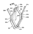
さらに、複数の電気導体は、平角断面をもった電気導体を所定形状に成形したセグメントにより提供される。図3に図示されるように、内端層の電気導体と外端層の電気導体とが、一連の電気導体をほぼU字状に成形してなる大セグメント331により提供される。そして、内中層の電気導体と外中層の電気導体とが一連の電気導体をほぼU字状に成形してなる小セグメント332により提供される。
【0043】
大セグメント331と小セグメント332とは基本セグメント33を形成する。そして、基本セグメント33を規則的にスロット35に配置して、固定子鉄心32の周りを2周するコイルが形成される。しかし、固定子巻線の引出線を構成するセグメントおよび1周めと2周めとを接続するターン部は基本セグメント33とは形状の異なる異形セグメントで構成される。そして、本実施形態の場合、異形セグメントの本数は3本となる。1周めと2周めとの接続は端層と中層の接続となるが、この接続により異形コイルエンドが形成される。
【0044】
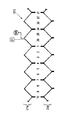
巻線仕様図を3相巻線のうちの1相であるX相について、図4、図5、図6を使用して説明する。外端層を1点鎖線、外中層を破線、内中層を実線、内端層を2点鎖線で示す。また、上段がタ−ン部を配列してなる第1コイルエンド群31aであり、下段が接合部を配列してなる第2コイルエンド群31bである。また、図の中央に横一列に並ぶ数字はスロット番号を表し、他の巻線仕様図においても同様である。
【0045】
まず、図4に示すように、セグメント33はスロット番号の1番から3スロットおきに配置される。第2コイルエンド群31bにおいて、一のスロットから出た外中層の電気導体の端部は固定子鉄心32の時計周り方向に向けて1磁極ピッチ離れた他のスロットから出た外端層の電気導体の端部と、また、一のスロットから出た内端層の電気導体の端部は固定子鉄心32の時計周り方向に向けて1磁極ピッチ離れた他のスロットから出た内中層の電気導体の端部と接合される。そして、スロットあたり2タ−ンの重ね巻の第1巻線311が形成される。
【0046】
同様に、図5に示すように、スロットあたり2タ−ンの重ね巻の第2巻線312が形成される。
【0047】
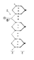
これら図4、図5の巻線311および巻線312は、図6に示すように、第1巻線311の端部33mと第2巻線312の端部33nとが連結され、スロットあたり4タ−ンの巻線315が形成される。
【0048】
ここで、第1巻線311の端部33mと第2巻線312の端部33nとを連結するターン部を有するセグメントは、基本セグメント33である大セグメント311および小セグメント312とは形状が異なっている。
【0049】
このX相の巻線では、異形セグメントは、第1巻線311の端部33mと第2巻線312の端部33nとを連結するターン部を有するセグメント、巻線端X1を有するセグメントおよび巻線端X2を有するセグメントの3つである。異形セグメントが3つに抑えられることは、次のように説明できる。
【0050】
図4に示す第1巻線311は、上述のように規則的に接合してできる環状の巻線において、1番と34番のスロット35に挿入されている小セグメント332のターン部332cを切断することによって得ることができる。
【0051】
同様に、第2巻線312は、規則的に接合してできる環状の巻線において、1番と34番のスロット35に挿入されている大セグメント331のターン部331cを切断することによって得ることができる。そして、ターン部331cの切断部の一方とターン部332cの切断部の一方とを直列に連結し、それぞれの切断部の他方を巻線端とすることにより、1本の巻線315を形成している。このように、2つの環状の巻線を2箇所で切断し、一の環の切断部と他の環の切断部とを接続して1本の巻線にすることで、4ターンの重ね巻の巻線315を形成できる。そのため、必要な異形セグメントは3つである。
【0052】
また、この異形セグメントは、第1コイルエンド群31aの1磁極ピッチ間に集中して設けることができる。本実施形態では、ターン部331cが第1巻線311を形成し、ターン部332ccが第2巻線312を形成するからである。
X相と同様にして、互いに120度ずつ位相の異なるスロットにY相、Z相が形成される。X相の巻線端X1、および図示せぬY相、Z相の巻線端Y1、Z1は、整流器5に接続され、巻線端X2は中性点として図示せぬY2、Z2と接続される。そして、図7に示すようにこれらの3相が星形結線される。図6に示した巻線では、整流器5につながる巻線端X1は、第1コイルエンド群31a側から軸方向に取り出されている。
【0053】
固定子巻線の製造工程を以下に説明する。基本セグメント33は、U字状の小セグメント332のターン部332cをU字状の大セグメント331のターン部331cが囲むように揃えられ、固定子鉄心32の軸方向側面の一方側から挿入される。その際、大セグメント331の一方の電気導体331aは固定子鉄心32の一のスロットの内端層に、小セグメント332の一方の電気導体332aは前記一のスロットの内中層に、そして、大セグメント331の他方の電気導体331bは固定子鉄心32の前記一のスロットから時計方向に1磁極ピッチ離れた他のスロットの外端層に、小セグメント332の他方の電気導体も前記他のスロットの外中層に挿入される。
【0054】
その結果、図2に示すように一のスロットには内端層側から、上述の電気導体として直線部331a、332a、332b' 、331b' が一列に配置される。ここで、332b' 、331b' は1磁極ピッチずれた他のスロット内の電気導体と対をなしている大小のセグメントの直線部である。
【0055】
挿入後、第2コイルエンド群31bにおいて、端層側に位置している電気導体は、大セグメント331が開く方向に接合部331d、331eが1.5スロット分傾けられる。そして、中層の電気導体は、小セグメント332が閉じる方向に接合部332d、332eが1.5スロット分傾けられる。
【0056】
以上の構成を、全てのスロット35のセグメント33について繰り返す。そして、第2コイルエンド群31bにおいて、外端層の接合部331e' と外中層の接合部332eとが、そして、内中層の接合部332dと内端層の接合部331d' とが溶接、超音波溶着、アーク溶接、ろう付け等の手段によって接合され、電気的に接続されている。
【0057】
なお、このセグメントは銅平板から、プレス等で略U字型形状に成形される。大セグメントと小セグメントは個別に成形しても良いし、銅平板から2本を同時に成形しても良い。また、セグメントは直線の平角断面を持つ電気導体をひねって形成される。ターン部の形状は、図3に示すようなコの字形に限らず、円弧状としてもよい。
〔第一実施形態の作用効果〕
上記構成とすることにより、第1コイルエンド群31aおよび第2コイルエンド群31bにおいて、各層の電気導体は同一方向に傾斜している。そのため、同じ層のセグメントどうしが干渉することなく、スロットあたり4タ−ンの重ね巻の巻線315を形成することができる。この時、異形セグメントは1相あたり3本のみで済み、他はすべて基本セグメント33の配置で重ね巻の巻線を構成できる。
【0058】
また、第2コイルエンド群31bに接合部を揃えることができ、作業性を改善できる。その一方で多数の接合部を、2重の環状に等間隔に配置できる。そのため、接合部間の距離の近接を抑制でき、溶接などの接合工程を容易にできる。たとえば、溶接装置の位置決め、溶接したい部位への位置合わせなどが容易になるなど、生産性の向上が可能である。
【0059】
さらに、セグメント33は大セグメント331が小セグメント332を囲むように2重のタ−ン部を形成しているので、両者をそろえて同時にスロットに導入できることや、タ−ン部の成形加工において両者を同時に製作することも可能であるので、生産性をより向上させることができる。
【0060】
また、不規則な形状となる異形セグメントを第1コイルエンド31aの1磁極ピッチ間に集中した部分に設けることによっても、生産性を向上することができる。
【0061】
以上により、セグメントを使用した固定子において、セグメント製作および巻線工程の生産性を向上させ、製造コストの低減をすることができる。
〔第二実施形態〕
第1実施形態では、スロットあたり4ターンの巻線315を示した。しかし、車両が要求される出力特性に応じ、スロットあたりの電気導体数を多くしたいという要求は、以下の第2から第4の実施形態のようにして実現することができる。
【0062】
第一実施形態では、スロットあたりの電気導体数を4本とした巻線の構造を示したが、スロットあたりの電気導体数を4本を単位とした巻線316を巻線315の径方向に積層することができる。これによって一のスロットに形成された複数個の4ターンの巻線を直列に接続することができる。
【0063】
スロットあたりの電気導体数が8本の場合の第1コイルエンド群31aの模式的な断面を図8に、また1相分の巻線仕様図を図9、図10に示す。図9は外端層側から4層分形成される巻線を表し、外端層側から第1層を1点鎖線、第2層を破線、第3層を実線、第4層を2点鎖線で示す。また、図10は第5層から第8層で形成される巻線を表し、外端層側から第5層を1点鎖線、第6層を破線、第7層を実線、第8層を2点鎖線で示す。図9の巻線および図10の巻線は第一実施形態と同様にして形成される。そして、巻線端XX1と巻線端XX2とをつなぐターン部を持つセグメントを1本配置することにより、図9、図10の巻線は直列に接続される。
【0064】
この場合も、第2コイルエンド群31bに接合部を揃えることができ、作業性を改善できる。その一方で多数の接合部を4重の環状に等間隔に配置できる。そのため、第一実施形態と同様に接合工程の生産性を確保できる。また、この実施形態では異形セグメントは1相あたり5本必要となるが、第一実施形態と同様に、それらの異形セグメントは第1コイルエンド群31aの1磁極ピッチの間に集中させることができる。
〔第三実施形態〕
第一実施形態では、スロットあたりの電気導体数を4本とした巻線315の構造を示したが、スロットあたりの電気導体数を4の倍数の場合として、第1コイルエンド群31aで巻線315が巻線317に多重に囲まれるようにセグメントのターン部を配置してもよい。
【0065】
この場合、外端層側の2本と内端層側の2本、さらに隣接する2本ずつを順次組み合わせて第一実施形態と同様の巻線を複数形成し、これらを直列に接続する。スロットあたりの導体数が8本の場合の第1コイルエンド群31aの模式的断面を図11に、また1相分の巻線仕様図を図12、図13に示す。第1層から第8層のうち、図12は第3層から第6層の構成を示し、図13は第1層、第2層、第7層、第8層の構成を示している。
【0066】
図12において、外端層側から第3層を1点鎖線、第4層を破線、第5層を実線、第6層を2点鎖線で示す。また、図13において、外端層側から第1層を1点鎖線、第2層を破線、第7層を実線、第8層を2点鎖線で示す。図9の巻線および図10の巻線は第一実施形態と同様にして形成される。図12の巻線端XX3、図13の巻線端XX4をつなぐタ−ン部を持つセグメントを1本配置することにより、図12、図13の巻線は直列に接続される。
【0067】
以上により、第2コイルエンド群31bに接合部を揃えることができ、作業性を改善できる。その一方で多数の接合部を4重の環状に等間隔に配置できる。そのため、第一実施形態と同様に接合工程の生産性を確保できる。また、この実施形態においても異形セグメントは1相あたり5本必要となるが、第一実施形態および第2実施形態と同様に、それらの異形セグメントは第1コイルエンド群31aの1磁極ピッチの間に集中させることができる。
〔第四実施形態〕
第一実施形態では、スロットあたりの電気導体数を4本とした固定子巻線の構造を示したが、スロットあたりの電気導体数を6本として、一方のコイルエンドで2つのU字状の小セグメント332、333を径方向に配置し、それらを1つの大セグメント331が囲む構造としてもよい。
【0068】
図14は、第1コイルエンド群31aの模式的な断面図であり、外端層側から第1層、第2層、第3層、第4層、第5層、第6層とする。第1層と第6層とで端層331a、331b' を形成し、第2層と第3層とで中層332a、332b' を、そして、第4層と第5層とで他の中層333a、333b' を形成する。第1層と第6層とによって外端層間をつなぐタ−ン部が形成され、その内側に第2層と第3層、および第4層と第5層をつなぐタ−ン部が配置されている。巻線仕様図を1相分を代表例として、図15、図16に示す。
【0069】
図15、図16において、外端層側から第1層を1点鎖線、第2層を細い破線、第3層を細い実線、第4層を2点鎖線、第5層を太い破線、第6層を太い実線で示す。図15に示す第1巻線313および図16に示す第2巻線314は、スロットあたり3ターンの重ね巻の巻線を形成する。第1巻線313の巻線端XX5、第2巻線314の巻線端XX6をつなぐタ−ン部を持つセグメントを1本配置することにより、図15、図16の巻線は直列に接続される。
【0070】
この場合も、巻線仕様図より明らかなように、第2コイルエンド群31bに接合部を揃えることができ、作業性を改善できる。その一方で多数の接合部を3重の環状に等間隔に配置できるため、第一実施形態と同様に接合工程の生産性を向上できる。
【0071】
また、本実施形態では、1相あたりの異形セグメントは第1巻線313の端部XX5と第2巻線314の端部XX6との接続部を有するセグメント、巻線端X1を有するセグメントおよび巻線端X2を有するセグメントの3本である。また、異形セグメントは第一実施形態から第三実施形態と同様に、第1コイルエンド群31aの1磁極ピッチの間に集中させることができる。
〔その他の実施形態〕
第一実施形態においては、第1巻線311と第2巻線322とを接続する異形セグメントは、内端層と外中層との接続とし、外端層と内中層とを引出線とした。しかし、第1巻線311と第2巻線322とを接続する異形セグメントは、外端層と内中層との接続とし、内端層と外中層とを引出線としてもよい。
【0072】
また、第一実施形態においては基本セグメント33の形状を、一方のコイルエンドにおいて、大セグメント331のターン部331cが小セグメント332のターン部332cを囲むU字状とした。しかし、棒状のセグメントをスロット35に挿入し、第一実施形態においてターン部を経由して連続線を用いて接続していた部分を接合により接続してもよい。この場合は、双方のコイルエンドにおいて、電気導体が接合により接続されて電気巻線を形成する。そして、その接合部は一方のコイルエンドにおいては、内層側と外層側の2層の環状に並んで位置し、他方のコイルエンドにおいては、外中層の電気導体と内中層の電気導体との接合部を外端層の電気導体と内端層の電気導体との接合部が囲むように位置する。
【0073】
また、一方のコイルエンドにおいて、外中層の電気導体と内中層の電気導体との接合部を、外端層の電気導体と内端層の電気導体との接合部が囲み、他方のコイルエンドにおいて、外端層の電気導体と外中層の電気導体と、および内端層の電気導体と内中層の電気導体とを連続線で接続した構成としてもよい。
【0074】
なお、上記第一から第四の実施形態では、引出線は第1コイルエンド群31a側に設けたが、引出線を接合部側である第2コイルエンド群31bに設けても構わない。
【0075】
第四実施形態では、導体数が6本としたが、導体数が6+4N(N:自然数)の場合も、内端層と外端層がタ−ン部でつながり、他は径方向に並んでいる層がタ−ン部でつながっていれば、同様の巻線構造を適用できる。
【0076】
上記の実施形態では、回転子3は12極の爪状磁極を持ち、固定子2のスロットを36個としているが、極数が変更され、それに伴いスロット数が変更された場合にも、同様の形態の巻線構造を適用できる。例えば、スロット数を2倍にして2つの三相巻線群を形成し、これらの出力を合成してもよい。
【0077】
また、スロットを周回する巻線が複数個あるときに、それらを接続して1本の巻線を形成するが、それらの接続の組合せは任意である。すなわち、車両から要求される出力特性に応じ、直列接続でも、並列接続でも、または直列と並列の複合接続でもよい。図17は直列と並列の複合接続を示したものである。図17はスロットあたり8ターンの巻線を形成した実施形態、例えば第二実施形態において、第1巻線311の端部33mと第2巻線の端部33nとをそれぞれ棒状のセグメントを用いて形成し、それら第1巻線311と第2巻線322とを並列に接続している。そして、それを他の4ターン分の巻線と直列に接続して、それらの両端を出力として各相の巻線を形成している。
【0078】
また、図18に示すように、各相それぞれ2つの巻線を形成する場合に、星形結線の巻線を2組作り、各々の整流器によって直流に変換した後、直流出力を合成してもよい。
【0079】
上記実施形態では、スロット数が36の場合を示したが、スロット数が倍になった実施形態においても同様に巻線を形成することができる。スロット数が倍になった場合の回路図を図19に示す。図19に示す例では、お互いに電気角で30°異なる巻線を、上記実施形態と同様に形成し、それらを直列に接続してX相、Y相、Z相のそれぞれの巻線を形成している。また、お互いに電気角で30°異なる巻線のそれぞれを星形結線して、各々の整流器によって直流に変換した後、直流出力を合成してもよい。なお、スロットが3倍以上に設定される場合も、同様の巻線を形成できる。
【0080】
なお、上記実施形態では、固定子巻線はX相、Y相、Z相を星形結線して形成したが、X相、Y相、Z相を三角結線して形成してもよい。あるいは、2つ以上の整流器を用いて整流後の直流出力を合成する場合に、星形結線と三角結線とを組合わせてもよい。
【0081】
また、異形セグメントの数は、固定子鉄心の周回数より1多い数となるので、第一実施形態および第四実施形態で説明したようなスロットを周回する巻線311、312、313、314のような巻線の個数より1多い数だけ必要となる。上記巻線311、312、313、314は固定子鉄心1周あたり複数ターンの巻線であるので、ターン数を維持しつつ、異形セグメントの本数を抑えることができる。
【0082】
また、上記実施形態では、セグメントは平角断面のものを用いたが、少なくともスロット内に収容される直線部331a、331b、332aおよび332bが平角断面であればよく、その他の部分は丸線断面でもよい。
【図面の簡単な説明】
【図1】本発明の第一実施形態の車両用交流発電機の断面図である。
【図2】第一実施形態の固定子の部分的な断面図である。
【図3】第一実施形態のセグメントの模式的斜視図である。
【図4】第一実施形態の固定子の部分的な巻線仕様図である。
【図5】第一実施形態の固定子の部分的な巻線仕様図である。
【図6】第一実施形態の固定子の部分的な巻線仕様図である。
【図7】第一実施形態の回路図である。
【図8】第二実施形態の固定子の第1コイルエンド群の簡略図である。
【図9】第二実施形態の固定子の部分的な巻線仕様図である。
【図10】第二実施形態の固定子の部分的な巻線仕様図である。
【図11】第三実施形態の固定子の第1コイルエンド群の簡略図である。
【図12】第三実施形態の固定子の部分的な巻線仕様図である。
【図13】第三実施形態の固定子の部分的な巻線仕様図である。
【図14】第四実施形態の固定子の第1コイルエンド群の簡略図である。
【図15】第四実施形態の固定子の部分的な巻線仕様図である。
【図16】第四実施形態の固定子の部分的な巻線仕様図である。
【図17】他の実施形態の回路図である。
【図18】他の実施形態の回路図である。
【図19】他の実施形態の回路図である。
【図20】従来の実施形態の部分的な巻線仕様図である。
【図21】従来の実施形態のスロット内での電気導体の配置を示した図である。
【符号の説明】
1 車両用交流発電機
2 固定子
3 回転子
4 フレ−ム
6 シャフト
7 ポールコア
8 界磁コイル
9、10 スリップリング
11、12 ファン
31 コイルエンド
31a 第1コイルエンド群
31b 第2コイルエンド群
32 固定子鉄心
33 セグメント
34 インシュレータ[0001]
BACKGROUND OF THE INVENTION
The present invention relates to an AC generator driven by an internal combustion engine, and relates to a vehicle AC generator stator that can be mounted on a vehicle such as a passenger car, a truck, or a ship.
[0002]
[Prior art]
In the winding process of the stator of the vehicle alternator, instead of using a continuous line, a segment made of a large number of electrical conductors bent in advance into a hairpin shape (hereinafter referred to as a turn part) is used. There is a method in which the winding is formed by inserting the stator into the slot and joining the segments together. In this configuration, since there are many joints, automation of the joining process has been indispensable in order to reduce manufacturing costs.
[0003]
As a stator of a vehicle AC generator using segments, a configuration described in International Publication 92/06527 is known. International Publication 92/06527 proposes a configuration in which joint portions between segments are annularly arranged on one side of a stator core so that joining by soldering or welding can be easily automated. According to the configuration shown here, four segments are arranged in the slot, and segments corresponding to the inversion connection portion and intermediate connection portion of each winding are individually created in advance, and these are joined together. A stator winding is formed.
[0004]
[Problems to be solved by the invention]
In International Publication 92/06527, as shown in FIG. 21, a wave winding is formed by using two segments arranged on the outer layer side and the inner layer side in one slot. FIG. 20 shows a winding specification diagram for one phase. Here, the numbers arranged in the central horizontal row in the figure represent the slot numbers. The solid line in FIG. 20 represents the electric conductor inserted at the position A in FIG. 21. Similarly, the one-dot chain line is B, the two-dot chain line is C, and the broken line is the electric conductor inserted at the D position. Represents.
[0005]
The plurality of segments constituting the winding includes a plurality of
[0006]
However, in this winding, since four electric conductors are accommodated in one slot, a wave winding coil that makes four turns around the stator core is formed. For this reason, a deformed segment having a shape different from that of the
[0007]
Further, two
[0008]
Thus, this prior art winding requires a total of five deformed segments to form a one-phase coil.
[0009]
In addition, in this winding, the two lead lines X1 and X2 are arranged at a distance of one magnetic pole pitch. This is necessary for avoiding interference with other basic segments of the Y phase and the Z phase since both the lead lines X1 and X2 are electric conductors arranged on the outer layer side of the slot.
[0010]
As noted above, prior art windings require at least five deformed segments to form a one-phase coil. This can be explained as follows. In International Publication No. 92/06527, four segments are inserted into one stator core slot and connected by a connecting
[0011]
The segment insertion process and the segment end joining process for forming an annular winding ring that goes around the stator iron core are the same for all segments. Form another annular winding for the same slot as the above slot, and another two windings at a position shifted by three slots from the two windings, for a total of four turns. Annular windings are formed.
[0012]
In order to make an annular winding that wraps around the stator core four turns into one winding, each ring is cut at one place (four rings for a total of four places) Need to connect. A total of five deformed segments are required, three having a connection portion with another ring and two having a lead-out portion as an output end.
[0013]
These five deformed segments cannot be concentrated on the coil ends between the basic one magnetic pole pitches. This is because, as described above, the four windings of the annular winding are divided into two sets whose positions are shifted by three slots from each other, and the four rings do not overlap at the coil ends arranged in the radial direction. .
[0014]
Of course, if the number of segments per slot is two, which is half of the above example, the deformed segments can be concentrated on the coil ends between one magnetic pole pitch. However, if the number of turns per slot is reduced, it is not possible to secure sufficient output in the low-speed rotation region necessary for a vehicle AC generator.
[0015]
In the configuration shown in FIG. 20, the electrical conductors coming out from the inner layer side and the electrical conductors coming out from the outer layer side are joined by the
[0016]
Further, in the stator winding of International Publication No. 92/06527, the
[0017]
As described above, the increase in the number of deformed segments and the reduction in the interval between the joint portions complicate the process of assembling the segments to the stator core and increase the manufacturing cost, so that the original purpose cannot be achieved.
[0018]
In addition, in International Publication 92/06527, there is a description that a stator winding can be made into a lap winding using a segment. However, International Publication No. 92/06527 does not describe to the extent that it is possible to perform wrapping using segments.
[0019]
An object of the present invention is to provide a stator that secures the number of turns per slot with a small number of laps.
[0020]
The present invention has been made in view of the above-described problems of the prior art, and an object thereof is to provide a stator that facilitates a winding process using a segment.
[0021]
Specifically, the present invention provides a stator with few unique segments while ensuring the number of turns per slot.
[0022]
[Means for Solving the Problems]
The stator winding is configured by joining a plurality of segments made of electrical conductors,
The segment is composed of a basic segment having a regular shape and a deformed segment having a shape different from that of the basic segment.
The basic segment is U-shaped having a turn part,
A first coil end group is formed on one of the axial end faces of the stator core by arranging the turn portions of the segments;
A second coil end group is formed on the other of the axial end faces of the stator core by joining the end portions of the segments so as to form a lap winding to form a plurality of adjacent layer coil ends,
The basic segment is regularly arranged in a slot to form a coil that makes two rounds around the stator core, and is a deformed segment having a different shape from the basic segment. This is a stator for a vehicle alternator characterized in that a turn portion connecting the first and second turns is formed.
[0023]
2. The vehicle alternator according to
[0024]
According to a third aspect of the present invention, in the vehicle AC generator according to the first or second aspect, the even-numbered electric conductors having a minimum of four are arranged only in the radial direction in the slot. It is a stator.
[0025]
According to a fourth aspect of the present invention, in the stator for an automotive alternator according to the third aspect, the joint portion in the second coil end group is arranged in a double, triple or quadruple annular shape. is there.
[0026]
DETAILED DESCRIPTION OF THE INVENTION
Hereinafter, the AC generator for vehicles of this invention is explained based on each example shown in a figure. [First embodiment]
FIGS. 1 to 7 show a first embodiment of the present invention. FIG. 1 is a cross-sectional view of the main part of an AC generator for a vehicle, and FIGS. 2 to 6 are explanatory views of the stator of this embodiment.
[0027]
A
[0028]
The
[0029]
The Landel-
[0030]
A
[0031]
The
[0032]
FIG. 2 is a partial cross-sectional view of the
[0033]
The stator windings installed in the
[0034]
One electrical conductor in each slot is paired with one other electrical conductor in another slot separated by a predetermined magnetic pole pitch.
[0035]
In particular, in order to secure a gap between the plurality of electric conductors in the coil end portion and arrange them in an aligned manner, the electric conductors of a predetermined layer in one slot are connected to other slots in another slot separated by a predetermined magnetic pole pitch. It is paired with the electrical conductor of the layer.
[0036]
For example, the
[0037]
The paired electrical conductors are connected via the
[0038]
Accordingly, at one end of the
[0039]
On the other hand, the inner-layer
[0040]
Therefore, at the other end portion of the
[0041]
In this way, at the other end of the
[0042]
Further, the plurality of electric conductors are provided by segments obtained by shaping an electric conductor having a rectangular cross section into a predetermined shape. As shown in FIG. 3, the inner end layer electric conductor and the outer end layer electric conductor are provided by a
[0043]
The
[0044]
The winding specification diagram will be described with reference to FIGS. 4, 5, and 6 for the X phase, which is one of the three-phase windings. The outer end layer is indicated by a one-dot chain line, the outer middle layer is indicated by a broken line, the inner middle layer is indicated by a solid line, and the inner end layer is indicated by a two-dot chain line. The upper stage is a first
[0045]
First, as shown in FIG. 4, the
[0046]
Similarly, as shown in FIG. 5, a second winding 312 having two turns per slot is formed.
[0047]
As shown in FIG. 6, the winding 311 and the winding 312 of FIGS. 4 and 5 are connected to the
[0048]
Here, the segment having the turn portion connecting the
[0049]
In this X-phase winding, the deformed segment includes a segment having a turn portion connecting the
[0050]
The first winding 311 shown in FIG. 4 is an annular winding formed by regular joining as described above, and cuts the
[0051]
Similarly, the second winding 312 is obtained by cutting the
[0052]
Further, the deformed segment can be provided concentrated between one magnetic pole pitch of the first
Similarly to the X phase, the Y phase and the Z phase are formed in slots whose phases are different from each other by 120 degrees. The X-phase winding end X1 and the Y-phase and Z-phase winding ends Y1 and Z1 (not shown) are connected to the
[0053]
The manufacturing process of the stator winding will be described below. The
[0054]
As a result, as shown in FIG. 2, the
[0055]
After the insertion, in the second
[0056]
The above configuration is repeated for all the
[0057]
In addition, this segment is shape | molded by the press etc. from the copper flat plate in the substantially U shape. The large segment and the small segment may be formed separately, or two pieces may be formed simultaneously from a copper flat plate. The segment is formed by twisting an electric conductor having a straight rectangular cross section. The shape of the turn portion is not limited to the U-shape as shown in FIG. 3 and may be an arc shape.
[Operational effects of the first embodiment]
With the above configuration, in the first
[0058]
Moreover, a joint part can be arranged in the 2nd
[0059]
Further, since the
[0060]
Moreover, productivity can be improved also by providing the irregular segment which becomes an irregular shape in the part concentrated between 1 magnetic pole pitch of the
[0061]
As described above, in the stator using the segment, the productivity of the segment manufacturing and winding process can be improved, and the manufacturing cost can be reduced.
[Second Embodiment]
In the first embodiment, the winding 315 having four turns per slot is shown. However, the request to increase the number of electrical conductors per slot according to the output characteristics required by the vehicle can be realized as in the following second to fourth embodiments.
[0062]
In the first embodiment, the structure of the winding with four electrical conductors per slot is shown. However, the winding 316 with the number of electrical conductors per slot as four units is arranged in the radial direction of the winding 315. Can be stacked. As a result, a plurality of 4-turn windings formed in one slot can be connected in series.
[0063]
FIG. 8 shows a schematic cross section of the first
[0064]
Also in this case, the joint portion can be aligned with the second
[Third embodiment]
In the first embodiment, the structure of the winding 315 in which the number of electrical conductors per slot is four is shown. However, when the number of electrical conductors per slot is a multiple of 4, the first
[0065]
In this case, a plurality of windings similar to those in the first embodiment are formed by sequentially combining two pieces on the outer end layer side, two pieces on the inner end layer side, and two adjacent ones, and these are connected in series. FIG. 11 shows a schematic cross section of the first
[0066]
In FIG. 12, from the outer end layer side, the third layer is indicated by a one-dot chain line, the fourth layer is indicated by a broken line, the fifth layer is indicated by a solid line, and the sixth layer is indicated by a two-dot chain line. In FIG. 13, the first layer is indicated by a one-dot chain line, the second layer is indicated by a broken line, the seventh layer is indicated by a solid line, and the eighth layer is indicated by a two-dot chain line from the outer end layer side. The winding in FIG. 9 and the winding in FIG. 10 are formed in the same manner as in the first embodiment. The windings shown in FIGS. 12 and 13 are connected in series by arranging one segment having a turn portion connecting the winding end XX3 in FIG. 12 and the winding end XX4 in FIG.
[0067]
As described above, the joint portion can be aligned with the second
[Fourth embodiment]
In the first embodiment, the structure of the stator winding with four electrical conductors per slot is shown. However, the number of electrical conductors per slot is six, and two U-shapes are formed at one coil end. The
[0068]
FIG. 14 is a schematic cross-sectional view of the first
[0069]
15 and 16, from the outer end layer side, the first layer is a one-dot chain line, the second layer is a thin broken line, the third layer is a thin solid line, the fourth layer is a two-dot chain line, the fifth layer is a thick broken line, Six layers are indicated by thick solid lines. The first winding 313 shown in FIG. 15 and the second winding 314 shown in FIG. 16 form a three-turn winding per slot. The windings shown in FIGS. 15 and 16 are connected in series by arranging one segment having a turn portion connecting the winding end XX5 of the first winding 313 and the winding end XX6 of the second winding 314. Is done.
[0070]
Also in this case, as is apparent from the winding specification diagram, the joint portion can be aligned with the second
[0071]
In the present embodiment, the deformed segment per phase includes a segment having a connection portion between the end XX5 of the first winding 313 and the end XX6 of the second winding 314, a segment having the winding end X1, and a winding. Three segments having line ends X2. Also, the deformed segments can be concentrated between one magnetic pole pitch of the first
[Other Embodiments]
In the first embodiment, the deformed segment connecting the first winding 311 and the second winding 322 is a connection between the inner end layer and the outer middle layer, and the outer end layer and the inner middle layer are the lead lines. However, the odd-shaped segment connecting the first winding 311 and the second winding 322 may be a connection between the outer end layer and the inner middle layer, and the inner end layer and the outer middle layer may be the lead lines.
[0072]
In the first embodiment, the shape of the
[0073]
Also, at one coil end, the junction between the outer middle layer electrical conductor and the inner middle layer electrical conductor is surrounded by the junction between the outer end layer electrical conductor and the inner end layer electrical conductor, and at the other coil end. The outer end layer electrical conductor and the outer middle layer electrical conductor, and the inner end layer electrical conductor and the inner middle layer electrical conductor may be connected by a continuous line.
[0074]
In the first to fourth embodiments, the lead wire is provided on the first
[0075]
In the fourth embodiment, the number of conductors is six. However, when the number of conductors is 6 + 4N (N: natural number), the inner end layer and the outer end layer are connected at the turn portion, and the others are arranged in the radial direction. If the layers are connected at the turn, the same winding structure can be applied.
[0076]
In the above embodiment, the
[0077]
Further, when there are a plurality of windings that circulate around the slot, they are connected to form one winding, but the combination of these connections is arbitrary. That is, depending on the output characteristics required from the vehicle, it may be connected in series, connected in parallel, or combined in series and parallel. FIG. 17 shows a composite connection in series and parallel. FIG. 17 shows an embodiment in which windings of 8 turns per slot are formed, for example, in the second embodiment, the
[0078]
As shown in FIG. 18, when two windings are formed for each phase, two sets of star connection windings are formed, converted into direct current by each rectifier, and then combined with the direct current output. Good.
[0079]
Although the case where the number of slots is 36 has been described in the above embodiment, windings can be formed similarly in an embodiment where the number of slots is doubled. FIG. 19 shows a circuit diagram when the number of slots is doubled. In the example shown in FIG. 19, windings different in electrical angle from each other by 30 ° are formed in the same manner as in the above embodiment, and they are connected in series to form respective windings of X phase, Y phase, and Z phase is doing. Alternatively, the windings that differ in electrical angle from each other by 30 ° may be star-connected and converted into direct current by each rectifier, and then the direct current output may be synthesized. Note that the same winding can be formed even when the slot is set to be three times or more.
[0080]
In the above embodiment, the stator winding is formed by star connection of the X phase, Y phase, and Z phase, but may be formed by triangular connection of the X phase, Y phase, and Z phase. Alternatively, when the rectified DC output is synthesized using two or more rectifiers, a star connection and a triangular connection may be combined.
[0081]
In addition, since the number of deformed segments is one more than the number of turns of the stator core, the
[0082]
Moreover, in the said embodiment, although the segment used the thing of a flat cross section, the
[Brief description of the drawings]
FIG. 1 is a cross-sectional view of an automotive alternator according to a first embodiment of the present invention.
FIG. 2 is a partial cross-sectional view of the stator according to the first embodiment.
FIG. 3 is a schematic perspective view of a segment according to the first embodiment.
FIG. 4 is a partial winding specification diagram of the stator according to the first embodiment.
FIG. 5 is a partial winding specification diagram of the stator according to the first embodiment.
FIG. 6 is a partial winding specification diagram of the stator of the first embodiment.
FIG. 7 is a circuit diagram of the first embodiment.
FIG. 8 is a simplified diagram of a first coil end group of the stator of the second embodiment.
FIG. 9 is a partial winding specification diagram of the stator of the second embodiment.
FIG. 10 is a partial winding specification diagram of the stator according to the second embodiment.
FIG. 11 is a simplified diagram of a first coil end group of a stator according to a third embodiment.
FIG. 12 is a partial winding specification diagram of the stator according to the third embodiment.
FIG. 13 is a partial winding specification diagram of the stator according to the third embodiment.
FIG. 14 is a simplified diagram of a first coil end group of a stator according to a fourth embodiment.
FIG. 15 is a partial winding specification diagram of the stator of the fourth embodiment.
FIG. 16 is a partial winding specification diagram of the stator according to the fourth embodiment.
FIG. 17 is a circuit diagram of another embodiment.
FIG. 18 is a circuit diagram of another embodiment.
FIG. 19 is a circuit diagram of another embodiment.
FIG. 20 is a partial winding specification diagram of the conventional embodiment.
FIG. 21 is a diagram showing an arrangement of electric conductors in a slot according to a conventional embodiment.
[Explanation of symbols]
1 AC generator for vehicles
2 Stator
3 Rotor
4 frames
6 Shaft
7 Pole core
8 Field coil
9, 10 Slip ring
11, 12 fans
31 Coil end
31a First coil end group
31b Second coil end group
32 Stator core
33 segments
34 Insulator
Claims (4)
前記固定子巻線は、電気導体よりなる複数のセグメントを接合して構成されており、
前記セグメントは、規則的な形状の基本セグメントと、前記基本セグメントと形状を異にする異形セグメントとから構成され、
前記基本セグメントは、ターン部を有するU字状であり、
前記固定子鉄心の軸方向端面の一方に、前記セグメントのターン部を配置してなる第1コイルエンド群が形成され、
前記固定子鉄心の軸方向端面の他方に、重ね巻を形成するように前記セグメントの端部を接合して複数の隣接層コイルエンドを形成してなる第2コイルエンド群が形成され、
前記基本セグメントを規則的にスロットに配置して前記固定子鉄心のまわりを2周するコイルが形成され、前記基本セグメントとは形状の異なる異形セグメントで、前記固定子巻線の引出線と1周めと2周めとを接続するターン部とが構成されることを特徴とする車両用交流発電機の固定子。In a vehicle alternator stator having a stator core having a plurality of slots and a multiphase stator winding mounted in the slots,
The stator winding is configured by joining a plurality of segments made of electrical conductors,
The segment is composed of a basic segment having a regular shape and a deformed segment having a shape different from that of the basic segment.
The basic segment is U-shaped having a turn part,
A first coil end group is formed on one of the axial end faces of the stator core by arranging the turn portions of the segments;
A second coil end group is formed on the other of the axial end faces of the stator core by joining the end portions of the segments so as to form a lap winding to form a plurality of adjacent layer coil ends,
The basic segment is regularly arranged in a slot to form a coil that makes two rounds around the stator core, and is a deformed segment having a different shape from the basic segment. A vehicle alternator stator characterized by comprising a turn portion connecting the first and second laps.
Priority Applications (1)
| Application Number | Priority Date | Filing Date | Title |
|---|---|---|---|
| JP13995099A JP3744258B2 (en) | 1997-09-26 | 1999-05-20 | Vehicle alternator stator |
Applications Claiming Priority (4)
| Application Number | Priority Date | Filing Date | Title |
|---|---|---|---|
| JP27975197 | 1997-09-26 | ||
| JP9-279751 | 1997-09-26 | ||
| JP11-999999 | 1998-11-19 | ||
| JP13995099A JP3744258B2 (en) | 1997-09-26 | 1999-05-20 | Vehicle alternator stator |
Related Parent Applications (1)
| Application Number | Title | Priority Date | Filing Date |
|---|---|---|---|
| JP11417498A Division JP3303773B2 (en) | 1997-05-26 | 1998-04-08 | Stator of vehicle alternator |
Publications (2)
| Publication Number | Publication Date |
|---|---|
| JPH11346448A JPH11346448A (en) | 1999-12-14 |
| JP3744258B2 true JP3744258B2 (en) | 2006-02-08 |
Family
ID=37308895
Family Applications (1)
| Application Number | Title | Priority Date | Filing Date |
|---|---|---|---|
| JP13995099A Expired - Lifetime JP3744258B2 (en) | 1997-09-26 | 1999-05-20 | Vehicle alternator stator |
Country Status (4)
| Country | Link |
|---|---|
| US (3) | US5936326A (en) |
| EP (3) | EP1237254B1 (en) |
| JP (1) | JP3744258B2 (en) |
| DE (1) | DE69811564T3 (en) |
Families Citing this family (113)
| Publication number | Priority date | Publication date | Assignee | Title |
|---|---|---|---|---|
| EP1237254B1 (en) | 1997-05-26 | 2008-06-04 | Denso Corporation | Alternator for vehicle |
| DE19736645C2 (en) * | 1997-08-22 | 1999-12-02 | Gruendl & Hoffmann | Wanderfeldmaschine |
| JP3769990B2 (en) * | 1999-08-06 | 2006-04-26 | 株式会社デンソー | Conductor segment bonding type rotating electrical machine and method for manufacturing the same |
| JP3899685B2 (en) * | 1998-06-26 | 2007-03-28 | 株式会社デンソー | Stator for vehicle alternator and manufacturing method thereof |
| JP3427748B2 (en) | 1998-10-09 | 2003-07-22 | 株式会社デンソー | AC generator for vehicles |
| JP3284981B2 (en) * | 1998-11-02 | 2002-05-27 | 株式会社デンソー | Method for manufacturing vehicle alternator and stator thereof |
| JP3250533B2 (en) * | 1998-11-25 | 2002-01-28 | 株式会社デンソー | Stator for vehicle alternator and method of manufacturing the same |
| JP3199068B2 (en) * | 1999-03-31 | 2001-08-13 | 株式会社デンソー | Stator manufacturing equipment |
| JP4029519B2 (en) * | 1999-04-12 | 2008-01-09 | 株式会社デンソー | Vehicle alternator stator |
| JP2001037131A (en) * | 1999-07-15 | 2001-02-09 | Mitsubishi Electric Corp | Vehicle ac generator |
| JP6614067B2 (en) | 2016-08-24 | 2019-12-04 | 株式会社デンソー | Rotating electric machine stator |
| JP3383251B2 (en) * | 1999-12-27 | 2003-03-04 | 三菱電機株式会社 | Vehicle alternator stator |
| JP3347116B2 (en) * | 2000-01-12 | 2002-11-20 | 三菱電機株式会社 | Alternator |
| EP1109296B1 (en) * | 1999-12-14 | 2003-06-11 | Mitsubishi Denki Kabushiki Kaisha | Alternator |
| JP3347115B2 (en) * | 1999-12-20 | 2002-11-20 | 三菱電機株式会社 | AC generator |
| JP2001211588A (en) * | 2000-01-27 | 2001-08-03 | Mitsubishi Electric Corp | Ac generator |
| JP3448253B2 (en) * | 2000-01-31 | 2003-09-22 | 三菱電機株式会社 | AC generator |
| JP4462392B2 (en) * | 2000-02-23 | 2010-05-12 | 三菱電機株式会社 | Method of manufacturing an alternator stator |
| JP4318827B2 (en) * | 2000-02-24 | 2009-08-26 | 三菱電機株式会社 | AC generator |
| DE10008803A1 (en) * | 2000-02-25 | 2001-09-13 | Siemens Ag | Electric rotary machine |
| JP4014071B2 (en) * | 2000-03-13 | 2007-11-28 | 三菱電機株式会社 | AC generator, winding assembly thereof, and method of manufacturing winding assembly |
| JP3783832B2 (en) | 2000-03-30 | 2006-06-07 | 三菱電機株式会社 | AC generator for vehicles |
| JP2001286082A (en) * | 2000-04-03 | 2001-10-12 | Mitsubishi Electric Corp | Stator of ac generator |
| US6943477B1 (en) | 2000-04-27 | 2005-09-13 | Denso Corporation | Stator of rotary electric machine and method for making the same |
| DE10119776A1 (en) * | 2000-04-27 | 2001-11-08 | Denso Corp | Stator of an induction machine and method for its production |
| JP4461590B2 (en) * | 2000-08-25 | 2010-05-12 | 株式会社デンソー | Vehicle alternator |
| JP3476438B2 (en) * | 2001-01-19 | 2003-12-10 | 三菱電機株式会社 | AC generator for vehicles |
| JP3633494B2 (en) * | 2001-02-20 | 2005-03-30 | 株式会社デンソー | Rotating electric machine |
| JP3566665B2 (en) * | 2001-04-06 | 2004-09-15 | 三菱電機株式会社 | Rotating machine stator |
| JP3593059B2 (en) * | 2001-05-28 | 2004-11-24 | 三菱電機株式会社 | AC generator for vehicles |
| US7064466B2 (en) * | 2001-11-27 | 2006-06-20 | Denso Corporation | Brushless rotary electric machine having tandem rotary cores |
| US6882077B2 (en) * | 2002-12-19 | 2005-04-19 | Visteon Global Technologies, Inc. | Stator winding having cascaded end loops |
| US6787961B2 (en) | 2002-12-19 | 2004-09-07 | Visteon Global Technologies, Inc. | Automotive alternator stator assembly with varying end loop height between layers |
| US6930426B2 (en) * | 2003-11-26 | 2005-08-16 | Visteon Global Technologies, Inc. | Alternator stator having a multiple filar construction to improve convective cooling |
| US6750581B2 (en) * | 2002-01-24 | 2004-06-15 | Visteon Global Technologies, Inc. | Automotive alternator stator assembly with rectangular continuous wire |
| US7129612B2 (en) * | 2002-01-24 | 2006-10-31 | Visteon Global Technologies, Inc. | Stator assembly with cascaded winding and method of making same |
| US7170211B2 (en) * | 2002-01-24 | 2007-01-30 | Visteon Global Technologies, Inc. | Stator winding having transitions |
| GB2389717B (en) * | 2002-01-24 | 2004-07-28 | Visteon Global Tech Inc | Automotive alternator stator assembly and winding method |
| KR100450897B1 (en) * | 2002-02-27 | 2004-10-01 | 미쓰비시덴키 가부시키가이샤 | Stator of dynamo-electric machine |
| JP4019951B2 (en) * | 2002-03-01 | 2007-12-12 | 株式会社デンソー | Manufacturing method of winding of rotating electrical machine and processing method of winding recess |
| DE10321956B4 (en) * | 2002-05-15 | 2013-09-12 | Remy Inc. | Windings of rectangular copper hairpins in multiple sets for electrical machines |
| US20030214190A1 (en) * | 2002-05-15 | 2003-11-20 | Delco Remy America | Connection device for hairpin wound electric machines |
| DE10326095A1 (en) * | 2002-06-12 | 2004-04-15 | Denso Corp., Kariya | Coil of sequentially connected segments for a rotating electrical machine |
| US20050023909A1 (en) * | 2002-06-13 | 2005-02-03 | Cromas Joseph Charles | Automotive generator |
| US20040000820A1 (en) * | 2002-06-13 | 2004-01-01 | Cromas Joseph Charles | Automotive generator |
| JP3783660B2 (en) * | 2002-06-25 | 2006-06-07 | 株式会社デンソー | Segment sequential joining stator coil of rotating electrical machine |
| JP2004048890A (en) * | 2002-07-11 | 2004-02-12 | Denso Corp | Rotary electric machine |
| JP3791471B2 (en) | 2002-07-12 | 2006-06-28 | 株式会社デンソー | Segment sequential stator coil type rotating electrical machine |
| JP3815674B2 (en) | 2002-07-15 | 2006-08-30 | 株式会社デンソー | Segment sequential stator coil type rotating electrical machine |
| US6825586B2 (en) * | 2002-10-29 | 2004-11-30 | Remy, Inc. | One piece stator lead and terminal insulator |
| JP2004229460A (en) * | 2003-01-27 | 2004-08-12 | Mitsubishi Electric Corp | Stator of rotary electric machine |
| US6949857B2 (en) * | 2003-03-14 | 2005-09-27 | Visteon Global Technologies, Inc. | Stator of a rotary electric machine having stacked core teeth |
| JP2004320906A (en) * | 2003-04-17 | 2004-11-11 | Denso Corp | Vehicular alternator |
| DE10329678A1 (en) * | 2003-07-01 | 2005-02-03 | Siemens Ag | Electric motor for driving a vehicle, in particular rail drives, and a drive with such an electric motor |
| US6922001B2 (en) * | 2003-12-02 | 2005-07-26 | Visteon Global Technologies, Inc. | Process for assembling an alternator stator with clips that allows radial insertion of square wire with small slot openings |
| EP1750351B1 (en) * | 2004-05-28 | 2019-12-04 | Mitsubishi Denki Kabushiki Kaisha | Alternator for vehicle |
| US7081697B2 (en) * | 2004-06-16 | 2006-07-25 | Visteon Global Technologies, Inc. | Dynamoelectric machine stator core with mini caps |
| US7386931B2 (en) * | 2004-07-21 | 2008-06-17 | Visteon Global Technologies, Inc. | Method of forming cascaded stator winding |
| US7269888B2 (en) | 2004-08-10 | 2007-09-18 | Visteon Global Technologies, Inc. | Method of making cascaded multilayer stator winding with interleaved transitions |
| JP4424163B2 (en) * | 2004-11-10 | 2010-03-03 | 株式会社デンソー | Vehicle alternator |
| US20060152100A1 (en) * | 2005-01-07 | 2006-07-13 | Visteon Global Technologies, Inc. | Vehicle alternator having reduced windings |
| ATE349094T1 (en) * | 2005-03-17 | 2007-01-15 | Zahnradfabrik Friedrichshafen | STATOR FOR AN ELECTRICAL MACHINE |
| JP4501762B2 (en) * | 2005-04-18 | 2010-07-14 | 株式会社デンソー | Vehicle alternator |
| JP2007020302A (en) * | 2005-07-07 | 2007-01-25 | Denso Corp | Dynamo electric machine for vehicle |
| JP4640008B2 (en) * | 2005-07-15 | 2011-03-02 | 株式会社デンソー | Rotating electric machine for vehicles |
| JP4453670B2 (en) * | 2006-02-24 | 2010-04-21 | 株式会社デンソー | Vehicle alternator stator |
| JP2007295697A (en) * | 2006-04-24 | 2007-11-08 | Toyota Motor Corp | Stator of rotary electric machine and component for use in stator |
| JP4450235B2 (en) * | 2006-05-25 | 2010-04-14 | 株式会社デンソー | AC generator |
| JP4692439B2 (en) * | 2006-08-22 | 2011-06-01 | 株式会社デンソー | AC generator for vehicles |
| JP4910572B2 (en) * | 2006-08-30 | 2012-04-04 | 株式会社デンソー | Rotating electric machine for vehicles |
| JP4483845B2 (en) * | 2006-09-12 | 2010-06-16 | 株式会社デンソー | Vehicle alternator |
| FR2908941B1 (en) * | 2006-11-22 | 2014-03-14 | Valeo Equip Electr Moteur | METHOD FOR PRODUCING A FAN DEVICE FOR A ROTATING ELECTRIC MACHINE AND A FAN DEVICE FOR CARRYING OUT SAID METHOD |
| JP4475470B2 (en) * | 2007-04-05 | 2010-06-09 | 三菱電機株式会社 | Insulation structure of coil part of rotating electrical machine |
| FR2918815A1 (en) * | 2007-07-11 | 2009-01-16 | Valeo Equip Electr Moteur | POLYPHASE STATOR FOR INTERNAL VENTILATION ROTATING ELECTRIC MACHINE AND ROTATING ELECTRIC MACHINE COMPRISING SUCH A STATOR. |
| RU2483413C2 (en) * | 2007-08-03 | 2013-05-27 | Альстом Текнолоджи Лтд | Electric machine, in particular, three-phase asynchronous hydrogenerator |
| JP4873261B2 (en) * | 2007-11-20 | 2012-02-08 | 株式会社デンソー | Method for manufacturing coil assembly of rotating electrical machine |
| JP4396761B2 (en) | 2007-11-26 | 2010-01-13 | 株式会社デンソー | Rotating electric machine stator and rotating electric machine |
| EP2063515A3 (en) * | 2007-11-26 | 2010-10-27 | Denso Corporation | Stator for rotary electric machine, and rotary electric machine using the stator |
| JP4479788B2 (en) | 2007-12-20 | 2010-06-09 | 株式会社デンソー | Coil forming method and coil forming die |
| JP5083329B2 (en) * | 2007-12-27 | 2012-11-28 | アイシン・エィ・ダブリュ株式会社 | Stator and rotating electric machine using the same |
| JP5167939B2 (en) * | 2008-05-12 | 2013-03-21 | 株式会社デンソー | Method for manufacturing coil assembly of rotating electrical machine |
| JP5332347B2 (en) * | 2008-06-30 | 2013-11-06 | 株式会社デンソー | Coil wire rod for coil assembly of rotating electrical machine |
| JP5260399B2 (en) * | 2009-04-24 | 2013-08-14 | 日立オートモティブシステムズ株式会社 | Rotating electric machine for driving vehicle and vehicle using the same |
| US8456053B2 (en) * | 2009-08-28 | 2013-06-04 | GM Global Technology Operations LLC | Insulation assembly for a stator core |
| JP5134064B2 (en) * | 2010-11-18 | 2013-01-30 | トヨタ自動車株式会社 | Rotating electric machine |
| US9130430B2 (en) * | 2011-03-18 | 2015-09-08 | Remy Technologies Llc | Electric machine with fully enclosed in-slot conductors |
| JP5565381B2 (en) * | 2011-06-17 | 2014-08-06 | 株式会社デンソー | Rotating electric machine stator |
| DE102012108943A1 (en) | 2011-09-24 | 2013-03-28 | Denso Corporation | Rotating electrical machine |
| JP5502913B2 (en) | 2012-01-23 | 2014-05-28 | 三菱電機株式会社 | Rotating electric machine |
| US9502931B2 (en) | 2012-03-23 | 2016-11-22 | Asmo Co., Ltd. | Brushless motor |
| JP5724984B2 (en) * | 2012-10-19 | 2015-05-27 | トヨタ自動車株式会社 | Rotating electric machine stator |
| US20140111055A1 (en) * | 2012-10-23 | 2014-04-24 | Remy Technologies, L.L.C. | Conductor with divot for improved form factor |
| JP6094149B2 (en) * | 2012-10-31 | 2017-03-15 | アイシン精機株式会社 | Wave winding of three-phase rotating electric machine |
| DE102012223711A1 (en) * | 2012-12-19 | 2014-06-26 | Robert Bosch Gmbh | Electric machine |
| DE102012223705A1 (en) * | 2012-12-19 | 2014-06-26 | Robert Bosch Gmbh | Electric machine |
| JP5720715B2 (en) | 2013-03-29 | 2015-05-20 | 株式会社デンソー | Rotating electric machine |
| JP5939446B2 (en) | 2013-03-29 | 2016-06-22 | 株式会社デンソー | Stator, rotating electric machine including the stator, and method for manufacturing the stator |
| JP5907128B2 (en) | 2013-08-21 | 2016-04-20 | 株式会社デンソー | Rotating electric machine stator |
| EP3048704B1 (en) | 2013-09-18 | 2022-01-12 | Mitsubishi Electric Corporation | Rotating electrical machine stator |
| JP5748878B2 (en) * | 2014-03-13 | 2015-07-15 | 三菱電機株式会社 | Rotating electric machine |
| FR3019947B1 (en) * | 2014-04-10 | 2017-12-08 | Moteurs Leroy-Somer | STATOR OF ROTATING ELECTRIC MACHINE. |
| FR3019948B1 (en) | 2014-04-10 | 2017-12-22 | Moteurs Leroy-Somer | ROTOR OF ELECTRIC ROTATING MACHINE. |
| FR3020521B1 (en) * | 2014-04-29 | 2016-06-03 | Nicolas Langlard | ROTATING ELECTRIC MACHINE STATOR WITH OPTIMIZED WINDING |
| JP6405775B2 (en) | 2014-08-07 | 2018-10-17 | 株式会社デンソー | Double stator rotary electric machine |
| JP6222032B2 (en) | 2014-10-14 | 2017-11-01 | 株式会社デンソー | Rotating electric machine |
| JP6591198B2 (en) * | 2015-05-22 | 2019-10-16 | 日立オートモティブシステムズ株式会社 | Rotating electric machine stator |
| JP6601038B2 (en) | 2015-07-28 | 2019-11-06 | 株式会社デンソー | Manufacturing method of rotating electrical machine |
| JP6658559B2 (en) | 2017-01-13 | 2020-03-04 | 株式会社デンソー | Rotating electric machine stator |
| JP6642494B2 (en) * | 2017-03-10 | 2020-02-05 | トヨタ自動車株式会社 | Manufacturing equipment for stators of rotating electric machines |
| DE102018219816A1 (en) * | 2018-11-19 | 2020-05-20 | Mahle International Gmbh | Electrical machine, in particular for a vehicle |
| DE102018219817A1 (en) * | 2018-11-19 | 2020-05-20 | Mahle International Gmbh | Electrical machine, in particular for a vehicle |
| JPWO2020202711A1 (en) * | 2019-03-29 | 2020-10-08 | ||
| US11990815B2 (en) * | 2020-07-31 | 2024-05-21 | Copenhagen Atomics A/S | Canned rotodynamic flow machine for a molten salt nuclear reactor and an active magnetic bearing for use in a flow machine for a molten salt nuclear reactor |
Family Cites Families (35)
| Publication number | Priority date | Publication date | Assignee | Title |
|---|---|---|---|---|
| GB191123548A (en) * | 1911-10-25 | 1912-10-10 | P R Jackson And Company Ltd | Improvements in the Windings of Electric Generators and other Electrical Machines. |
| DE270642C (en) * | 1911-12-23 | |||
| US1826295A (en) * | 1928-06-14 | 1931-10-06 | Vincent G Apple | Dynamo electric machine element |
| CH149526A (en) * | 1930-09-09 | 1931-09-15 | Oerlikon Maschf | Grid winding for AC machines. |
| US2407935A (en) * | 1944-05-25 | 1946-09-17 | Chrysler Corp | Electrical machine |
| US2928963A (en) † | 1956-06-06 | 1960-03-15 | Gen Motors Corp | Dynamoelectric machine |
| GB863073A (en) * | 1957-03-12 | 1961-03-15 | Westinghouse Electric Corp | Improvements in or relating to dynamo electric machines |
| CH546501A (en) * | 1972-06-20 | 1974-02-28 | Bbc Brown Boveri & Cie | METHOD OF MANUFACTURING BARRIERS FOR THE STATOR WINDING OF A ROTATING ELECTRIC HIGH VOLTAGE MACHINE. |
| JPS55141947A (en) * | 1979-04-24 | 1980-11-06 | Toshiba Corp | Insulation of channel of rotary electric machine |
| JPS57129141A (en) * | 1981-02-03 | 1982-08-11 | Kazuo Sano | Single layer half-wound coil |
| JPS57132743A (en) * | 1981-02-09 | 1982-08-17 | Nippon Denso Co Ltd | Ac generator for vehicle |
| JPS59127546A (en) * | 1983-01-10 | 1984-07-23 | Mitsubishi Electric Corp | Armature coil for rotary electric machine |
| US4425519A (en) * | 1983-04-19 | 1984-01-10 | General Electric Company | Crack resistant armor termination for pole face winding bars |
| JPS61221561A (en) * | 1985-03-27 | 1986-10-01 | Nippon Denso Co Ltd | Flat rotary electric machine |
| JPH0744797B2 (en) * | 1986-05-20 | 1995-05-15 | 日本電装株式会社 | Armature coil |
| US4907541A (en) | 1986-06-16 | 1990-03-13 | Thompson Paul L | Pet restraint |
| US4908541A (en) * | 1986-08-28 | 1990-03-13 | Mitsuba Electric Mfg., Co., Ltd. | Air-cooled layered coil vehicle AC generator stator |
| JPS6359744A (en) * | 1986-08-28 | 1988-03-15 | Mitsuba Electric Mfg Co Ltd | Stator coil structure of generator for vehicle |
| JPS63274335A (en) * | 1987-04-30 | 1988-11-11 | Nippon Denso Co Ltd | Armature coil |
| JPS645340A (en) * | 1987-06-25 | 1989-01-10 | Nippon Denso Co | Rotating electric machine |
| JPS6427406A (en) * | 1987-07-21 | 1989-01-30 | Minoru Sangyo | Aerator for hastening germination |
| JPH0327748A (en) * | 1989-06-20 | 1991-02-06 | Nippondenso Co Ltd | Ac generator for vehicle |
| JPH03270657A (en) † | 1990-03-16 | 1991-12-02 | Nippondenso Co Ltd | Stator of ac generator and manufacture of the stator |
| JP2893859B2 (en) * | 1990-05-15 | 1999-05-24 | 富士通株式会社 | Evaluation method of silicon crystal |
| DE4129411C2 (en) * | 1990-09-28 | 1995-10-12 | Mitsubishi Electric Corp | Vehicle alternator |
| DE9017835U1 (en) * | 1990-10-04 | 1992-03-12 | Robert Bosch Gmbh, 7000 Stuttgart | Stands for electrical machines |
| JPH05308737A (en) * | 1992-04-28 | 1993-11-19 | Mitsubishi Electric Corp | Armature, winding conductor and manufacture of conductor |
| JPH05308736A (en) * | 1992-04-28 | 1993-11-19 | Mitsubishi Electric Corp | Armature and its winding conductor |
| JP2548882B2 (en) * | 1993-05-07 | 1996-10-30 | 日本電装株式会社 | Vehicle alternator |
| JP3419080B2 (en) * | 1993-07-26 | 2003-06-23 | 株式会社デンソー | Rotating electric machine |
| JP2829234B2 (en) * | 1993-12-28 | 1998-11-25 | 三菱電機株式会社 | AC generator for vehicles |
| JPH07222415A (en) * | 1994-02-02 | 1995-08-18 | Mitsubishi Electric Corp | Ac generator for vehicle |
| FR2733642B1 (en) * | 1995-04-26 | 1997-06-06 | Valeo Equip Electr Moteur | ALTERNATOR FOR A MOTOR VEHICLE PROVIDED WITH EXTERNAL PARTITIONING MEANS TO AVOID A BLOCKING OF THE COOLING AIR CIRCUIT |
| US5552651A (en) * | 1995-07-03 | 1996-09-03 | General Motors Corporation | Alternating current generator |
| EP1237254B1 (en) * | 1997-05-26 | 2008-06-04 | Denso Corporation | Alternator for vehicle |
-
1998
- 1998-05-19 EP EP02008398A patent/EP1237254B1/en not_active Expired - Lifetime
- 1998-05-19 EP EP02008399A patent/EP1227567B1/en not_active Expired - Lifetime
- 1998-05-19 EP EP98109128A patent/EP0881747B2/en not_active Expired - Lifetime
- 1998-05-19 DE DE69811564T patent/DE69811564T3/en not_active Expired - Lifetime
- 1998-05-26 US US09/084,101 patent/US5936326A/en not_active Expired - Lifetime
-
1999
- 1999-04-08 US US09/288,327 patent/US6051906A/en not_active Expired - Lifetime
- 1999-05-20 JP JP13995099A patent/JP3744258B2/en not_active Expired - Lifetime
-
2000
- 2000-03-06 US US09/515,241 patent/US6181045B1/en not_active Expired - Lifetime
Also Published As
| Publication number | Publication date |
|---|---|
| EP0881747B1 (en) | 2003-02-26 |
| EP0881747B2 (en) | 2008-08-20 |
| US6181045B1 (en) | 2001-01-30 |
| EP1227567A2 (en) | 2002-07-31 |
| DE69811564D1 (en) | 2003-04-03 |
| EP0881747A3 (en) | 1999-01-20 |
| EP1227567A3 (en) | 2002-08-07 |
| DE69811564T2 (en) | 2003-12-24 |
| EP1237254B1 (en) | 2008-06-04 |
| EP1237254A1 (en) | 2002-09-04 |
| EP1227567B1 (en) | 2007-01-17 |
| DE69811564T3 (en) | 2009-04-30 |
| US5936326A (en) | 1999-08-10 |
| EP0881747A2 (en) | 1998-12-02 |
| JPH11346448A (en) | 1999-12-14 |
| US6051906A (en) | 2000-04-18 |
Similar Documents
| Publication | Publication Date | Title |
|---|---|---|
| JP3744258B2 (en) | Vehicle alternator stator | |
| JP3384337B2 (en) | Stator of vehicle alternator | |
| US6144136A (en) | Stator arrangement of alternator for vehicle | |
| JP3303773B2 (en) | Stator of vehicle alternator | |
| US6882077B2 (en) | Stator winding having cascaded end loops | |
| JP4453670B2 (en) | Vehicle alternator stator | |
| US6337529B1 (en) | Automotive alternator | |
| US7155805B2 (en) | Method for making stator of rotary electric machine | |
| US6373163B1 (en) | Stator for an alternator | |
| EP1376821B1 (en) | Alternator for vehicles | |
| US6501204B1 (en) | Stator for an alternator | |
| JP2004166316A (en) | Segment conductor joint type armature and alternator provided therewith | |
| JP3633498B2 (en) | Rotating electric machine | |
| EP1026810B1 (en) | Stator arrangement of alternator for vehicle | |
| JP2004023916A (en) | Stator of rotary electric machine | |
| JP4151489B2 (en) | Vehicle alternator | |
| JP3864878B2 (en) | High voltage rotating electrical machine | |
| JP2003125550A (en) | Direct-current motor | |
| KR100304767B1 (en) | Stator apparatus for alternator for transportation | |
| EP1109290B1 (en) | Stator windings of an alternator | |
| EP1109291B1 (en) | Stator windings of an alternator with non-uniform slot openings | |
| MXPA98004130A (en) | Alternator stator arrangement for vehic |
Legal Events
| Date | Code | Title | Description |
|---|---|---|---|
| A621 | Written request for application examination |
Free format text: JAPANESE INTERMEDIATE CODE: A621 Effective date: 20040723 |
|
| A977 | Report on retrieval |
Free format text: JAPANESE INTERMEDIATE CODE: A971007 Effective date: 20050811 |
|
| A131 | Notification of reasons for refusal |
Free format text: JAPANESE INTERMEDIATE CODE: A131 Effective date: 20050818 |
|
| TRDD | Decision of grant or rejection written | ||
| A01 | Written decision to grant a patent or to grant a registration (utility model) |
Free format text: JAPANESE INTERMEDIATE CODE: A01 Effective date: 20051101 |
|
| A61 | First payment of annual fees (during grant procedure) |
Free format text: JAPANESE INTERMEDIATE CODE: A61 Effective date: 20051114 |
|
| R150 | Certificate of patent or registration of utility model |
Free format text: JAPANESE INTERMEDIATE CODE: R150 |
|
| FPAY | Renewal fee payment (event date is renewal date of database) |
Free format text: PAYMENT UNTIL: 20091202 Year of fee payment: 4 |
|
| FPAY | Renewal fee payment (event date is renewal date of database) |
Free format text: PAYMENT UNTIL: 20091202 Year of fee payment: 4 |
|
| FPAY | Renewal fee payment (event date is renewal date of database) |
Free format text: PAYMENT UNTIL: 20101202 Year of fee payment: 5 |
|
| FPAY | Renewal fee payment (event date is renewal date of database) |
Free format text: PAYMENT UNTIL: 20111202 Year of fee payment: 6 |
|
| FPAY | Renewal fee payment (event date is renewal date of database) |
Free format text: PAYMENT UNTIL: 20121202 Year of fee payment: 7 |
|
| FPAY | Renewal fee payment (event date is renewal date of database) |
Free format text: PAYMENT UNTIL: 20131202 Year of fee payment: 8 |
|
| R250 | Receipt of annual fees |
Free format text: JAPANESE INTERMEDIATE CODE: R250 |
|
| R250 | Receipt of annual fees |
Free format text: JAPANESE INTERMEDIATE CODE: R250 |
|
| R250 | Receipt of annual fees |
Free format text: JAPANESE INTERMEDIATE CODE: R250 |
|
| R250 | Receipt of annual fees |
Free format text: JAPANESE INTERMEDIATE CODE: R250 |
|
| EXPY | Cancellation because of completion of term |