EP1237172B1 - Dispositif pour déclenchement sélectif - Google Patents
Dispositif pour déclenchement sélectif Download PDFInfo
- Publication number
- EP1237172B1 EP1237172B1 EP20020003396 EP02003396A EP1237172B1 EP 1237172 B1 EP1237172 B1 EP 1237172B1 EP 20020003396 EP20020003396 EP 20020003396 EP 02003396 A EP02003396 A EP 02003396A EP 1237172 B1 EP1237172 B1 EP 1237172B1
- Authority
- EP
- European Patent Office
- Prior art keywords
- contact
- circuit
- arrangement according
- magnet armature
- tripping
- Prior art date
- Legal status (The legal status is an assumption and is not a legal conclusion. Google has not performed a legal analysis and makes no representation as to the accuracy of the status listed.)
- Expired - Lifetime
Links
- 230000000903 blocking effect Effects 0.000 claims description 11
- 238000011144 upstream manufacturing Methods 0.000 claims description 4
- 230000009347 mechanical transmission Effects 0.000 claims description 2
- 238000011161 development Methods 0.000 description 3
- 230000018109 developmental process Effects 0.000 description 3
- 238000001514 detection method Methods 0.000 description 2
- 230000000694 effects Effects 0.000 description 2
- 230000005520 electrodynamics Effects 0.000 description 2
- 230000005540 biological transmission Effects 0.000 description 1
- 239000004020 conductor Substances 0.000 description 1
- 230000003111 delayed effect Effects 0.000 description 1
- 230000001419 dependent effect Effects 0.000 description 1
- 230000003993 interaction Effects 0.000 description 1
- 230000011664 signaling Effects 0.000 description 1
- 230000001960 triggered effect Effects 0.000 description 1
- 238000004804 winding Methods 0.000 description 1
Images

Classifications
-
- H—ELECTRICITY
- H01—ELECTRIC ELEMENTS
- H01H—ELECTRIC SWITCHES; RELAYS; SELECTORS; EMERGENCY PROTECTIVE DEVICES
- H01H71/00—Details of the protective switches or relays covered by groups H01H73/00 - H01H83/00
- H01H71/10—Operating or release mechanisms
- H01H71/1081—Modifications for selective or back-up protection; Correlation between feeder and branch circuit breaker
-
- H—ELECTRICITY
- H01—ELECTRIC ELEMENTS
- H01H—ELECTRIC SWITCHES; RELAYS; SELECTORS; EMERGENCY PROTECTIVE DEVICES
- H01H71/00—Details of the protective switches or relays covered by groups H01H73/00 - H01H83/00
- H01H71/10—Operating or release mechanisms
- H01H71/12—Automatic release mechanisms with or without manual release
- H01H71/46—Automatic release mechanisms with or without manual release having means for operating auxiliary contacts additional to the main contacts
Definitions
- the invention relates to an arrangement for the selective release of one behind the other lying, selectively staggered circuit breakers, in particular circuit breaker and circuit breakers.
- the duration of action of the bondage system is determined by a timer.
- the Document EP 0 406 130 B1 shows an electromagnetically acting bondage system.
- Known arrangements for generating the blocking signal e.g. According to document DE 195 45 928 A1, requires means for state detection and for current detection of the circuit breaker directly affected by the short circuit, which in general as a complicated electronic trigger and space-consuming air coils are realized around the main flow paths. Such Arrangements are therefore not for small and inexpensive circuit breakers suitable.
- Document EP 0 455 564 B1 discloses an overpressure release for a circuit breaker which is at a pressure occurring in the contact space responds by the arcing during the electrodynamic Contact opening due to a short-circuit current flowing through the switch contacts arises.
- the circuit breaker further comprises an actuating mechanism with a latching device, which has a tripping shaft by a thermally delayed overload release or an electromagnetic Short-circuit release is unlatched, causing over the triggering Actuating mechanism of the circuit breaker in the off state transferred becomes.
- the overpressure trigger acts on it the tripping shaft with regard to the effect on the actuating mechanism with a time delay. This solution is, however not for selective tripping at small short-circuit currents, in which no appreciable arcing due to electrodynamic contact opening occurs, suitable.
- the document EP-A-1 065 690 also shows such an arrangement.
- the per main current path of the circuit breaker from the magnet armature of an electromagnetic Short-circuit release acted upon contact element a simple, without electronic means emanating arrangement for selective Tripping whose output signal in the case of a short circuit as Blocking signal is passed to the upstream circuit breaker.
- the Signaling occurs through interaction with the fast-acting short-circuit release very fast and is independent of a contact opening or arcing in the associated contact space.
- Training the contact element as a make contact has the advantages that the arrangement in non-triggering state requires no electrical energy and so that the susceptibility is limited to a minimum.
- the inventive Solution can be found in each circuit breaker with one or more Integrate short-circuit release. A separate adjustment of the arrangement is not necessary because each short-circuit release itself via the adjustment adjustable and the function of the arrangement is coupled thereto. With equipped according to the arrangement for selective release Circuit breakers can be easily to modules with multiple main circuits combine.
- An advantageous development of the arrangement according to the invention consists in the equipment of the contact element with a spring contact, in particular with a commercially available microswitch or with a preloaded spring contact, the between two fixed on the adjusting fixed contacts acts.
- the contact element with a sliding contact be equipped.
- An advantageous development further consists in that for the output of a common blocking signal belonging to the individual main current railways Contact elements are cost-effectively connected in parallel.
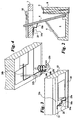
- Fig. 1 is for each of the three main current paths of a three-pole circuit breaker an electromagnetic short-circuit release 4 is provided.
- the of A tension spring 5 acted upon magnet armature 6 is at rest - that is, when no short-circuit current flows through the main flow path - on one for all Main circuits responsible, sliding adjustment 7 for adjustment of the tripping current.
- a magnetic yoke 8 is one of the associated Main current path arranged arranged current winding 2.
- the magnet armature 6 is in the case of short circuit against the force of the tension spring 5 of the attracted by the short-circuit current magnetic yoke 8 tightened.
- the dressed Magnetic armature 6 acts on a responsible for all main circuits, mechanical transmission element 10.
- the armature 6 is as in Magnetic yoke 8 mounted hinged armature executed. Between each magnet armature 6 and the adjusting element 7 is connected to signal terminals 11, 12 Contact element 14 is formed by the attractive magnet armature 6 is convertible from the open to the closed state.
- the signal connections 11, 12 lead via provided in the adjusting element 7 conductor tracks 15, 16 to all three contact elements 14, connected in parallel therewith are.
- a blocking signal is present at the signal terminals 11, 12 to remove that for the purpose of a selective release to the actuating mechanism or the triggering system of an upstream circuit breaker to be led.
- FIGS. 2 and 3 show an embodiment of a contact element 14a a spring contact 18a.
- the biased spring contact 18a is behind a fixed on the adjusting element 7 snap hook 20.
- Flat Fixed contacts 22a and 23a that is, generates the closed contact element 14a a blocking signal.
- the magnet armature 8 in the in Fig. 2 shown rest position, then the spring contact 18a under the action the tension spring 5 is lifted off the fixed contact 23a, i.e., the closed one Contact element 14a does not output a blocking signal.
- Fig. 4 shows another embodiment of a contact element 14 b with a pin-shaped configuration of the fixed contacts 22b and 23b and with a as preloaded torsion spring designed spring contact 18b, with its spiral End 25b is fixed to the one fixed contact 23b.
- the hooked other stands End 24b of the biased spring contact 18b with the other fixed contact 22b in a conductive connection.
- the hook-shaped end 24b is replaced by the armature of the Fixed contact 22b lifted.
Landscapes
- Breakers (AREA)
Claims (6)
- Agencement de disjoncteurs de protection montés les uns derrière les autres, échelonnés de manière sélective, avec déclenchement sélectif,caractérisé en ce quecomprenant un mécanisme d'actionnement contenant un dispositif de verrouillage,un disjoncteur de protection affecté directement par un court-circuit délivrant un signal de blocage au mécanisme d'actionnement ou au système de déclenchement du disjoncteur de protection monté avant,pour chaque trajet de courant principal, un déclencheur de court-circuit électromagnétique (4) est prévu, dont l'armature d'aimant (6) sollicitée par ressort s'applique dans la position de repos contre un élément d'ajustement (7) efficace pour tous les trajets de courant principal pour l'ajustement du courant de déclenchement et est attiré par une culasse d'aimant (8) parcourue par un courant dans le cas d'un court-circuit, et en l'occurrence sollicite le dispositif de verrouillage par le biais d'un élément de transfert (10) mécanique efficace pour tous les trajets de courant principal pour déclencher le mécanisme d'actionnement, etun élément de contact (14 ; 14a ; 14b) connecté à des raccords de signal (11, 12) pour délivrer un signal de blocage est réalisé entre chaque armature d'aimant (6) et l'élément d'ajustement (7) et peut être transféré de l'état ouvert dans l'état fermé par l'attraction de l'armature d'aimant (6).
- Agencement selon la revendication 1, caractérisé en ce que l'élément de contact (14a ; 14b) est équipé d'un contact à ressort (18a ; 18b).
- Agencement selon la revendication 2, caractérisé en ce que l'élément de contact (14) est un minirupteur courant dans le commerce.
- Agencement selon la revendication 2, caractérisé en ce que l'élément de contact (14a ; 14b) se compose de deux contacts fixes (22a, 23a ; 22b ; 23b) fixés sur l'élément d'ajustement (7) et du contact à ressort précontraint mécaniquement (18a ; 18b), qui est maintenu dans la position ouverte à l'encontre de sa précontrainte par l'armature magnétique (6) se trouvant dans la position de repos et dont la fermeture est autorisée par l'effet de sa précontrainte par l'attraction de l'armature magnétique (6).
- Agencement selon la revendication 1, caractérisé en ce que l'élément de contact (14) est équipé d'un contact glissant.
- Agencement selon l'une quelconque des revendications précédentes, caractérisé en ce que les éléments de contact (14 ; 14a ; 14b) associés à différents trajets de courant principal sont montés en parallèle.
Applications Claiming Priority (2)
| Application Number | Priority Date | Filing Date | Title |
|---|---|---|---|
| DE2001109950 DE10109950A1 (de) | 2001-03-01 | 2001-03-01 | Anordnung zur selektiven Auslösung |
| DE10109950 | 2001-03-01 |
Publications (3)
| Publication Number | Publication Date |
|---|---|
| EP1237172A2 EP1237172A2 (fr) | 2002-09-04 |
| EP1237172A3 EP1237172A3 (fr) | 2004-03-17 |
| EP1237172B1 true EP1237172B1 (fr) | 2005-09-14 |
Family
ID=7675982
Family Applications (1)
| Application Number | Title | Priority Date | Filing Date |
|---|---|---|---|
| EP20020003396 Expired - Lifetime EP1237172B1 (fr) | 2001-03-01 | 2002-02-14 | Dispositif pour déclenchement sélectif |
Country Status (2)
| Country | Link |
|---|---|
| EP (1) | EP1237172B1 (fr) |
| DE (2) | DE10109950A1 (fr) |
Families Citing this family (1)
| Publication number | Priority date | Publication date | Assignee | Title |
|---|---|---|---|---|
| ITMI20081092A1 (it) * | 2008-06-17 | 2009-12-18 | Gewiss Spa | Dispositivo di controllo per apparecchiature di riarmo automatico |
Family Cites Families (4)
| Publication number | Priority date | Publication date | Assignee | Title |
|---|---|---|---|---|
| DE1087680B (de) * | 1958-02-04 | 1960-08-25 | Elektroschaltgeraete Goerlitz | Elektromagnetischer UEberstromausloeser |
| DD106745A1 (fr) * | 1973-07-13 | 1974-06-20 | ||
| US5301083A (en) * | 1991-09-30 | 1994-04-05 | Eaton Corporation | Remote control residential circuit breaker |
| DE19930089A1 (de) * | 1999-06-30 | 2001-01-04 | Moeller Gmbh | Anordnung zur selektiven Auslösung |
-
2001
- 2001-03-01 DE DE2001109950 patent/DE10109950A1/de not_active Withdrawn
-
2002
- 2002-02-14 EP EP20020003396 patent/EP1237172B1/fr not_active Expired - Lifetime
- 2002-02-14 DE DE50204214T patent/DE50204214D1/de not_active Expired - Lifetime
Also Published As
| Publication number | Publication date |
|---|---|
| DE10109950A1 (de) | 2002-09-05 |
| EP1237172A3 (fr) | 2004-03-17 |
| DE50204214D1 (de) | 2005-10-20 |
| EP1237172A2 (fr) | 2002-09-04 |
Similar Documents
| Publication | Publication Date | Title |
|---|---|---|
| DE69401971T2 (de) | Magnetothermische Auslöseeinheit | |
| DE2808602A1 (de) | Schaltvorrichtung mit antiprellverklinkung | |
| WO2000079664A1 (fr) | Dispositif de coupure electrique pour la protection contre les surintensites | |
| DE69931226T2 (de) | Auslösevorrichtung für Schutzschalter | |
| DE2940706A1 (de) | Ueberstromselbstschalter mit elektromagnetischer ausloeseeinrichtung | |
| DE102008026813B4 (de) | Elektrischer selektiver Selbstschalter | |
| EP1237172B1 (fr) | Dispositif pour déclenchement sélectif | |
| EP1266388A1 (fr) | Unite de declenchement selectif pour disjoncteur | |
| DE2854637C2 (de) | Als Gruppenschutzschalter dienendes elektrisches Installationsschaltgerät | |
| EP1587125B1 (fr) | Dispositif de commutation d'installation électrique | |
| EP1065690A2 (fr) | Déclencheur sélectif | |
| EP1237171B1 (fr) | Dispositif pour le déclenchement sélectif | |
| EP0691665A1 (fr) | Coupe-circuit automatique principal | |
| EP0043020A1 (fr) | Appareillage d'installation électrique, notamment disjoncteur automatique | |
| DE3133200A1 (de) | Leitungsschutzschalter, geeignet als vorautomat | |
| DE2751452C2 (de) | Elektrisches Schaltgerät | |
| DE69119858T2 (de) | Stromverteilungsvorrichtung für die elektrische Energie einer Verteilertafel | |
| DE2945683A1 (de) | Leitungsschalter | |
| DE102012018456A1 (de) | Bimetallanordnung für selektive Schutzschaltgeräte | |
| EP2431993B1 (fr) | Commutateur modulaire basse tension | |
| DE102008015810A1 (de) | Installationsschaltgerät | |
| DE69225127T2 (de) | Selektiver automatischer Sicherheitsschalter | |
| WO2005027170A1 (fr) | Dispositif de commutation a declenchement de courant de court-circuit et procede correspondant | |
| DE2720736A1 (de) | Hoechststrombegrenzer fuer eine elektrische schaltanlage | |
| DE2718375C2 (de) | Auslöseeinrichtung |
Legal Events
| Date | Code | Title | Description |
|---|---|---|---|
| PUAI | Public reference made under article 153(3) epc to a published international application that has entered the european phase |
Free format text: ORIGINAL CODE: 0009012 |
|
| AK | Designated contracting states |
Kind code of ref document: A2 Designated state(s): AT BE CH CY DE DK ES FI FR GB GR IE IT LI LU MC NL PT SE TR |
|
| AX | Request for extension of the european patent |
Free format text: AL;LT;LV;MK;RO;SI |
|
| PUAL | Search report despatched |
Free format text: ORIGINAL CODE: 0009013 |
|
| AK | Designated contracting states |
Kind code of ref document: A3 Designated state(s): AT BE CH CY DE DK ES FI FR GB GR IE IT LI LU MC NL PT SE TR |
|
| AX | Request for extension of the european patent |
Extension state: AL LT LV MK RO SI |
|
| 17P | Request for examination filed |
Effective date: 20040901 |
|
| AKX | Designation fees paid |
Designated state(s): DE FR IT |
|
| GRAP | Despatch of communication of intention to grant a patent |
Free format text: ORIGINAL CODE: EPIDOSNIGR1 |
|
| GRAS | Grant fee paid |
Free format text: ORIGINAL CODE: EPIDOSNIGR3 |
|
| RTI1 | Title (correction) |
Free format text: SELECTIVE TRIPPING ARRANGEMENT |
|
| GRAA | (expected) grant |
Free format text: ORIGINAL CODE: 0009210 |
|
| AK | Designated contracting states |
Kind code of ref document: B1 Designated state(s): DE FR IT |
|
| REF | Corresponds to: |
Ref document number: 50204214 Country of ref document: DE Date of ref document: 20051020 Kind code of ref document: P |
|
| ET | Fr: translation filed | ||
| PLBE | No opposition filed within time limit |
Free format text: ORIGINAL CODE: 0009261 |
|
| STAA | Information on the status of an ep patent application or granted ep patent |
Free format text: STATUS: NO OPPOSITION FILED WITHIN TIME LIMIT |
|
| 26N | No opposition filed |
Effective date: 20060615 |
|
| PGFP | Annual fee paid to national office [announced via postgrant information from national office to epo] |
Ref country code: IT Payment date: 20090223 Year of fee payment: 8 |
|
| PGFP | Annual fee paid to national office [announced via postgrant information from national office to epo] |
Ref country code: FR Payment date: 20090213 Year of fee payment: 8 |
|
| PGFP | Annual fee paid to national office [announced via postgrant information from national office to epo] |
Ref country code: DE Payment date: 20100219 Year of fee payment: 9 |
|
| REG | Reference to a national code |
Ref country code: FR Ref legal event code: ST Effective date: 20101029 |
|
| PG25 | Lapsed in a contracting state [announced via postgrant information from national office to epo] |
Ref country code: FR Free format text: LAPSE BECAUSE OF NON-PAYMENT OF DUE FEES Effective date: 20100301 |
|
| PG25 | Lapsed in a contracting state [announced via postgrant information from national office to epo] |
Ref country code: IT Free format text: LAPSE BECAUSE OF NON-PAYMENT OF DUE FEES Effective date: 20100214 |
|
| REG | Reference to a national code |
Ref country code: DE Ref legal event code: R119 Ref document number: 50204214 Country of ref document: DE Effective date: 20110901 |
|
| PG25 | Lapsed in a contracting state [announced via postgrant information from national office to epo] |
Ref country code: DE Free format text: LAPSE BECAUSE OF NON-PAYMENT OF DUE FEES Effective date: 20110901 |