EP1237171B1 - Dispositif pour le déclenchement sélectif - Google Patents
Dispositif pour le déclenchement sélectif Download PDFInfo
- Publication number
- EP1237171B1 EP1237171B1 EP20020003395 EP02003395A EP1237171B1 EP 1237171 B1 EP1237171 B1 EP 1237171B1 EP 20020003395 EP20020003395 EP 20020003395 EP 02003395 A EP02003395 A EP 02003395A EP 1237171 B1 EP1237171 B1 EP 1237171B1
- Authority
- EP
- European Patent Office
- Prior art keywords
- hinged armature
- circuit
- short
- contact
- circuit breaker
- Prior art date
- Legal status (The legal status is an assumption and is not a legal conclusion. Google has not performed a legal analysis and makes no representation as to the accuracy of the status listed.)
- Expired - Lifetime
Links
- 230000000903 blocking effect Effects 0.000 claims description 14
- 238000011144 upstream manufacturing Methods 0.000 claims description 5
- 238000011161 development Methods 0.000 description 3
- 230000018109 developmental process Effects 0.000 description 3
- 238000001514 detection method Methods 0.000 description 2
- 230000000694 effects Effects 0.000 description 2
- 230000005520 electrodynamics Effects 0.000 description 2
- 230000005540 biological transmission Effects 0.000 description 1
- 230000015572 biosynthetic process Effects 0.000 description 1
- 230000001419 dependent effect Effects 0.000 description 1
- 230000003993 interaction Effects 0.000 description 1
- 230000009347 mechanical transmission Effects 0.000 description 1
- 230000005405 multipole Effects 0.000 description 1
- 230000001960 triggered effect Effects 0.000 description 1
- 238000004804 winding Methods 0.000 description 1
Images
Classifications
-
- H—ELECTRICITY
- H01—ELECTRIC ELEMENTS
- H01H—ELECTRIC SWITCHES; RELAYS; SELECTORS; EMERGENCY PROTECTIVE DEVICES
- H01H71/00—Details of the protective switches or relays covered by groups H01H73/00 - H01H83/00
- H01H71/10—Operating or release mechanisms
- H01H71/12—Automatic release mechanisms with or without manual release
- H01H71/46—Automatic release mechanisms with or without manual release having means for operating auxiliary contacts additional to the main contacts
-
- H—ELECTRICITY
- H01—ELECTRIC ELEMENTS
- H01H—ELECTRIC SWITCHES; RELAYS; SELECTORS; EMERGENCY PROTECTIVE DEVICES
- H01H71/00—Details of the protective switches or relays covered by groups H01H73/00 - H01H83/00
- H01H71/10—Operating or release mechanisms
- H01H71/1081—Modifications for selective or back-up protection; Correlation between feeder and branch circuit breaker
Definitions
- the invention relates to an arrangement for the selective triggering of successive, selectively staggered circuit breakers, in particular of - tungsschutzschalter and circuit breaker.
- the duration of action of the bondage system is determined by a timer.
- the document EP 0 406 130 B1 shows an electromagnetically acting restraint system.
- Known arrangements for generating the blocking signal for example according to document DE 195 45 928 A1, requires means for state detection and current detection of the directly affected by the short circuit breaker, which are generally realized as a complex electronic shutter and space-consuming air coils around the main flow paths. Such arrangements are therefore not suitable for small and inexpensive circuit breakers.
- Document EP 0 455 564 B1 discloses an overpressure release for a circuit breaker which responds to an overpressure occurring in the contact space caused by arcing during the electrodynamic Contact opening arises as a result of a current flowing through the switching contacts short-circuit current.
- the circuit breaker further comprises an actuating mechanism having a latch which is unlatchable via a trip shaft by a thermally-delayed overload release or an electromagnetic short-circuit release, whereby the circuit breaker is switched to the off state via the triggering actuating mechanism.
- the overpressure trigger acts on the triggering shaft with a time delay with regard to the effect on the actuating mechanism.
- this solution is not suitable for selectively triggering small short-circuit currents where no significant arcing occurs due to electrodynamic contact opening.
- a circuit breaker in which for each main flow path, an electromagnetic short-circuit release, the spring-loaded hinged armature is attracted in the event of short circuit of a current-flowing yoke, is provided and the hinged armature rests in rest position on an adjustment for adjusting the tripping current.
- the spring-loaded hinged armature is applied to a setting element for adjusting the triggering current in the rest position and is attracted by a stromumflossenen magnetic yoke in the short circuit, and formed between the hinged armature and the yoke connected to a signal terminals for outputting the blocking signal contact element , which is convertible from the open to the closed state by the attractive hinged armature.
- the per main current path of the circuit breaker acted upon by the armature of an electromagnetic short-circuit release contact element represents a simple, without electronic means austiciande arrangement for selective release, the output signal is passed in the event of a short circuit as a blocking signal to the upstream circuit breaker.
- the signal message is very fast due to the interaction with the fast-acting short-circuit release and is independent of a contact opening or arcing in the associated contact space.
- the formation of the contact element as a make contact has the advantages that the arrangement in the non-triggering state requires no electrical energy and thus the susceptibility is limited to a minimum.
- the solution according to the invention can be integrated in any circuit breaker with one or more short-circuit releases.
- Circuit-breakers equipped with the selective tripping arrangement according to the invention can easily be combined to form modules having a plurality of main current paths.
- An advantageous development further consists in that the output elements of the individual main current paths belonging contact elements are connected in parallel to cost a common blocking signal.
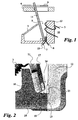
- an electromagnetic short-circuit release 10 is provided per main current path of a circuit breaker. Its acted upon by a tension spring 3 hinged armature 11 is in rest position - that is, if no short-circuit current flows through the main flow path - to a responsible for all main flow paths, displaceable adjusting element 4 for setting the tripping current.
- a magnetic yoke 12 is surrounded by a current winding 5 arranged in the associated main current path. In the event of a short circuit, the hinged armature 11 is attracted by the magnetic yoke 12 surrounded by the short-circuit current, thereby overcoming the main air gap 9.
- the tightened hinged armature 11 acts on a mechanical transmission element 6 responsible for all main current paths to the right displaced transmission element 6 in turn acts on the Verklinkungs worn an actuating mechanism of the circuit breaker, whereby the actuating mechanism triggered and thus the main flow paths are interrupted.
- the hinged armature 11 is pivotally mounted with its base 19 in a bearing point 13 of the magnetic yoke 12. At opposite points of the foot point 19 and the magnetic yoke 12, a contact element 14 is formed.
- the contact element 14 is provided with a fixed contact 15 arranged on the magnet yoke 12 and a movable contact 16 arranged at the foot point 19 of the hinged armature 11.
- the contacts 15 and 16 are connected to outgoing signal terminals 7 and 8 for receiving a blocking signal.
- the hinged armature 11 and the magnetic yoke 12 are covered with plastic parts 17 and 18, respectively, in order to achieve magnetic decoupling in this area.
- the foot point 19 of the hinged armature 11 is first attracted by the magnetic yoke 12 before the hinged armature 11 completely overcomes the main air gap 9.
- a blocking signal is output to the higher-level circuit breaker leading the triggering of the actuating mechanism.
- the contact elements 14 are connected in parallel to output a common blocking signal.
Landscapes
- Breakers (AREA)
- Refuge Islands, Traffic Blockers, Or Guard Fence (AREA)
Claims (4)
- Arrangement de disjoncteurs de protection à déclenchement sélectif branchés les uns derrière les autres et échelonnés de manière sélective,- comprenant à chaque fois un mécanisme d'actionnement contenant un dispositif d'encliquetage,- un disjoncteur de protection directement concerné par un court-circuit délivrant un signal de blocage au mécanisme d'actionnement ou au système de déclenchement du disjoncteur de protection branché en amont et- un déclencheur sur court-circuit électromagnétique (10) étant prévu dans chaque trajet de courant principal, dont l'armature mobile (11) sous contrainte d'un ressort est, en cas de court-circuit, attirée par une culasse magnétique (12) traversée par le courant,caractérisé en ce que- l'armature mobile (11) en position de repos repose contre un élément de réglage (4) destiné à régler le courant de déclenchement et- l'armature mobile (11) est munie d'un contact mobile (16) et la culasse magnétique (12) d'un contact fixe (15) pour former un élément de contact (14) relié avec des bornes de signal (7, 8) et prévu pour délivrer le signal de blocage, lequel peut être amené de la position ouverte à la position fermée par l'attraction de l'armature mobile (11).
- Arrangement selon la revendication 1, caractérisé en ce que le point d'appui (13) de l'armature mobile (11) sur la culasse magnétique (12) est équipé d'un jeu de palier pour former un entrefer variable entre la position de repos et la position attirée de l'armature mobile (11) et l'élément de contact (14) est prévu dans cette zone.
- Arrangement selon la revendication 2, caractérisé en ce que dans la zone du point d'appui (13), l'armature mobile (11) et la culasse magnétique (12) sont isolées l'une de l'autre par une matière plastique.
- Arrangement selon l'une des revendications précédentes, caractérisé en ce que les éléments de contact (14 ; 24) affectés à différents trajets de courant principaux sont branchés en parallèle.
Applications Claiming Priority (2)
| Application Number | Priority Date | Filing Date | Title |
|---|---|---|---|
| DE10109951 | 2001-03-01 | ||
| DE2001109951 DE10109951A1 (de) | 2001-03-01 | 2001-03-01 | Anordnung zur selektiven Auslösung |
Publications (3)
| Publication Number | Publication Date |
|---|---|
| EP1237171A2 EP1237171A2 (fr) | 2002-09-04 |
| EP1237171A3 EP1237171A3 (fr) | 2004-03-17 |
| EP1237171B1 true EP1237171B1 (fr) | 2006-06-07 |
Family
ID=7675983
Family Applications (1)
| Application Number | Title | Priority Date | Filing Date |
|---|---|---|---|
| EP20020003395 Expired - Lifetime EP1237171B1 (fr) | 2001-03-01 | 2002-02-14 | Dispositif pour le déclenchement sélectif |
Country Status (2)
| Country | Link |
|---|---|
| EP (1) | EP1237171B1 (fr) |
| DE (2) | DE10109951A1 (fr) |
Family Cites Families (5)
| Publication number | Priority date | Publication date | Assignee | Title |
|---|---|---|---|---|
| DE480308C (de) * | 1926-05-19 | 1929-08-13 | Aeg | UEberstromwaermeausloeser |
| DE1087680B (de) * | 1958-02-04 | 1960-08-25 | Elektroschaltgeraete Goerlitz | Elektromagnetischer UEberstromausloeser |
| DD106745A1 (fr) * | 1973-07-13 | 1974-06-20 | ||
| US5301083A (en) * | 1991-09-30 | 1994-04-05 | Eaton Corporation | Remote control residential circuit breaker |
| DE19930089A1 (de) * | 1999-06-30 | 2001-01-04 | Moeller Gmbh | Anordnung zur selektiven Auslösung |
-
2001
- 2001-03-01 DE DE2001109951 patent/DE10109951A1/de not_active Withdrawn
-
2002
- 2002-02-14 DE DE50207049T patent/DE50207049D1/de not_active Expired - Lifetime
- 2002-02-14 EP EP20020003395 patent/EP1237171B1/fr not_active Expired - Lifetime
Also Published As
| Publication number | Publication date |
|---|---|
| EP1237171A3 (fr) | 2004-03-17 |
| EP1237171A2 (fr) | 2002-09-04 |
| DE50207049D1 (de) | 2006-07-20 |
| DE10109951A1 (de) | 2002-09-05 |
Similar Documents
| Publication | Publication Date | Title |
|---|---|---|
| EP1186084B1 (fr) | Dispositif de coupure electrique pour la protection contre les surintensites | |
| DE19846639A1 (de) | Neue elektrische Schalteinrichtung | |
| DE19850397A1 (de) | Elektrische Fehlerstromschutz-Schalteinrichtung | |
| DE69206749T2 (de) | Elektrischer Schützschalter mit Einfügung von zusätzlichen Windungen im Magnetauslöser | |
| EP1237171B1 (fr) | Dispositif pour le déclenchement sélectif | |
| EP2769399B1 (fr) | Série de disjoncteurs multipolaires | |
| EP0013320B1 (fr) | Interrupteur de protection de ligne principale utilisé comme interrupteur de protection de groupe | |
| EP0691665B1 (fr) | Coupe-circuit automatique principal | |
| EP1065690A2 (fr) | Déclencheur sélectif | |
| EP1587125B1 (fr) | Dispositif de commutation d'installation électrique | |
| EP1237172B1 (fr) | Dispositif pour déclenchement sélectif | |
| DE19733268C2 (de) | Verfahren und Einrichtung zum Detektieren von Überströmen in einer Schaltanlage | |
| DE19522603A1 (de) | Schutzeinrichtung gegen Überlastung der Schaltkontakte eines Schaltgerätes | |
| EP1016112A1 (fr) | Dispositif pour obtenir une energie auxiliaire pour un systeme de declenchement, et mode d'emploi | |
| EP0043020A1 (fr) | Appareillage d'installation électrique, notamment disjoncteur automatique | |
| DE2751452C2 (de) | Elektrisches Schaltgerät | |
| DE2945683A1 (de) | Leitungsschalter | |
| DE102015217694A1 (de) | Lichtbogen-Löschvorrichtung und Schutzschaltgerät | |
| DE69119858T2 (de) | Stromverteilungsvorrichtung für die elektrische Energie einer Verteilertafel | |
| EP2431993B1 (fr) | Commutateur modulaire basse tension | |
| DE102012018456A1 (de) | Bimetallanordnung für selektive Schutzschaltgeräte | |
| DE19809205A1 (de) | Magnetsystem mit Überstromauslösung | |
| DE2720736A1 (de) | Hoechststrombegrenzer fuer eine elektrische schaltanlage | |
| DE102009059839A1 (de) | Vorrichtung zum Erkennen der Stromrichtungsumkehr | |
| DE19830017A1 (de) | Mehrpoliger strombegrenzender Leistungsschalter |
Legal Events
| Date | Code | Title | Description |
|---|---|---|---|
| PUAI | Public reference made under article 153(3) epc to a published international application that has entered the european phase |
Free format text: ORIGINAL CODE: 0009012 |
|
| AK | Designated contracting states |
Kind code of ref document: A2 Designated state(s): AT BE CH CY DE DK ES FI FR GB GR IE IT LI LU MC NL PT SE TR |
|
| AX | Request for extension of the european patent |
Free format text: AL;LT;LV;MK;RO;SI |
|
| PUAL | Search report despatched |
Free format text: ORIGINAL CODE: 0009013 |
|
| AK | Designated contracting states |
Kind code of ref document: A3 Designated state(s): AT BE CH CY DE DK ES FI FR GB GR IE IT LI LU MC NL PT SE TR |
|
| AX | Request for extension of the european patent |
Extension state: AL LT LV MK RO SI |
|
| 17P | Request for examination filed |
Effective date: 20040901 |
|
| AKX | Designation fees paid |
Designated state(s): DE FR IT |
|
| 17Q | First examination report despatched |
Effective date: 20050330 |
|
| GRAP | Despatch of communication of intention to grant a patent |
Free format text: ORIGINAL CODE: EPIDOSNIGR1 |
|
| GRAS | Grant fee paid |
Free format text: ORIGINAL CODE: EPIDOSNIGR3 |
|
| GRAA | (expected) grant |
Free format text: ORIGINAL CODE: 0009210 |
|
| AK | Designated contracting states |
Kind code of ref document: B1 Designated state(s): DE FR IT |
|
| PG25 | Lapsed in a contracting state [announced via postgrant information from national office to epo] |
Ref country code: IT Free format text: LAPSE BECAUSE OF FAILURE TO SUBMIT A TRANSLATION OF THE DESCRIPTION OR TO PAY THE FEE WITHIN THE PRESCRIBED TIME-LIMIT;WARNING: LAPSES OF ITALIAN PATENTS WITH EFFECTIVE DATE BEFORE 2007 MAY HAVE OCCURRED AT ANY TIME BEFORE 2007. THE CORRECT EFFECTIVE DATE MAY BE DIFFERENT FROM THE ONE RECORDED. Effective date: 20060607 |
|
| REF | Corresponds to: |
Ref document number: 50207049 Country of ref document: DE Date of ref document: 20060720 Kind code of ref document: P |
|
| ET | Fr: translation filed | ||
| PLBE | No opposition filed within time limit |
Free format text: ORIGINAL CODE: 0009261 |
|
| STAA | Information on the status of an ep patent application or granted ep patent |
Free format text: STATUS: NO OPPOSITION FILED WITHIN TIME LIMIT |
|
| 26N | No opposition filed |
Effective date: 20070308 |
|
| PGFP | Annual fee paid to national office [announced via postgrant information from national office to epo] |
Ref country code: IT Payment date: 20090223 Year of fee payment: 8 |
|
| PGFP | Annual fee paid to national office [announced via postgrant information from national office to epo] |
Ref country code: FR Payment date: 20090213 Year of fee payment: 8 |
|
| PGFP | Annual fee paid to national office [announced via postgrant information from national office to epo] |
Ref country code: DE Payment date: 20100219 Year of fee payment: 9 |
|
| REG | Reference to a national code |
Ref country code: FR Ref legal event code: ST Effective date: 20101029 |
|
| PG25 | Lapsed in a contracting state [announced via postgrant information from national office to epo] |
Ref country code: FR Free format text: LAPSE BECAUSE OF NON-PAYMENT OF DUE FEES Effective date: 20100301 |
|
| PG25 | Lapsed in a contracting state [announced via postgrant information from national office to epo] |
Ref country code: IT Free format text: LAPSE BECAUSE OF NON-PAYMENT OF DUE FEES Effective date: 20100214 |
|
| REG | Reference to a national code |
Ref country code: DE Ref legal event code: R119 Ref document number: 50207049 Country of ref document: DE Effective date: 20110901 |
|
| PG25 | Lapsed in a contracting state [announced via postgrant information from national office to epo] |
Ref country code: DE Free format text: LAPSE BECAUSE OF NON-PAYMENT OF DUE FEES Effective date: 20110901 |