EP1237171B1 - Selective tripping system - Google Patents
Selective tripping system Download PDFInfo
- Publication number
- EP1237171B1 EP1237171B1 EP20020003395 EP02003395A EP1237171B1 EP 1237171 B1 EP1237171 B1 EP 1237171B1 EP 20020003395 EP20020003395 EP 20020003395 EP 02003395 A EP02003395 A EP 02003395A EP 1237171 B1 EP1237171 B1 EP 1237171B1
- Authority
- EP
- European Patent Office
- Prior art keywords
- hinged armature
- circuit
- short
- contact
- circuit breaker
- Prior art date
- Legal status (The legal status is an assumption and is not a legal conclusion. Google has not performed a legal analysis and makes no representation as to the accuracy of the status listed.)
- Expired - Lifetime
Links
- 230000000903 blocking effect Effects 0.000 claims description 14
- 238000011144 upstream manufacturing Methods 0.000 claims description 5
- 238000011161 development Methods 0.000 description 3
- 230000018109 developmental process Effects 0.000 description 3
- 238000001514 detection method Methods 0.000 description 2
- 230000000694 effects Effects 0.000 description 2
- 230000005520 electrodynamics Effects 0.000 description 2
- 230000005540 biological transmission Effects 0.000 description 1
- 230000015572 biosynthetic process Effects 0.000 description 1
- 230000001419 dependent effect Effects 0.000 description 1
- 230000003993 interaction Effects 0.000 description 1
- 230000009347 mechanical transmission Effects 0.000 description 1
- 230000005405 multipole Effects 0.000 description 1
- 230000001960 triggered effect Effects 0.000 description 1
- 238000004804 winding Methods 0.000 description 1
Images
Classifications
-
- H—ELECTRICITY
- H01—ELECTRIC ELEMENTS
- H01H—ELECTRIC SWITCHES; RELAYS; SELECTORS; EMERGENCY PROTECTIVE DEVICES
- H01H71/00—Details of the protective switches or relays covered by groups H01H73/00 - H01H83/00
- H01H71/10—Operating or release mechanisms
- H01H71/12—Automatic release mechanisms with or without manual release
- H01H71/46—Automatic release mechanisms with or without manual release having means for operating auxiliary contacts additional to the main contacts
-
- H—ELECTRICITY
- H01—ELECTRIC ELEMENTS
- H01H—ELECTRIC SWITCHES; RELAYS; SELECTORS; EMERGENCY PROTECTIVE DEVICES
- H01H71/00—Details of the protective switches or relays covered by groups H01H73/00 - H01H83/00
- H01H71/10—Operating or release mechanisms
- H01H71/1081—Modifications for selective or back-up protection; Correlation between feeder and branch circuit breaker
Definitions
- the invention relates to an arrangement for the selective triggering of successive, selectively staggered circuit breakers, in particular of - tungsschutzschalter and circuit breaker.
- the duration of action of the bondage system is determined by a timer.
- the document EP 0 406 130 B1 shows an electromagnetically acting restraint system.
- Known arrangements for generating the blocking signal for example according to document DE 195 45 928 A1, requires means for state detection and current detection of the directly affected by the short circuit breaker, which are generally realized as a complex electronic shutter and space-consuming air coils around the main flow paths. Such arrangements are therefore not suitable for small and inexpensive circuit breakers.
- Document EP 0 455 564 B1 discloses an overpressure release for a circuit breaker which responds to an overpressure occurring in the contact space caused by arcing during the electrodynamic Contact opening arises as a result of a current flowing through the switching contacts short-circuit current.
- the circuit breaker further comprises an actuating mechanism having a latch which is unlatchable via a trip shaft by a thermally-delayed overload release or an electromagnetic short-circuit release, whereby the circuit breaker is switched to the off state via the triggering actuating mechanism.
- the overpressure trigger acts on the triggering shaft with a time delay with regard to the effect on the actuating mechanism.
- this solution is not suitable for selectively triggering small short-circuit currents where no significant arcing occurs due to electrodynamic contact opening.
- a circuit breaker in which for each main flow path, an electromagnetic short-circuit release, the spring-loaded hinged armature is attracted in the event of short circuit of a current-flowing yoke, is provided and the hinged armature rests in rest position on an adjustment for adjusting the tripping current.
- the spring-loaded hinged armature is applied to a setting element for adjusting the triggering current in the rest position and is attracted by a stromumflossenen magnetic yoke in the short circuit, and formed between the hinged armature and the yoke connected to a signal terminals for outputting the blocking signal contact element , which is convertible from the open to the closed state by the attractive hinged armature.
- the per main current path of the circuit breaker acted upon by the armature of an electromagnetic short-circuit release contact element represents a simple, without electronic means austiciande arrangement for selective release, the output signal is passed in the event of a short circuit as a blocking signal to the upstream circuit breaker.
- the signal message is very fast due to the interaction with the fast-acting short-circuit release and is independent of a contact opening or arcing in the associated contact space.
- the formation of the contact element as a make contact has the advantages that the arrangement in the non-triggering state requires no electrical energy and thus the susceptibility is limited to a minimum.
- the solution according to the invention can be integrated in any circuit breaker with one or more short-circuit releases.
- Circuit-breakers equipped with the selective tripping arrangement according to the invention can easily be combined to form modules having a plurality of main current paths.
- An advantageous development further consists in that the output elements of the individual main current paths belonging contact elements are connected in parallel to cost a common blocking signal.
- an electromagnetic short-circuit release 10 is provided per main current path of a circuit breaker. Its acted upon by a tension spring 3 hinged armature 11 is in rest position - that is, if no short-circuit current flows through the main flow path - to a responsible for all main flow paths, displaceable adjusting element 4 for setting the tripping current.
- a magnetic yoke 12 is surrounded by a current winding 5 arranged in the associated main current path. In the event of a short circuit, the hinged armature 11 is attracted by the magnetic yoke 12 surrounded by the short-circuit current, thereby overcoming the main air gap 9.
- the tightened hinged armature 11 acts on a mechanical transmission element 6 responsible for all main current paths to the right displaced transmission element 6 in turn acts on the Verklinkungs worn an actuating mechanism of the circuit breaker, whereby the actuating mechanism triggered and thus the main flow paths are interrupted.
- the hinged armature 11 is pivotally mounted with its base 19 in a bearing point 13 of the magnetic yoke 12. At opposite points of the foot point 19 and the magnetic yoke 12, a contact element 14 is formed.
- the contact element 14 is provided with a fixed contact 15 arranged on the magnet yoke 12 and a movable contact 16 arranged at the foot point 19 of the hinged armature 11.
- the contacts 15 and 16 are connected to outgoing signal terminals 7 and 8 for receiving a blocking signal.
- the hinged armature 11 and the magnetic yoke 12 are covered with plastic parts 17 and 18, respectively, in order to achieve magnetic decoupling in this area.
- the foot point 19 of the hinged armature 11 is first attracted by the magnetic yoke 12 before the hinged armature 11 completely overcomes the main air gap 9.
- a blocking signal is output to the higher-level circuit breaker leading the triggering of the actuating mechanism.
- the contact elements 14 are connected in parallel to output a common blocking signal.
Landscapes
- Breakers (AREA)
- Refuge Islands, Traffic Blockers, Or Guard Fence (AREA)
Description
Die Erfindung betrifft eine Anordnung zur selektiven Auslösung von hintereinander liegenden, selektiv gestaffelten Schutzschaltern, insbesondere von Lei- - tungsschutzschalter und Leistungsschalter.The invention relates to an arrangement for the selective triggering of successive, selectively staggered circuit breakers, in particular of - tungsschutzschalter and circuit breaker.
Aus der Druckschrift DE 30 20 111 A1 ist eine Anordnung von in Reihe liegenden, selektiv gestaffelten strombegrenzenden Leistungsschaltern mit je einem Schnellstauslösesystem bekannt, das im Kurzschlussfall unabhängig vom Betätigungsmechanismus schnell und damit strombegrenzend das Kontaktsystem öffnet. Die vom Kurzschluss direkt betroffenen Leistungsschalter geben ein Blockiersignal an den Betätigungsmechanismus des jeweils in Einspeiserichtung vorgeschalteten Leistungsschalters. Die Leistungsschalter besitzen ein Fesselungssystem, das die beweglichen Kontakte nach einem bestimmten Öffnungsweg kurzzeitig in der Offenstellung festhält und wieder freigibt, wenn der Betätigungsmechanismus ein Blockiersignal von einem nachgeordneten Leistungsschalter erhalten hat. Wenn das Blockiersignal ausbleibt, löst der Betätigungsmechanismus aus und überführt das Kontaktsystem in die endgültige Ausschaltstellung, wodurch gleichzeitig die Fesselung aufgehoben wird. Die Wirkdauer des Fesselungssystems wird durch ein Zeitglied bestimmt. Die Druckschrift EP 0 406 130 B1 zeigt ein elektromagnetisch wirkendes Fesselungssystem. Bekannte Anordnungen zur Erzeugung des Blockiersignals, z.B. nach Druckschrift DE 195 45 928 A1, erfordert Mittel zur Zustandserkennung und zur Stromerfassung des vom Kurzschluss direkt betroffenen Leistungsschalters, die im allgemeinen als aufwendiger elektronischer Auslöser und raumeinnehmende Luftspulen um die Hauptstrombahnen realisiert sind. Derartige Anordnungen sind daher nicht für kleine und preiswerte Schutzschalter geeignet. Die Druckschrift EP 0 455 564 B1 offenbart einen Überdruckauslöser für einen Leistungsschalter, der auf einen im Kontaktraum auftretenden Überdruck anspricht, der durch die Lichtbogenbildung bei der elektrodynamischen Kontaktöffnung infolge eines über die Schaltkontakte fließenden Kurzschlussstromes entsteht. Der Leistungsschalter umfasst weiterhin einen Betätigungsmechanismus mit einer Verklinkungseinrichtung, die über eine Auslösewelle durch einen thermisch verzögerten Überlastauslöser oder einen elektromagnetischen Kurzschlussauslöser entklinkbar ist, wodurch über den auslösenden Betätigungsmechanismus der Leistungsschalter in den Aus-Zustand überführt wird. Um eine selektive Auslösung zu gewährleisten, beaufschlagt der Überdruckauslöser die Auslösewelle hinsichtlich der Wirkung auf den Betätigungsmechanismus mit einer zeitlichen Verzögerung. Diese Lösung ist allerdings nicht zum selektiven Auslösen bei kleinen Kurzschlussströmen, bei denen keine merkliche Lichtbogenbildung infolge einer elektrodynamischen Kontaktöffnung auftritt, geeignet.From the document DE 30 20 111 A1 an arrangement of in series, selectively staggered current-limiting circuit breakers, each with a Schnellstauslösesystem is known, which opens in the event of short circuit, regardless of the operating mechanism quickly and thus current limiting the contact system. The circuit breakers directly affected by the short circuit give a blocking signal to the actuating mechanism of the circuit breaker connected upstream in the direction of feed. The circuit breakers have a restraint system that holds the movable contacts after a certain opening momentarily in the open position and releases again when the actuating mechanism has received a blocking signal from a downstream circuit breaker. If the blocking signal is absent, the actuating mechanism triggers and transfers the contact system to the final open position, which simultaneously releases the bondage. The duration of action of the bondage system is determined by a timer. The document EP 0 406 130 B1 shows an electromagnetically acting restraint system. Known arrangements for generating the blocking signal, for example according to document DE 195 45 928 A1, requires means for state detection and current detection of the directly affected by the short circuit breaker, which are generally realized as a complex electronic shutter and space-consuming air coils around the main flow paths. Such arrangements are therefore not suitable for small and inexpensive circuit breakers. Document EP 0 455 564 B1 discloses an overpressure release for a circuit breaker which responds to an overpressure occurring in the contact space caused by arcing during the electrodynamic Contact opening arises as a result of a current flowing through the switching contacts short-circuit current. The circuit breaker further comprises an actuating mechanism having a latch which is unlatchable via a trip shaft by a thermally-delayed overload release or an electromagnetic short-circuit release, whereby the circuit breaker is switched to the off state via the triggering actuating mechanism. In order to ensure selective triggering, the overpressure trigger acts on the triggering shaft with a time delay with regard to the effect on the actuating mechanism. However, this solution is not suitable for selectively triggering small short-circuit currents where no significant arcing occurs due to electrodynamic contact opening.
In einer aus EP 1 065 690 A2 bekannten gattungsgemäßen Anordnung zur selektiven Auslösung von hintereinander geschalteten, selektiv gestaffelten Schutzschaltern, in der ein vom Kurzschluss direkt betroffener Schutzschalter ein Blockiersignal an den Betätigungsmechanismus bzw. das Auslösesystem des vorgeschalteten Schutzschalters ausgibt, ist mit jeder Hauptstrombahn eines nachgeschalteten Schutzschalters ein Schutzrohrkontakt magnetisch gekoppelt und elektrisch mit dem Auslösesystem des vorgeordneten Schutzschalters verbunden. Nach DE 1 087 680 B ist ein Schutzschalter bekannt, bei dem für jede Hauptstrombahn ein elektromagnetischer Kurzschlussauslöser, dessen federbeaufschlagter Klappanker im Kurzschlussfall von einem stromumflossenen Magnetjoch angezogen wird, vorgesehen ist und der Klappanker in Ruhelage an einem Einstellelement zur Einstellung des Auslösestromes anliegt.In a generic arrangement known from EP 1 065 690 A2 for the selective triggering of series-connected selectively staggered circuit breakers, in which a circuit breaker directly affected by the circuit breaker outputs a blocking signal to the actuating mechanism or the tripping system of the upstream circuit breaker, with each main circuit connected downstream Circuit breaker a thermowell contact magnetically coupled and electrically connected to the triggering system of the upstream circuit breaker. According to DE 1 087 680 B, a circuit breaker is known, in which for each main flow path, an electromagnetic short-circuit release, the spring-loaded hinged armature is attracted in the event of short circuit of a current-flowing yoke, is provided and the hinged armature rests in rest position on an adjustment for adjusting the tripping current.
Daraus ergibt sich als Aufgabe, die selektive Auslösung mit vertretbarem Aufwand und unabhängig von Vorgängen im Kontaktraum durchzuführen.It follows as an object to perform the selective triggering with reasonable effort and independent of operations in the contact area.
Ausgehend von einer Anordnung der eingangs genannten Art wird die Aufgabe erfindungsgemäß durch die kennzeichnenden Merkmale des unabhängigen Anspruches gelöst, während den abhängigen Ansprüchen vorteilhafte Weiterbildungen der Erfindung zu entnehmen sind.Starting from an arrangement of the type mentioned, the object is achieved by the characterizing features of the independent Claim solved, while the dependent claims advantageous developments of the invention are apparent.
Es ist für jede Hauptstrombahn ein elektromagnetischer Kurzschlussauslöser vorgesehen, dessen federbeaufschlagter Klappanker in Ruhelage an einem Einstellelement zur Einstellung des Auslösestromes anliegt und im Kurzschlussfall von einem stromumflossenen Magnetjoch angezogen wird, und zwischen dem Klappanker und dem Magnetjoch ein mit Signalanschlüssen zur Ausgabe des Blockiersignals verbundenes Kontaktelement ausgebildet, das durch den anziehenden Klappanker vom geöffneten in den geschlossenen Zustand überführbar ist.It is provided for each main current path, an electromagnetic short-circuit release, the spring-loaded hinged armature is applied to a setting element for adjusting the triggering current in the rest position and is attracted by a stromumflossenen magnetic yoke in the short circuit, and formed between the hinged armature and the yoke connected to a signal terminals for outputting the blocking signal contact element , which is convertible from the open to the closed state by the attractive hinged armature.
Das pro Hauptstrombahn des Schutzschalters vom Magnetanker eines elektromagnetischen Kurzschlussauslösers beaufschlagte Kontaktelement stellt eine einfache, ohne elektronische Mittel auskommende Anordnung zur selektiven Auslösung dar, deren Ausgangssignal im Falle eines Kurzschlusses als Blockiersignal an den vorgeschalteten Schutzschalter weitergegeben wird. Die Signalmeldung erfolgt durch die Interaktion mit dem schnellauslösenden Kurzschlussauslöser sehr schnell und ist unabhängig von einer Kontaktöffnung oder einer Lichtbogenbildung im zugehörigen Kontaktraum. Die Ausbildung des Kontaktelementes als Schließerkontakt hat die Vorteile, dass die Anordnung im nicht auslösendem Zustand keine elektrische Energie erfordert und damit die Störanfälligkeit auf ein Mindestmaß beschränkt ist. Die erfindungsgemäße Lösung lässt sich in jeden Schutzschalter mit einem oder mehreren Kurzschlussauslösern integrieren. Eine gesonderte Justierung der Anordnung ist nicht erforderlich, da jeder Kurzschlussauslöser selbst über das Einstellelement einstellbar und die Funktion der Anordnung daran gekoppelt ist. Mit der erfindungsgemäßen Anordnung zur selektiven Auslösung ausgestattete Schutzschalter lassen sich ohne weiteres zu Modulen mit mehreren Hauptstrombahnen kombinieren.The per main current path of the circuit breaker acted upon by the armature of an electromagnetic short-circuit release contact element represents a simple, without electronic means auskommende arrangement for selective release, the output signal is passed in the event of a short circuit as a blocking signal to the upstream circuit breaker. The signal message is very fast due to the interaction with the fast-acting short-circuit release and is independent of a contact opening or arcing in the associated contact space. The formation of the contact element as a make contact has the advantages that the arrangement in the non-triggering state requires no electrical energy and thus the susceptibility is limited to a minimum. The solution according to the invention can be integrated in any circuit breaker with one or more short-circuit releases. A separate adjustment of the arrangement is not required, since each short-circuit release itself adjustable over the adjustment and the function of the arrangement is coupled thereto. Circuit-breakers equipped with the selective tripping arrangement according to the invention can easily be combined to form modules having a plurality of main current paths.
Eine vorteilhafte Weiterbildung besteht darin, dass die Lagerstelle des Klappankers an dem Magnetjoch mit einem Lagerspiel zur Ausbildung eines zwischen Ruhelage und angezogener Lage des Klappankers veränderlichen Luftspaltes ausgestattet und in diesem Bereich das Kontaktelement vorgesehen ist. Hierdurch wird erreicht, dass im Kurzschlussfall vor dem vollständigen Anziehen des Klappankers an das Magnetjoch durch Überwindung des Lagerspiels voreilend das Kontaktelement geschlossen und damit ein Blockiersignal ausgeben wird. Zur Verbesserung dieses Effektes ist eine magnetische Entkopplung zwischen Klappanker und Magnetjoch im Bereich der Lagerstelle durch geeignet angeordnete Kunststoffteile von Vorteil.An advantageous development is that the bearing point of the hinged armature on the magnetic yoke with a bearing clearance to form a equipped between the rest position and tightened position of the hinged armature variable air gap and in this area the contact element is provided. This ensures that in the event of a short circuit before the complete tightening of the hinged armature to the magnetic yoke by overcoming the bearing clearance leading the contact element closed and thus output a blocking signal. To improve this effect, a magnetic decoupling between hinged armature and magnetic yoke in the storage area by suitably arranged plastic parts of advantage.
Eine vorteilhafte Weiterbildung besteht weiterhin darin, dass zur Ausgabe eines gemeinsamen Blockiersignals die den einzelnen Hauptstrombahnen gehörenden Kontaktelemente kostengünstig parallel geschaltet sind.An advantageous development further consists in that the output elements of the individual main current paths belonging contact elements are connected in parallel to cost a common blocking signal.
Weitere Einzelheiten und Vorteile der Erfindung ergeben sich aus den folgenden, anhand von Figuren erläuterten Ausführungsbeispielen. Es zeigen
- Figur 1:
- eine schematische Darstellung einer Ausführungsform der Erfindung in Seitenansicht;
- Figur 2:
- eine Detaildarstellung einer Einzelheit aus der Ausführungsform gemäß Fig. 1 in Seitenansicht;
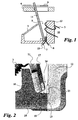
- FIG. 1:
- a schematic representation of an embodiment of the invention in side view;
- FIG. 2:
- a detailed representation of a detail of the embodiment of Figure 1 in side view.
In der Ausführungsform nach Fig. 1 und Fig. 2 ist pro Hauptstrombahn eines Schutzschalters ein elektromagnetischer Kurzschlussauslöser 10 vorgesehen. Dessen von einer Zugfeder 3 beaufschlagte Klappanker 11 liegt in Ruhelage - d.h., wenn kein Kurzschlussstrom durch die Hauptstrombahn fließt - an einem für alle Hauptstrombahnen zuständigen, verschiebbaren Einstellelement 4 zur Einstellung des Auslösestromes an. Ein Magnetjoch 12 wird von einer in der zugehörigen Hauptstrombahn angeordneten Stromwicklung 5 umgeben. Der Klappanker 11 wird im Kurzschlussfall entgegen der Kraftwirkung der Zugfeder 3 von dem vom Kurzschlussstrom umflossenen Magnetjoch 12 angezogen und überwindet dabei den Hauptluftspalt 9. Der angezogene Klappanker 11 beaufschlagt dabei ein für alle Hauptstrombahnen zuständiges, mechanisches Übertragungselement 6. Das im Kurzschlussfall gemäß Fig. 1 nach rechts verschobene Übertragungselement 6 beaufschlagt seinerseits die Verklinkungseinrichtung eines Betätigungsmechanismus des Schutzschalters, wodurch der Betätigungsmechanismus ausgelöst und damit die Hauptstrombahnen unterbrochen werden. Der Klappanker 11 ist mit seinem Fußpunkt 19 in einer Lagerstelle 13 des Magnetjochs 12 schwenkbar gelagert. An gegenüber stehenden Stellen des Fußpunktes 19 und des Magnetjochs 12 ist ein Kontaktelement 14 ausgebildet. Das Kontaktelement 14 ist mit einem am Magnetjoch 12 angeordneten feststehenden Kontakt 15 und einem am Fußpunkt 19 des Klappankers 11 angeordneten beweglichen Kontakt 16 versehen. Die Kontakte 15 und 16 sind mit nach außen führenden Signalanschlüssen 7 und 8 zur Abnahme eines Blockiersignals verbunden. Im Bereich der Lagerstelle 13 sind der Klappanker 11 und das Magnetjoch 12 mit Kunststoffteilen 17 bzw. 18 abgedeckt, um in diesem Gebiet eine magnetische Entkopplung zu erzielen. Beim Auftreten eines Kurzschlussstromes durch die zugehörige Hauptstrombahn wird zuerst der Fußpunkt 19 des Klappankers 11 vom Magnetjoch 12 angezogen, ehe der Klappanker 11 vollständig den Hauptluftspalt 9 überwindet. Damit wird voreilend vor der Auslösung des Betätigungsmechanismus ein Blockiersignal an den übergeordneten Schutzschalter ausgegeben. Bei Verwendung eines mehrpoligen Schutzschalters sind ebenso viele Kurzschlussauslöser 10 vorhanden, deren Kontaktelemente 14 zur Ausgabe eines gemeinsamen Blockiersignals parallel zu schalten sind.In the embodiment according to FIGS. 1 and 2, an electromagnetic short-
Claims (4)
- Arrangement of series-connected, selectively staggered circuit breakers with selective tripping- each having an actuating mechanism containing a latching device,- a circuit breaker which is directly affected by the short circuit outputting a blocking signal to the actuating mechanism or to the tripping system of the upstream circuit breaker, and- an electromagnetic short-circuit release (10) being provided for each main current path, the spring-loaded hinged armature (11) of said short-circuit release (10) being attracted by a magnet yoke (12), around which current flows, in the event of a short circuit,characterized in that- in the rest position, the hinged armature (11) bears against an adjusting element (4) for the purpose of adjusting the tripping current, and- the hinged armature (11) is provided with a movable contact (16), and the magnet yoke (12) is provided with a fixed contact (15) so as to form a contact element (14), which is connected to signal connections (7, 8), is provided for the purpose of outputting the blocking signal and can be moved from the open state to the closed state by the attracting hinged armature (11).
- Arrangement according to Claim 1, characterized in that the bearing point (13) of the hinged armature (11) on the magnet yoke (12) is provided with bearing play so as to form an air gap which can be altered between the rest position and the attracted position of the hinged armature (11), and the contact element (14) is provided in this region.
- Arrangement according to Claim 2, characterized in that, in the region of the bearing point (13), the hinged armature (11) and the magnet yoke (12) are insulated from one another by means of plastic.
- Arrangement according to one of the preceding claims, characterized in that the contact elements (14; 24) associated with various main current paths are connected in parallel.
Applications Claiming Priority (2)
| Application Number | Priority Date | Filing Date | Title |
|---|---|---|---|
| DE10109951 | 2001-03-01 | ||
| DE2001109951 DE10109951A1 (en) | 2001-03-01 | 2001-03-01 | Selective trip arrangement |
Publications (3)
| Publication Number | Publication Date |
|---|---|
| EP1237171A2 EP1237171A2 (en) | 2002-09-04 |
| EP1237171A3 EP1237171A3 (en) | 2004-03-17 |
| EP1237171B1 true EP1237171B1 (en) | 2006-06-07 |
Family
ID=7675983
Family Applications (1)
| Application Number | Title | Priority Date | Filing Date |
|---|---|---|---|
| EP20020003395 Expired - Lifetime EP1237171B1 (en) | 2001-03-01 | 2002-02-14 | Selective tripping system |
Country Status (2)
| Country | Link |
|---|---|
| EP (1) | EP1237171B1 (en) |
| DE (2) | DE10109951A1 (en) |
Family Cites Families (5)
| Publication number | Priority date | Publication date | Assignee | Title |
|---|---|---|---|---|
| DE480308C (en) * | 1926-05-19 | 1929-08-13 | Aeg | Overcurrent heat release |
| DE1087680B (en) * | 1958-02-04 | 1960-08-25 | Elektroschaltgeraete Goerlitz | Electromagnetic overcurrent release |
| DD106745A1 (en) * | 1973-07-13 | 1974-06-20 | ||
| US5301083A (en) * | 1991-09-30 | 1994-04-05 | Eaton Corporation | Remote control residential circuit breaker |
| DE19930089A1 (en) * | 1999-06-30 | 2001-01-04 | Moeller Gmbh | Selective trip arrangement |
-
2001
- 2001-03-01 DE DE2001109951 patent/DE10109951A1/en not_active Withdrawn
-
2002
- 2002-02-14 DE DE50207049T patent/DE50207049D1/en not_active Expired - Lifetime
- 2002-02-14 EP EP20020003395 patent/EP1237171B1/en not_active Expired - Lifetime
Also Published As
| Publication number | Publication date |
|---|---|
| EP1237171A3 (en) | 2004-03-17 |
| EP1237171A2 (en) | 2002-09-04 |
| DE50207049D1 (en) | 2006-07-20 |
| DE10109951A1 (en) | 2002-09-05 |
Similar Documents
| Publication | Publication Date | Title |
|---|---|---|
| EP1186084B1 (en) | Electrical circuit breaker for protecting against overcurrents | |
| DE19846639A1 (en) | Electrical switching device for protective switchgear has micro-relay cells connected in series and parallel, and integrated in chip | |
| DE19850397A1 (en) | Electrical residual current circuit breaker | |
| DE69206749T2 (en) | Electrical contactor switch with insertion of additional turns in the magnetic release | |
| EP1237171B1 (en) | Selective tripping system | |
| EP2769399B1 (en) | Range of multi-pole circuit breakers | |
| EP0013320B1 (en) | Electrical main line protection switch serving as group protection switch | |
| EP0691665B1 (en) | Main cut-out | |
| EP1065690A2 (en) | Selective tripping device | |
| EP1587125B1 (en) | Installation switchgear | |
| EP1237172B1 (en) | Selective tripping arrangement | |
| DE19733268C2 (en) | Method and device for detecting overcurrents in a switchgear | |
| DE19522603A1 (en) | Protective device against overloading the switching contacts of a switching device | |
| EP1016112A1 (en) | Device for generating auxiliary energy for a trigger system, and operating mode | |
| EP0043020A1 (en) | Electric installation device, especially automatic switch | |
| DE2751452C2 (en) | Electrical switchgear | |
| DE2945683A1 (en) | Combined temp. and overload operated switch - has magnetic and temp. operated release in parallel with magnetic release with arcing plates | |
| DE102015217694A1 (en) | Arc extinguishing device and protective switching device | |
| DE69119858T2 (en) | Power distribution device for the electrical energy of a distribution panel | |
| EP2431993B1 (en) | Modular low voltage switch | |
| DE102012018456A1 (en) | Bimetallic arrangement for e.g. main circuit breaker, has thermal bimetallic strip including strip portions that are controlled depending upon incident by overload current or residual current, for selective behavior of switching device | |
| DE19809205A1 (en) | Magnetic system with over current release esp. contactor | |
| DE2720736A1 (en) | HIGH CURRENT LIMITER FOR AN ELECTRICAL SWITCHGEAR | |
| DE102009059839A1 (en) | Device for use with e.g. electrical switching device for detecting reversal of current direction in photovoltaic strand, has magnetically polarized armature operatively connected with actuator | |
| DE19830017A1 (en) | Over-current trigger for multi-pole power switch |
Legal Events
| Date | Code | Title | Description |
|---|---|---|---|
| PUAI | Public reference made under article 153(3) epc to a published international application that has entered the european phase |
Free format text: ORIGINAL CODE: 0009012 |
|
| AK | Designated contracting states |
Kind code of ref document: A2 Designated state(s): AT BE CH CY DE DK ES FI FR GB GR IE IT LI LU MC NL PT SE TR |
|
| AX | Request for extension of the european patent |
Free format text: AL;LT;LV;MK;RO;SI |
|
| PUAL | Search report despatched |
Free format text: ORIGINAL CODE: 0009013 |
|
| AK | Designated contracting states |
Kind code of ref document: A3 Designated state(s): AT BE CH CY DE DK ES FI FR GB GR IE IT LI LU MC NL PT SE TR |
|
| AX | Request for extension of the european patent |
Extension state: AL LT LV MK RO SI |
|
| 17P | Request for examination filed |
Effective date: 20040901 |
|
| AKX | Designation fees paid |
Designated state(s): DE FR IT |
|
| 17Q | First examination report despatched |
Effective date: 20050330 |
|
| GRAP | Despatch of communication of intention to grant a patent |
Free format text: ORIGINAL CODE: EPIDOSNIGR1 |
|
| GRAS | Grant fee paid |
Free format text: ORIGINAL CODE: EPIDOSNIGR3 |
|
| GRAA | (expected) grant |
Free format text: ORIGINAL CODE: 0009210 |
|
| AK | Designated contracting states |
Kind code of ref document: B1 Designated state(s): DE FR IT |
|
| PG25 | Lapsed in a contracting state [announced via postgrant information from national office to epo] |
Ref country code: IT Free format text: LAPSE BECAUSE OF FAILURE TO SUBMIT A TRANSLATION OF THE DESCRIPTION OR TO PAY THE FEE WITHIN THE PRESCRIBED TIME-LIMIT;WARNING: LAPSES OF ITALIAN PATENTS WITH EFFECTIVE DATE BEFORE 2007 MAY HAVE OCCURRED AT ANY TIME BEFORE 2007. THE CORRECT EFFECTIVE DATE MAY BE DIFFERENT FROM THE ONE RECORDED. Effective date: 20060607 |
|
| REF | Corresponds to: |
Ref document number: 50207049 Country of ref document: DE Date of ref document: 20060720 Kind code of ref document: P |
|
| ET | Fr: translation filed | ||
| PLBE | No opposition filed within time limit |
Free format text: ORIGINAL CODE: 0009261 |
|
| STAA | Information on the status of an ep patent application or granted ep patent |
Free format text: STATUS: NO OPPOSITION FILED WITHIN TIME LIMIT |
|
| 26N | No opposition filed |
Effective date: 20070308 |
|
| PGFP | Annual fee paid to national office [announced via postgrant information from national office to epo] |
Ref country code: IT Payment date: 20090223 Year of fee payment: 8 |
|
| PGFP | Annual fee paid to national office [announced via postgrant information from national office to epo] |
Ref country code: FR Payment date: 20090213 Year of fee payment: 8 |
|
| PGFP | Annual fee paid to national office [announced via postgrant information from national office to epo] |
Ref country code: DE Payment date: 20100219 Year of fee payment: 9 |
|
| REG | Reference to a national code |
Ref country code: FR Ref legal event code: ST Effective date: 20101029 |
|
| PG25 | Lapsed in a contracting state [announced via postgrant information from national office to epo] |
Ref country code: FR Free format text: LAPSE BECAUSE OF NON-PAYMENT OF DUE FEES Effective date: 20100301 |
|
| PG25 | Lapsed in a contracting state [announced via postgrant information from national office to epo] |
Ref country code: IT Free format text: LAPSE BECAUSE OF NON-PAYMENT OF DUE FEES Effective date: 20100214 |
|
| REG | Reference to a national code |
Ref country code: DE Ref legal event code: R119 Ref document number: 50207049 Country of ref document: DE Effective date: 20110901 |
|
| PG25 | Lapsed in a contracting state [announced via postgrant information from national office to epo] |
Ref country code: DE Free format text: LAPSE BECAUSE OF NON-PAYMENT OF DUE FEES Effective date: 20110901 |