EP1237172A2 - Dispositif pour déclenchement sélectif - Google Patents
Dispositif pour déclenchement sélectif Download PDFInfo
- Publication number
- EP1237172A2 EP1237172A2 EP02003396A EP02003396A EP1237172A2 EP 1237172 A2 EP1237172 A2 EP 1237172A2 EP 02003396 A EP02003396 A EP 02003396A EP 02003396 A EP02003396 A EP 02003396A EP 1237172 A2 EP1237172 A2 EP 1237172A2
- Authority
- EP
- European Patent Office
- Prior art keywords
- contact
- circuit
- magnet armature
- short
- arrangement according
- Prior art date
- Legal status (The legal status is an assumption and is not a legal conclusion. Google has not performed a legal analysis and makes no representation as to the accuracy of the status listed.)
- Granted
Links
Images

Classifications
-
- H—ELECTRICITY
- H01—ELECTRIC ELEMENTS
- H01H—ELECTRIC SWITCHES; RELAYS; SELECTORS; EMERGENCY PROTECTIVE DEVICES
- H01H71/00—Details of the protective switches or relays covered by groups H01H73/00 - H01H83/00
- H01H71/10—Operating or release mechanisms
- H01H71/1081—Modifications for selective or back-up protection; Correlation between feeder and branch circuit breaker
-
- H—ELECTRICITY
- H01—ELECTRIC ELEMENTS
- H01H—ELECTRIC SWITCHES; RELAYS; SELECTORS; EMERGENCY PROTECTIVE DEVICES
- H01H71/00—Details of the protective switches or relays covered by groups H01H73/00 - H01H83/00
- H01H71/10—Operating or release mechanisms
- H01H71/12—Automatic release mechanisms with or without manual release
- H01H71/46—Automatic release mechanisms with or without manual release having means for operating auxiliary contacts additional to the main contacts
Definitions
- the invention relates to an arrangement for selective triggering from one another horizontal, selectively staggered circuit breakers, especially circuit breakers and circuit breakers.
- the duration of action of the restraint system is determined by a timer.
- the Document EP 0 406 130 B1 shows an electromagnetic restraining system.
- Known arrangements for generating the blocking signal e.g. according to document DE 195 45 928 A1, requires means for status detection and for current detection of the circuit breaker directly affected by the short circuit, which in general as a complex electronic trigger and space-taking air coils around the main current paths are realized. Such Arrangements are therefore not for small and inexpensive circuit breakers suitable.
- EP 0 455 564 B1 discloses an overpressure release for a circuit breaker that detects an overpressure in the contact space appeals to the electric arcing in the electrodynamic Contact opening due to a short-circuit current flowing across the switch contacts arises.
- the circuit breaker further includes an operating mechanism with a latching device that has a release shaft by a thermally delayed overload release or an electromagnetic Short-circuit release can be released, which means that the trigger Operating mechanism of the circuit breaker transferred to the off state becomes.
- the overpressure release is activated to ensure selective triggering the trigger shaft with regard to the effect on the actuating mechanism with a time delay.
- this solution is not for selective tripping at small short-circuit currents where no noticeable arcing due to an electrodynamic contact opening occurs, suitable.
- That per main circuit of the circuit breaker from the magnet armature of an electromagnetic Short-circuit release actuated contact element provides a simple arrangement without selective electronic means Trip represents the output signal in the event of a short circuit as Blocking signal is passed to the upstream circuit breaker.
- the Signaling occurs through the interaction with the quick-release short-circuit release very fast and is independent of a contact opening or arcing in the associated contact space.
- Training The contact element as a normally open contact has the advantages that the arrangement does not require electrical energy in the non-triggering state and so that the susceptibility to interference is kept to a minimum.
- the invention Solution can be found in any circuit breaker with one or more Integrate short-circuit releases. A separate adjustment of the arrangement is not necessary as each short-circuit release itself via the setting element adjustable and the function of the arrangement is coupled to it. With the inventive arrangement equipped for selective triggering Circuit breakers can be easily converted into modules with several main current paths combine.
- An advantageous development of the arrangement according to the invention consists in the equipment of the contact element with a spring contact, in particular with a commercially available microswitch or with a preloaded spring contact, between two fixed contacts attached to the setting element acts.
- the contact element can also have a sliding contact be equipped.
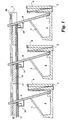
- FIG. 1 is a three-pole circuit breaker for each of the three main current paths an electromagnetic short-circuit release 4 is provided.
- the of a tension spring 5 loaded magnet armature 6 is in the rest position - i.e. when no short-circuit current flows through the main current path - one for all Main current paths responsible, adjustable adjustment element 7 for adjustment of the tripping current.
- a magnetic yoke 8 is in the associated one Main current path arranged current winding 2 surrounded.
- the magnetic anchor 6 is in the event of a short circuit against the force of the tension spring 5 of attracted by the short-circuit current magnet yoke 8.
- the dressed Magnetic armature 6 acts upon a person responsible for all main current paths mechanical transmission element 10.
- the magnet armature 6 is as in Magnetic yoke 8 mounted hinged anchor executed. Between each magnet armature 6 and the adjusting element 7 is connected to signal connections 11, 12 Contact element 14 formed by the attracting magnet armature 6 can be transferred from the open to the closed state.
- the signal connections 11, 12 lead over conductor tracks provided in the adjusting element 7 15, 16 to all three contact elements 14, which are thus connected in parallel are.
- there is a blocking signal at the signal connections 11, 12 inferred that for the purpose of selective triggering on the actuating mechanism or the trigger system of an upstream circuit breaker to be led.
- FIGS. 2 and 3 show an embodiment of a contact element 14a a spring contact 18a.
- the preloaded spring contact 18a is behind one formed on the adjusting element 7 molded snap hook 20.
- flat Fixed contacts 22a or 23a i.e., the closed contact element 14a generates a blocking signal.
- the magnet armature 8 is in the in Fig. 2 shown rest position, then the spring contact 18a under the action the tension spring 5 is lifted from the fixed contact 23a, i.e. the closed one Contact element 14a does not output a blocking signal.
- Fig. 4 shows another embodiment of a contact element 14b with a pin-shaped configuration of the fixed contacts 22b and 23b and with a biased torsion spring designed spring contact 18b, with its spiral End 25b at which a fixed contact 23b is fixed.
- I'm unaffected Condition i.e. in the event of a short circuit, the hook-shaped other stands End 24b of the preloaded spring contact 18b with the other fixed contact 22b in conductive connection.
- the present invention is not limited to the above-described embodiments limited, but also includes all within the meaning of the invention equivalent embodiments.
- the invention can be to the effect that the contact elements as commercially available Microswitches are designed or equipped with a sliding contact.
Landscapes
- Breakers (AREA)
Applications Claiming Priority (2)
| Application Number | Priority Date | Filing Date | Title |
|---|---|---|---|
| DE2001109950 DE10109950A1 (de) | 2001-03-01 | 2001-03-01 | Anordnung zur selektiven Auslösung |
| DE10109950 | 2001-03-01 |
Publications (3)
| Publication Number | Publication Date |
|---|---|
| EP1237172A2 true EP1237172A2 (fr) | 2002-09-04 |
| EP1237172A3 EP1237172A3 (fr) | 2004-03-17 |
| EP1237172B1 EP1237172B1 (fr) | 2005-09-14 |
Family
ID=7675982
Family Applications (1)
| Application Number | Title | Priority Date | Filing Date |
|---|---|---|---|
| EP20020003396 Expired - Lifetime EP1237172B1 (fr) | 2001-03-01 | 2002-02-14 | Dispositif pour déclenchement sélectif |
Country Status (2)
| Country | Link |
|---|---|
| EP (1) | EP1237172B1 (fr) |
| DE (2) | DE10109950A1 (fr) |
Cited By (1)
| Publication number | Priority date | Publication date | Assignee | Title |
|---|---|---|---|---|
| EP2136383A3 (fr) * | 2008-06-17 | 2013-06-26 | GEWISS S.p.A. | Dispositif de contrôle pour appareil de rearmement automatique |
Family Cites Families (4)
| Publication number | Priority date | Publication date | Assignee | Title |
|---|---|---|---|---|
| DE1087680B (de) * | 1958-02-04 | 1960-08-25 | Elektroschaltgeraete Goerlitz | Elektromagnetischer UEberstromausloeser |
| DD106745A1 (fr) * | 1973-07-13 | 1974-06-20 | ||
| US5301083A (en) * | 1991-09-30 | 1994-04-05 | Eaton Corporation | Remote control residential circuit breaker |
| DE19930089A1 (de) * | 1999-06-30 | 2001-01-04 | Moeller Gmbh | Anordnung zur selektiven Auslösung |
-
2001
- 2001-03-01 DE DE2001109950 patent/DE10109950A1/de not_active Withdrawn
-
2002
- 2002-02-14 EP EP20020003396 patent/EP1237172B1/fr not_active Expired - Lifetime
- 2002-02-14 DE DE50204214T patent/DE50204214D1/de not_active Expired - Lifetime
Cited By (1)
| Publication number | Priority date | Publication date | Assignee | Title |
|---|---|---|---|---|
| EP2136383A3 (fr) * | 2008-06-17 | 2013-06-26 | GEWISS S.p.A. | Dispositif de contrôle pour appareil de rearmement automatique |
Also Published As
| Publication number | Publication date |
|---|---|
| DE10109950A1 (de) | 2002-09-05 |
| EP1237172B1 (fr) | 2005-09-14 |
| EP1237172A3 (fr) | 2004-03-17 |
| DE50204214D1 (de) | 2005-10-20 |
Similar Documents
| Publication | Publication Date | Title |
|---|---|---|
| DE69401971T2 (de) | Magnetothermische Auslöseeinheit | |
| DE2808602A1 (de) | Schaltvorrichtung mit antiprellverklinkung | |
| EP1186084A1 (fr) | Dispositif de coupure electrique pour la protection contre les surintensites | |
| CH653188A5 (de) | Selektive sicherheitsschalteinrichtung zum schutz einer leistungsverteilungsanlage. | |
| EP0954873A1 (fr) | Sectionneur de coupure en charge, en particulier pour circuit de charge d'une batterie d'un vehicule a moteur | |
| WO2009114890A1 (fr) | Module de déclenchement pour un appareil de commutation | |
| DE69931226T2 (de) | Auslösevorrichtung für Schutzschalter | |
| DE10244961B3 (de) | Selektiver Leitungsschutzschalter | |
| EP1266388A1 (fr) | Unite de declenchement selectif pour disjoncteur | |
| EP2286432A1 (fr) | Commutateur automatique électrique sélectif | |
| EP1237172B1 (fr) | Dispositif pour déclenchement sélectif | |
| EP1065690A2 (fr) | Déclencheur sélectif | |
| DE102010019353B3 (de) | Leistungsschalter mit strombegrenzenden Eigenschaften | |
| DE3316230A1 (de) | Leitungs- und/oder geraeteschutzschalter gegen ueberstrom und kurzschluss | |
| EP1237171B1 (fr) | Dispositif pour le déclenchement sélectif | |
| EP0043020A1 (fr) | Appareillage d'installation électrique, notamment disjoncteur automatique | |
| DE3133200A1 (de) | Leitungsschutzschalter, geeignet als vorautomat | |
| DE69119858T2 (de) | Stromverteilungsvorrichtung für die elektrische Energie einer Verteilertafel | |
| DE19741919C1 (de) | Lasttrennschalter, insbesondere für den Laststromkreis eines Fahrzeugs | |
| DE2720736C2 (de) | Höchststrombegrenzer für eine elektrische Schaltanlage | |
| EP0827251A2 (fr) | Interrupteur électrique à basse tension | |
| EP0990247B1 (fr) | Dispositif d'enclenchement d'un discontacteur | |
| EP2680293A1 (fr) | Mécanisme de déclenchement | |
| DE2625894C2 (de) | Elektromagnetischer Überstromauslöser für elektrische Schalter | |
| EP0523420B1 (fr) | Déclencheur de court-circuit à action instantanée |
Legal Events
| Date | Code | Title | Description |
|---|---|---|---|
| PUAI | Public reference made under article 153(3) epc to a published international application that has entered the european phase |
Free format text: ORIGINAL CODE: 0009012 |
|
| AK | Designated contracting states |
Kind code of ref document: A2 Designated state(s): AT BE CH CY DE DK ES FI FR GB GR IE IT LI LU MC NL PT SE TR |
|
| AX | Request for extension of the european patent |
Free format text: AL;LT;LV;MK;RO;SI |
|
| PUAL | Search report despatched |
Free format text: ORIGINAL CODE: 0009013 |
|
| AK | Designated contracting states |
Kind code of ref document: A3 Designated state(s): AT BE CH CY DE DK ES FI FR GB GR IE IT LI LU MC NL PT SE TR |
|
| AX | Request for extension of the european patent |
Extension state: AL LT LV MK RO SI |
|
| 17P | Request for examination filed |
Effective date: 20040901 |
|
| AKX | Designation fees paid |
Designated state(s): DE FR IT |
|
| GRAP | Despatch of communication of intention to grant a patent |
Free format text: ORIGINAL CODE: EPIDOSNIGR1 |
|
| GRAS | Grant fee paid |
Free format text: ORIGINAL CODE: EPIDOSNIGR3 |
|
| RTI1 | Title (correction) |
Free format text: SELECTIVE TRIPPING ARRANGEMENT |
|
| GRAA | (expected) grant |
Free format text: ORIGINAL CODE: 0009210 |
|
| AK | Designated contracting states |
Kind code of ref document: B1 Designated state(s): DE FR IT |
|
| REF | Corresponds to: |
Ref document number: 50204214 Country of ref document: DE Date of ref document: 20051020 Kind code of ref document: P |
|
| ET | Fr: translation filed | ||
| PLBE | No opposition filed within time limit |
Free format text: ORIGINAL CODE: 0009261 |
|
| STAA | Information on the status of an ep patent application or granted ep patent |
Free format text: STATUS: NO OPPOSITION FILED WITHIN TIME LIMIT |
|
| 26N | No opposition filed |
Effective date: 20060615 |
|
| PGFP | Annual fee paid to national office [announced via postgrant information from national office to epo] |
Ref country code: IT Payment date: 20090223 Year of fee payment: 8 |
|
| PGFP | Annual fee paid to national office [announced via postgrant information from national office to epo] |
Ref country code: FR Payment date: 20090213 Year of fee payment: 8 |
|
| PGFP | Annual fee paid to national office [announced via postgrant information from national office to epo] |
Ref country code: DE Payment date: 20100219 Year of fee payment: 9 |
|
| REG | Reference to a national code |
Ref country code: FR Ref legal event code: ST Effective date: 20101029 |
|
| PG25 | Lapsed in a contracting state [announced via postgrant information from national office to epo] |
Ref country code: FR Free format text: LAPSE BECAUSE OF NON-PAYMENT OF DUE FEES Effective date: 20100301 |
|
| PG25 | Lapsed in a contracting state [announced via postgrant information from national office to epo] |
Ref country code: IT Free format text: LAPSE BECAUSE OF NON-PAYMENT OF DUE FEES Effective date: 20100214 |
|
| REG | Reference to a national code |
Ref country code: DE Ref legal event code: R119 Ref document number: 50204214 Country of ref document: DE Effective date: 20110901 |
|
| PG25 | Lapsed in a contracting state [announced via postgrant information from national office to epo] |
Ref country code: DE Free format text: LAPSE BECAUSE OF NON-PAYMENT OF DUE FEES Effective date: 20110901 |