EP1237138A1 - Dispositif afficheur d'images - Google Patents
Dispositif afficheur d'images Download PDFInfo
- Publication number
- EP1237138A1 EP1237138A1 EP00961044A EP00961044A EP1237138A1 EP 1237138 A1 EP1237138 A1 EP 1237138A1 EP 00961044 A EP00961044 A EP 00961044A EP 00961044 A EP00961044 A EP 00961044A EP 1237138 A1 EP1237138 A1 EP 1237138A1
- Authority
- EP
- European Patent Office
- Prior art keywords
- luminance
- image display
- display device
- lookup table
- multiplying
- Prior art date
- Legal status (The legal status is an assumption and is not a legal conclusion. Google has not performed a legal analysis and makes no representation as to the accuracy of the status listed.)
- Withdrawn
Links
Images


Classifications
-
- G—PHYSICS
- G02—OPTICS
- G02B—OPTICAL ELEMENTS, SYSTEMS OR APPARATUS
- G02B6/00—Light guides; Structural details of arrangements comprising light guides and other optical elements, e.g. couplings
- G02B6/0001—Light guides; Structural details of arrangements comprising light guides and other optical elements, e.g. couplings specially adapted for lighting devices or systems
- G02B6/0011—Light guides; Structural details of arrangements comprising light guides and other optical elements, e.g. couplings specially adapted for lighting devices or systems the light guides being planar or of plate-like form
- G02B6/0033—Means for improving the coupling-out of light from the light guide
- G02B6/0035—Means for improving the coupling-out of light from the light guide provided on the surface of the light guide or in the bulk of it
- G02B6/004—Scattering dots or dot-like elements, e.g. microbeads, scattering particles, nanoparticles
- G02B6/0043—Scattering dots or dot-like elements, e.g. microbeads, scattering particles, nanoparticles provided on the surface of the light guide
-
- G—PHYSICS
- G09—EDUCATION; CRYPTOGRAPHY; DISPLAY; ADVERTISING; SEALS
- G09G—ARRANGEMENTS OR CIRCUITS FOR CONTROL OF INDICATING DEVICES USING STATIC MEANS TO PRESENT VARIABLE INFORMATION
- G09G3/00—Control arrangements or circuits, of interest only in connection with visual indicators other than cathode-ray tubes
- G09G3/20—Control arrangements or circuits, of interest only in connection with visual indicators other than cathode-ray tubes for presentation of an assembly of a number of characters, e.g. a page, by composing the assembly by combination of individual elements arranged in a matrix no fixed position being assigned to or needed to be assigned to the individual characters or partial characters
- G09G3/22—Control arrangements or circuits, of interest only in connection with visual indicators other than cathode-ray tubes for presentation of an assembly of a number of characters, e.g. a page, by composing the assembly by combination of individual elements arranged in a matrix no fixed position being assigned to or needed to be assigned to the individual characters or partial characters using controlled light sources
-
- G—PHYSICS
- G02—OPTICS
- G02B—OPTICAL ELEMENTS, SYSTEMS OR APPARATUS
- G02B6/00—Light guides; Structural details of arrangements comprising light guides and other optical elements, e.g. couplings
- G02B6/0001—Light guides; Structural details of arrangements comprising light guides and other optical elements, e.g. couplings specially adapted for lighting devices or systems
- G02B6/0011—Light guides; Structural details of arrangements comprising light guides and other optical elements, e.g. couplings specially adapted for lighting devices or systems the light guides being planar or of plate-like form
- G02B6/0033—Means for improving the coupling-out of light from the light guide
- G02B6/0058—Means for improving the coupling-out of light from the light guide varying in density, size, shape or depth along the light guide
- G02B6/0061—Means for improving the coupling-out of light from the light guide varying in density, size, shape or depth along the light guide to provide homogeneous light output intensity
-
- G—PHYSICS
- G09—EDUCATION; CRYPTOGRAPHY; DISPLAY; ADVERTISING; SEALS
- G09G—ARRANGEMENTS OR CIRCUITS FOR CONTROL OF INDICATING DEVICES USING STATIC MEANS TO PRESENT VARIABLE INFORMATION
- G09G5/00—Control arrangements or circuits for visual indicators common to cathode-ray tube indicators and other visual indicators
- G09G5/10—Intensity circuits
-
- H—ELECTRICITY
- H04—ELECTRIC COMMUNICATION TECHNIQUE
- H04N—PICTORIAL COMMUNICATION, e.g. TELEVISION
- H04N5/00—Details of television systems
- H04N5/44—Receiver circuitry for the reception of television signals according to analogue transmission standards
- H04N5/57—Control of contrast or brightness
-
- H—ELECTRICITY
- H04—ELECTRIC COMMUNICATION TECHNIQUE
- H04N—PICTORIAL COMMUNICATION, e.g. TELEVISION
- H04N9/00—Details of colour television systems
- H04N9/64—Circuits for processing colour signals
- H04N9/68—Circuits for processing colour signals for controlling the amplitude of colour signals, e.g. automatic chroma control circuits
- H04N9/69—Circuits for processing colour signals for controlling the amplitude of colour signals, e.g. automatic chroma control circuits for modifying the colour signals by gamma correction
-
- G—PHYSICS
- G09—EDUCATION; CRYPTOGRAPHY; DISPLAY; ADVERTISING; SEALS
- G09G—ARRANGEMENTS OR CIRCUITS FOR CONTROL OF INDICATING DEVICES USING STATIC MEANS TO PRESENT VARIABLE INFORMATION
- G09G2320/00—Control of display operating conditions
- G09G2320/02—Improving the quality of display appearance
- G09G2320/0271—Adjustment of the gradation levels within the range of the gradation scale, e.g. by redistribution or clipping
- G09G2320/0276—Adjustment of the gradation levels within the range of the gradation scale, e.g. by redistribution or clipping for the purpose of adaptation to the characteristics of a display device, i.e. gamma correction
-
- G—PHYSICS
- G09—EDUCATION; CRYPTOGRAPHY; DISPLAY; ADVERTISING; SEALS
- G09G—ARRANGEMENTS OR CIRCUITS FOR CONTROL OF INDICATING DEVICES USING STATIC MEANS TO PRESENT VARIABLE INFORMATION
- G09G2320/00—Control of display operating conditions
- G09G2320/02—Improving the quality of display appearance
- G09G2320/0285—Improving the quality of display appearance using tables for spatial correction of display data
-
- G—PHYSICS
- G09—EDUCATION; CRYPTOGRAPHY; DISPLAY; ADVERTISING; SEALS
- G09G—ARRANGEMENTS OR CIRCUITS FOR CONTROL OF INDICATING DEVICES USING STATIC MEANS TO PRESENT VARIABLE INFORMATION
- G09G2320/00—Control of display operating conditions
- G09G2320/02—Improving the quality of display appearance
- G09G2320/029—Improving the quality of display appearance by monitoring one or more pixels in the display panel, e.g. by monitoring a fixed reference pixel
-
- G—PHYSICS
- G09—EDUCATION; CRYPTOGRAPHY; DISPLAY; ADVERTISING; SEALS
- G09G—ARRANGEMENTS OR CIRCUITS FOR CONTROL OF INDICATING DEVICES USING STATIC MEANS TO PRESENT VARIABLE INFORMATION
- G09G2320/00—Control of display operating conditions
- G09G2320/04—Maintaining the quality of display appearance
- G09G2320/043—Preventing or counteracting the effects of ageing
-
- G—PHYSICS
- G09—EDUCATION; CRYPTOGRAPHY; DISPLAY; ADVERTISING; SEALS
- G09G—ARRANGEMENTS OR CIRCUITS FOR CONTROL OF INDICATING DEVICES USING STATIC MEANS TO PRESENT VARIABLE INFORMATION
- G09G2320/00—Control of display operating conditions
- G09G2320/06—Adjustment of display parameters
- G09G2320/0626—Adjustment of display parameters for control of overall brightness
-
- G—PHYSICS
- G09—EDUCATION; CRYPTOGRAPHY; DISPLAY; ADVERTISING; SEALS
- G09G—ARRANGEMENTS OR CIRCUITS FOR CONTROL OF INDICATING DEVICES USING STATIC MEANS TO PRESENT VARIABLE INFORMATION
- G09G2330/00—Aspects of power supply; Aspects of display protection and defect management
- G09G2330/02—Details of power systems and of start or stop of display operation
- G09G2330/021—Power management, e.g. power saving
-
- G—PHYSICS
- G09—EDUCATION; CRYPTOGRAPHY; DISPLAY; ADVERTISING; SEALS
- G09G—ARRANGEMENTS OR CIRCUITS FOR CONTROL OF INDICATING DEVICES USING STATIC MEANS TO PRESENT VARIABLE INFORMATION
- G09G2360/00—Aspects of the architecture of display systems
- G09G2360/14—Detecting light within display terminals, e.g. using a single or a plurality of photosensors
- G09G2360/144—Detecting light within display terminals, e.g. using a single or a plurality of photosensors the light being ambient light
-
- G—PHYSICS
- G09—EDUCATION; CRYPTOGRAPHY; DISPLAY; ADVERTISING; SEALS
- G09G—ARRANGEMENTS OR CIRCUITS FOR CONTROL OF INDICATING DEVICES USING STATIC MEANS TO PRESENT VARIABLE INFORMATION
- G09G2360/00—Aspects of the architecture of display systems
- G09G2360/14—Detecting light within display terminals, e.g. using a single or a plurality of photosensors
- G09G2360/145—Detecting light within display terminals, e.g. using a single or a plurality of photosensors the light originating from the display screen
-
- H—ELECTRICITY
- H04—ELECTRIC COMMUNICATION TECHNIQUE
- H04N—PICTORIAL COMMUNICATION, e.g. TELEVISION
- H04N5/00—Details of television systems
- H04N5/44—Receiver circuitry for the reception of television signals according to analogue transmission standards
- H04N5/57—Control of contrast or brightness
- H04N5/58—Control of contrast or brightness in dependence upon ambient light
-
- H—ELECTRICITY
- H04—ELECTRIC COMMUNICATION TECHNIQUE
- H04N—PICTORIAL COMMUNICATION, e.g. TELEVISION
- H04N5/00—Details of television systems
- H04N5/66—Transforming electric information into light information
- H04N5/70—Circuit details for electroluminescent devices
Definitions
- the present invention relates to an image display device.
- Image display devices are generally categorized into two types - non-emissive type and emissive type.
- Non-emissive type devices have an external light source means and employ a display element which modulates the light from the light source means in order to display images. Examples include liquid crystal monitors, liquid crystal projectors, and the like.
- Emissive type devices do not have an external light source means but the display element itself emits light to display images. For example, CRTs, PDPs, FEDs, organic ELs, and the like fall under this type.
- the liquid crystal display device comprises, as shown in Fig. 32, a liquid crystal display element 1901, a backlight 1902, and a driving means 1903 for the liquid crystal display element 1901.
- the backlight 1902 comprises at least a light source 1904, a transparent light guiding plate 1905 for supplying light from the light source to the liquid crystal display element 1901, and a reflective cover 1906 for covering the light source.
- a plurality of scattering microdots 1907 are formed numerously so that the luminance within the plane is controlled by the shapes and positions of the formed scattering microdots 1907.
- the light discharged from the light source 1904 enters from an end face of the light guiding plate 1905 and is transmitted inside the light guiding plate, repeating the total reflection. All or part of the light which has entered the scattering microdots 1907 changes traveling direction, and the light which is incident on the upper surface of the light guiding plate at an angel smaller than a critical angle is discharged as output light, entering the liquid crystal display element 1901.
- the distribution of scattering microdots on the back surface determines the luminance distribution in the screen;
- the conventional backlight 1902 has such a configuration that the areas of the dots are made greater from the peripheral portion of the screen towards the center portion and thereby the distribution of screen luminance is made 80% or greater such that uniform brightness is achieved.
- the areas of the scattering microdots be varied such as to be proportional to the reciprocal of the luminance distribution obtained in the case when the areas of the scattering microdots are uniform over the entire area of the display screen. That is, the areas of the scattering microdots are varied in the vertical direction in the screen so that the scattering microdots nearer to the center have larger areas. Thereby, uniformity of the luminance within the screen can be increased to as high as 80% or higher.
- a case of an emissive type display is described as an example.
- a emissive type it has been suggested that non-uniformity in the display element itself be corrected. Specifically, in order to compensate the luminance variation between the pixels, luminance variation is compensated in each pixel by only the varied value.
- a driving means of a display device comprises a video signal decoding means 2101, a signal correcting means 2102, and a display element interface means 2103.
- the video signal decoding means 2102 serves the purpose of producing RGB color signals and horizontal and vertical synchronizing signals from ordinary NTSC signals.
- the signal correcting means 2102 corrects each signal of R, G, and B and, essentially, corrects gray level characteristics in consideration of input-output characteristics of a display element 2104.
- the display element interface means 2103 serves the purpose of adjusting the corrected signal to match a signal level of the display element.
- the signal correcting means 2102 is provided primarily for the purpose of achieving good gray level characteristics; however, when the image display means 2104 has some factors leading to luminance variation, it additionally comprises a means for correcting luminance variation. For example, there are cases where luminance variation between pixels, for example, is caused by inaccuracy in the production of display elements. In such cases, to make luminance in the screen uniform, gray level characteristics is varied for each pixel so that the luminance is made uniform at a certain level. More specifically, the signal correcting means comprises, in the form of an integrated memory, a lookup table which defines a gray level characteristic for each of the pixels, and a table lookup is performed synchronized with the synchronizing signals, so that luminance is appropriately modulated.
- the present invention provides, according to the first aspect of the invention, a display device comprising at least an image display means and a luminance gradient forming means for forming a luminance gradient, wherein the luminance gradient forming means is such that, when displaying a full-white signal, a luminance of the image display means substantially monotonously decreases from substantially the center of a display screen of the image display means towards a peripheral portion thereof.
- a display device does not have substantially a uniform luminance over the entire display screen but is imparted with a luminance gradient which substantially monotonously decreases from the center of the screen toward the peripheral portion, and thereby, the power consumption is reduced in comparison with cases where the luminance is made substantially uniform over the entire screen.
- the luminance of a display image be substantially monotonously decreased.
- the luminance is monotonously decreased from the center of the display screen in a horizontal or vertical direction since luminance gradients having symmetry are even less noticeable.
- the luminance gradient be substantially symmetrical with respect to a vertical axis through substantially the center of the display screen or a horizontal axis through substantially the center of the display screen.
- Luminance distribution profile of luminance gradient there are several preferable examples of distribution profile of luminance gradient.
- the luminance gradient is distributed so as to be a concentric circle-like profile, the luminance gradient is very difficult to perceive.
- a concentric circle-like luminance distribution is intended to mean a distribution such that the lines connecting the points having approximately the same luminance form substantially circular shapes centered on substantially the center of the display screen.
- Luminance distribution profiles are defined in a like manner throughout herein.
- the above-described configurations makes the luminance distribution less noticeable for the following reasons. Since human pupils are circular, the region that a human is capable of perceiving at one time has a near circle shape. Consequently, when a luminance gradient distribution profile in the display screen is circular, the region that a human is capable of perceiving at one time and the distribution profile of the luminance gradient are approximately similar in shape, and for this reason, psychological effect of the luminance gradient becomes small due to a kind of optical illusion.
- the luminance distribution profiles need not be substantially circle-like profiles and similar effects are obtained with ellipse-like profiles and rhombus-like profiles, so it is also preferable to form these luminance distribution profiles.
- the ratio of the major axis and the minor axis may be made substantially equal to the ratio of the horizontal length and the vertical length of the image display screen to make the luminance gradients less noticeable.
- the shape of appearance of the display image and the distribution profile of the luminance gradient are nearly similar in shape, and therefore, psychological effect of the luminance gradient becomes small due to a kind of optical illusion.
- a rectangle-like luminance distribution is also one of the examples of preferable luminance distributions.
- Such luminance gradient may be defined by mathematical functions. Now, let us consider a luminance gradient function f(x,y) which is substantially equal to a luminance B at a point in the display screen which has a distance x from the origin in the horizontal direction and a distance y in the vertical direction, the origin being substantially the center of the display screen.
- luminance gradient can be expressed in a simpler manner.
- luminance gradient is less noticeable as the slope of luminance gradient becomes more gentle, it is preferable that the luminance gradient function f(r) be monotonously decreased with respect to the variable r of the luminance distribution profile function.
- luminance gradient function f(r) be monotonously decreased with respect to the variable r of the luminance distribution profile function.
- One example is a case of a linearly decreasing luminance gradient.
- Another example is that of a luminance gradient that decreases in an exponential function-like manner with respect to r.
- This configuration is even more preferable because the slope of the luminance gradient is small in the vicinity of the center of the display screen but becomes larger towards the outward portion, whereby luminance gradient is even less perceivable, compared to the case where a luminance linearly decreases.
- This is due to the fact that when a human observes an image, he or she usually has a tendency to gaze mainly at the center of the display screen. That is, the luminance gradient in the portion at which a viewer focuses is small while the luminance gradient in the peripheral portion of the display screen, which is not intensely viewed, is large and therefore, the luminance gradient in the display screen is made less perceivable.
- a luminance gradient in which the luminance decreases according to powers of r and a luminance gradient that sinusoidally and monotonously decreases towards the peripheral portion are also preferable.
- the degree of luminance gradient image viewers can tolerate (how low the luminance in the peripheral portion can be made) be determined so as to conform to the results of human-engineering-based subjective assessments.
- a luminance gradient in a display screen match with a variety of threshold values defined according to the results of subjective assessments. These results are generally referred to as detection limit, permissible limit, and tolerable limit (limit for practical use).
- the threshold luminance values which are defined by the ratio of the luminance at the boundary of the display screen region having a screen diagonal ratio of 0.9 to the luminance of the center portion when a full-white signal is displayed are 55% ⁇ 15% for the detection limit, 30% ⁇ 10% for the permissible limit, and 15% ⁇ 5% for the tolerable limit (limit for practical use).
- luminance gradients be determined so as to satisfy the above conditions.
- This technique of reducing power consumption by forming a luminance gradient in the display screen using a luminance gradient forming means can be applied to any display devices that comprise a non-emissive or emissive type image display means.
- a light source means that provides light to the non-emissive image display means be provided with a luminance gradient forming means.
- a display device using a transmissive liquid crystal panel as the non emissive image display means has a light source and a light guiding plate as the light source means. By using a distribution of scattering dots formed on the back surface of the light guiding plate, a desired luminance distribution can be formed.
- Either of non-emissive display means and emissive display means is capable of forming a desired luminance gradient by modulating input signals with a luminance gradient forming means.
- the luminance gradient forming means may comprise a lookup table that determines a gray level characteristic for each pixel, whereby the luminance distribution in the display screen is formed into a desired profile.
- the luminance gradient forming means for varying the gains of the level shifter may be provided in the interface portion with the display element.
- a desired luminance gradient can be formed in the display screen by providing an extraction voltage varying means as the luminance gradient forming means.
- a display device comprises at least a luminance gradient forming means and an image display means, wherein brightness index defined by Eq. (1) substantially monotonously decreases from substantially the center of the display screen towards the peripheral portion thereof.
- Eq. (1) has been established from the subjective assessment experiments carried out by the present inventors and is a criterion that shows a good correlation with psychological impression concerning brightness.
- a luminance monotonously decreases from the center of the display screen towards the peripheral portion means that a brightness index also monotonously decreases.
- This configuration is, as discussed in the section describing the first aspect of the invention, effective for reducing power consumption.
- the profile of luminance gradient is controlled or the slope of luminance gradient is monotonously decreased in order to make luminance gradient less perceivable as luminance unevenness.
- brightness index that decrease according to the equations are improved in order to improve viewer's impression on brightness.
- it is an object of the second aspect of the invention that degradation in the viewer's impression of brightness due to decrease in luminance is improved by optimizing gray level characteristics, whereby luminance gradient is made even less perceivable.
- This configuration merely varies gray level characteristics, so basically, power consumption does not increase.
- brightness index may be compensated so as to be substantially uniform over the entire display screen area, whereby the luminance in the peripheral portion is reduced without degrading the viewer's impression of brightness.
- brightness index may be compensated within the region having a screen diagonal ratio of 0.5, for example.
- the reason is that when a human observes an image, the point at which he or she focuses on most is in the vicinity of the center portion of the display screen and the area that he or she can observe at one time is substantially within the region having a screen diagonal ratio of 0.5.
- power consumption can be reduced without adversely affecting viewer's impression of brightness.
- the distribution profile of brightness index in the display screen be corrected.
- the preferable luminance profile as described above is not attained due to individual differences of display elements, for example, it is possible to make luminance gradient less perceivable by making brightness index have a desirable distribution profile using a brightness index improving means, that is to say, by forming a distribution profile having high degree of symmetry as described above.
- a direct type backlight which has a configuration such that several light sources are provided directly beneath a liquid crystal display element, the portions directly above the lamps are bright while the portions between the lamps are dark.
- the brightness index improving means according to the second aspect of the invention is capable of making brightness index uniform in the display screen by appropriately adjusting gray level characteristics so that reduction in luminance is compensated.
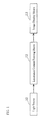
- Fig. 1 shows a block diagram for illustrating a display device constructed according to one embodiment of the present invention, the display device employing a non-emissive type image display means.
- Output light beams emanated from a light source 10 are subject to a luminance gradient forming means 12, which forms a luminance gradient that, for example, substantially monotonously decreases from the center portion of the display screen towards the peripheral portion, and then are supplied to an image display means 13.
- the image display means 13 modulates the supplied images in order to images.
- a gradient such as described above (luminance distribution) is formed in the luminance in the case when a full-white signal is displayed.
- a transmissive liquid crystal panel is used as the image display means.
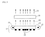
- Fig. 2 shows the construction of a display device according to the present invention, which employs a liquid crystal panel as an image display means.
- the display device include liquid crystal monitors, liquid crystal projectors, and the like.
- the display device basically comprises a light source 15, a backlight 17 also comprising scattering microdots 16, and a transmissive type liquid crystal panel 18 serving as an image display means.
- the light beams from the light source 15 enter from an end face of a transparent light guiding plate 19 and are transmitted between the upper and lower surfaces, repeating the total reflection.
- the back surface of the transparent light guiding plate 19 has a plurality of scattering microdots 16 disposed thereon. All or part of the light incident on the portions where the scattering microdots 16 have been formed changes traveling direction, and the light that is incident on the upper surface of the transparent light guiding plate 19 at an angle smaller than a critical angle (light rays 20 in the figure) exits therefrom and enters the transmissive type liquid crystal panel 18.
- the output light 20 enters the transmissive type liquid crystal panel 205 and is converted into a display image formed of display light 21.
- the scattering microdots 16 may be formed on the back surface of the transparent light guiding plate 19 by screen printing a medium in which microparticles of silicon oxide or titanium oxide are dispersed. Alternatively, they may be realized by forming protrusions on the back surface by injection molding.
- the amount of the light in the periphery is condensed into the center portion of the display image to form a desired luminance gradient.
- Fig. 3 shows a plan view of the scattering microdots 16 formed on a transparent light guiding plate.
- the areas of the scattering microdots 16 are varied so as to form a luminance gradient such that luminance monotonously decreases from the center portion of the display screen towards the peripheral portion.
- a set of scattering microdots 16 having a distribution as shown in Fig. 3 corresponds to the luminance gradient forming means 12 of the present invention.
- Such a distribution of the scattering microdots 16 can be obtained by varying the radii of the scattering microdots 16 in proportion to the values obtained by dividing a desired luminance distribution by a screen luminance distribution that is formed in the case where the radii of scattering microdots 16 are uniform.
- the luminance distribution formed in the case of the radii of the scattering microdots 16 being the same over the entire plane is defined by ⁇ 0(x,y), where the x axis is parallel to the horizontal direction of the screen, the y axis is parallel to the vertical direction of the screen, and the origin is the center of the screen.
- a is a proportionality factor
- luminance gradient function f(x,y) which represents luminance distribution
- a luminance gradient should be formed, when a full-white signal is displayed, so as to substantially monotonously decrease in the horizontal direction and the vertical direction of the displayed image from substantially the center of the displayed image.
- a luminance gradient is formed such that it is substantially symmetrical with respect to the horizontal direction or the vertical direction and substantially monotonously decreases from substantially the center of the display image, the viewer does not easily perceive the luminance distribution.
- a concentric circle-like luminance distribution as shown in Fig. 4 be formed, for example.
- the concentric circle-like luminance gradient can be expressed by setting the luminance distribution profile function r to be (x 2 + y 2 ) (1/2) .
- the term "the concentric circle-like luminance gradient" is intended to indicate that the lines which connect the points having the same luminance form substantially circular shapes.
- the luminance gradient can be expressed by setting the luminance profile function r to be ((x/a) 2 + (y/b) 2 ) (1/2) (where a and b are positive constants).
- the ratio of a and b may be made substantially equal to a common aspect ratio of the screen. For example, it may be made substantially equal to 4:3, 16:9, or 5:4.
- a luminance gradient as shown in Fig. 6 is also preferable.
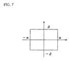
- the luminance gradient can be expressed by making the luminance profile function r to be rect(x/(a ⁇ h), y/(b ⁇ v)), where a and b are positive constants, h is the horizontal length of the screen, v is the vertical length thereof, and rect( ⁇ , ⁇ ) is a special function representing a rectangle as shown in Fig. 7 in which the ratio of the length and the width is ⁇ : ⁇ where ⁇ : ⁇ are defined as 0 ⁇ 1 and 0 ⁇ 1.
- the ratio of a and b may be a common aspect ratio, as in the case of the ellipse.
- the luminance gradient can be made symmetrical with respect to the horizontal axis through the center of the display screen or with respect to the vertical axis through the center of the display screen.
- luminance slope i.e., luminance slope
- luminance gradient be such that f(r) substantially monotonously decreases with respect to r, and, for example, luminance slopes that are represented by the following functions are preferable.
- luminance linearly decreases with respect to r.
- a concentric circle-like luminance distribution profile is employed, and the scattering microdots, serving as the luminance gradient forming means, are formed so that the luminance slope substantially monotonously decreases from substantially the center of the screen according to the Gaussian Function.
- the scattering microdots are adjusted so that the luminance at the boundary of the display screen region having a screen diagonal ratio of 0.9 is 0.55 of that of the center.
- the present inventors have carried out human engineering-based subjective assessment experiment to investigate the proportion of image viewers who perceive luminance variation which continuously changes from the center portion of the display screen towards the peripheral portion.
- the method of the experiment was as follows: subjects were made to observe the images in which the luminance was varied from the center portion of the display screen towards the peripheral portion at various rates and were asked to evaluate unevenness of the luminance according to the double-stimulus impairment scale method, which is a known technique. Degrees of the unevenness were expressed by the ratio of the luminance at the boundary of the display screen region having a screen diagonal ratio of 0.9 and the luminance at the center portion of the screen.
- detection limit luminance 50% of the viewers do not notice a luminance gradient.
- permissible limit luminance 50% of the viewers notice the presence of a little luminance gradient but do not find it distracting.
- tolerable limit luminance 50% of the viewers find it a little distracting but tolerable.
- the detection threshold luminance was determined to be 55% ⁇ 15%, the permissible threshold luminance 30% ⁇ 10%, and the tolerance threshold luminance 15% ⁇ 5%.
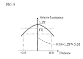
- the arrangement of scattering microdots was designed so that the luminance at the boundary of the display screen region having a screen diagonal ratio of 0.9 was 0.55 with respect to the luminance at the center of the display screen, as shown in Fig. 3.
- the luminance at the center of the display screen is higher by about 27% than a case where the luminance is designed to be uniform over the entire screen, as shown in Fig. 9, because the light that is to go out from the peripheral portion is condensed into the center portion.
- the power consumption is reduced by nearly 30% compared to conventional liquid crystal display devices, while the image observer does not perceive the luminance gradient.
- Fig. 10 shows a block diagram of a display device constructed according to another embodiment of the present invention.
- a feature of the present Embodiment 2 is that input signal is directly controlled to form a luminance gradient. More specifically, while in the foregoing Embodiment 1, the luminance gradient is formed by controlling positions and areas of the scattering microdots formed, in the present Embodiment 2, the luminance gradient is formed by a signal conversion processing of video signals.
- the present Embodiment 2 is applicable to both non-emissive type elements and emissive type elements.
- emissive type elements include CRTs, PDPs (plasma display panel), FEDs (field emission display: displays that utilize electrons discharged due to field effect for electron excitation light emission) ELs (displays which produce light emission using electroluminescence), and LED arrays in which LEDs are arranged two-dimensionally.
- a luminance gradient means for forming a luminance gradient by directly controlling input signals be provided, and it is of course possible to employ non-emissive type image display devices.
- the luminance distribution having the luminance distribution profile and the luminance slope such as described in Embodiment 1 be realized. Specifically, it is preferable that the luminance substantially monotonously decrease from the center portion of the screen towards the peripheral portion, and it is desirable that the slope be substantially approximated by any of the functions described in Embodiment 1.
- the profile of the luminance distribution (the line connecting the points having the same luminance in the screen) is substantially symmetrical with respect to the horizontal and vertical axes, and is substantially the same as any one of concentric circles, ellipses, rectangles, and rhombuses.
- an ordinary video signal passes through a signal processing circuit which comprises a video signal decoding means 30, a signal correcting means 31, and an image device interface means 32, and then enters an image display means 13.
- the video signal decoding means 30 serves the purpose of converting ordinary NTSC signals to each RGB primary color signal and horizontal and vertical synchronizing signals.
- the signal correcting means 31 serves the purpose of correcting each of the RGB signals and inherently corrects gray level characteristics taking into consideration the input-output characteristics of the display device.
- the display device interface means 32 serves the purpose of adjusting the corrected signal such as to match with the signal levels for the image display means 13.
- the signal correcting means 31 of the present invention more specifically, has a gray level characteristic adjusting means 33 for controlling the gray level characteristics for each pixel.
- the gray level characteristic adjusting means 33 has a memory and stores gray scale data for every pixel in the form of a lookup table, so as to modulate video signal in response to synchronizing signals. That is, the signal correcting means 31 and the gray scale adjusting means 33 correspond to the luminance gradient forming means 12.
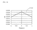
- the gray level characteristic at a point whose luminance is represented by f(x,y) shows the curve as shown in Fig. 12. More specifically, it is only necessary that the gray level characteristics of these points have similarity and that the ratio of approximately f(x,y)/f(0,0).
- a desired luminance gradient can be freely formed in the display screen. Consequently, in the display device constructed according to the present embodiment as well, power consumption can be reduced by forming a luminance gradient which is not perceivable.
- the display element interface means 32 has the functions of the luminance gradient forming means.
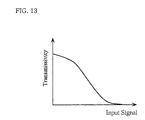
- a case in which a liquid crystal display element is used as the image display means 13 is considered.
- a liquid crystal display element when it is of normally-white mode, has input-output characteristics as shown in Fig. 13. Accordingly, the display element interface means 32 inverses the signals supplied from the signal correcting means 31 so that a desired signal can be obtained.
- the display element interface means 32 varies the gain of a level shifter for each pixel, it is possible to obtain a similar luminance gradient to the case described above, in which gray level characteristics is varied for each pixel.
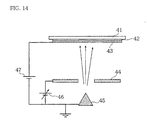
- luminance gradient can be formed by, for example, using an extraction voltage-varying means 40, as shown in Fig. 14.
- the extraction voltage varying means 40 is provided such that it modulates extraction voltage in response to the signal from the display element interface means 32 so that a desired luminance gradient is obtained.
- Shown in Fig. 14 are a substrate 42, phosphors 42, an anode electrode 43, an extraction electrode 44, an electron gun 45, extraction voltage 46, and acceleration voltage 47.
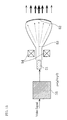
- FIG. 15 A specific configuration in which a CRT is employed for the image display means is shown in Fig. 15. That is, a case where an image display means performs image display by cathode ray scanning which causes the phosphors to emit light.
- the image display means primarily comprises an electron gun 51 and a phosphor screen 52, and electron beams 53 discharged from the electron gun 51 are deflected by a cathode ray deflecting device 54 and the phosphor screen 52 scanned.
- the luminance gradient forming means 55 modulates video signal so as to obtain the luminance distribution profile as described above and realizes a gradual luminance gradient from the center of the display screen towards the peripheral portion.
- the luminance distribution profile and luminance slope as described in Embodiment 1. Specifically, it is preferable to achieve a luminance that substantially monotonously decreases from the center portion of the display screen towards the peripheral portion, and the slopes that are substantially approximated by the functions shown in Embodiment 1. It is also preferable that the profiles of the luminance distribution (lines that connect the points having the same luminance in a display screen) be approximately symmetrical with respect to substantially the horizontal and vertical axes and be substantially equal to concentric circles, ellipses, rectangles, and rhombuses.
- the luminance at the boundary of the display screen region having a screen diagonal ratio of 0.9 is at the detection limit as described in Embodiment 1, it is possible to form a luminance gradient that is even less perceivable.
- the luminance gradients as explained in Embodiment 1 may be formed and the luminance at the boundary of the display screen region having a screen diagonal ratio of 0.9 may be set at threshold luminances, in order to display bright images without making viewers perceive luminance gradient. Further, by reducing the luminance in the peripheral portion, power consumption can be reduced without adversely affecting the viewer impression of brightness.
- Embodiments 1 and 2 have discussed examples in which the luminance slope is such that the luminance at the boundary of the display screen region having a screen diagonal ratio of 0.9 is approximately the detection limit luminance (about 55% luminance of the luminance of the center portion). This is a level at which the results of the subjective assessment show that 50% or more observers do not notice the unevenness in the brightness. Nevertheless, when further reduction in power consumption is desired, it is of course possible that, in the display devices described in Embodiments 1 to 3, the luminance slope is formed such that the luminance at the boundary of the display screen region having a screen diagonal ratio of 0.9 is reduced to the permissible limit luminance or the tolerable limit luminance (limit for practical use). In this case, the luminance slope is of course likely to be detected. For this reason, the present embodiment describes in detail an embodiment of a display device in which such a luminance slope is made even less detectable.
- Luminance referred to in the present embodiment is a physical quantity which is directly measurable with the use of instruments and is an index showing brightness. However, it does not necessarily match the psychological impression of brightness held by the image viewers. In other words, even when luminances are the same, the psychological impression perceived by viewers varies depending on contrast and gray level characteristics.
- L is a luminance when displaying a full white signal.
- CR photopic contrast, which means a contrast in which ambient light is taken into consideration.
- Cr scotopic contrast, which means a contrast measured in a surrounding environment where no ambient light exists (that is, in a condition where illuminance is 0).
- OFF luminance when displaying a full-black signal and there is no effect due to ambient light.
- BG denotes luminance increase caused by ambient light.
- a, b, c, and d are coefficients and in the following ranges.
- the coefficients a, b, d, and g may be arbitrary values within the range from the lowest permissible values to the highest permissible values.
- si is the input signal level for displaying the i-th gray level.
- the maximum value of the input signal level is standardized at 255.
- Table 1 is provided to show the relationship between the characteristic values of the ordinary gray level characteristics, represented using exponential functions, and the gray level characteristics defined according to the present invention. ⁇ 1.6 1.8 2 2.2 2.4 2.6 2.8 3 ⁇ M 0.001824 0.002277 0.0027 0.003105 0.003496 0.003877 0.004251 0.00462
- Coefficient ⁇ M is employed as a coefficient relating to gray level characteristics because, even in cases where devices have input-output characteristics such that the ⁇ value is not constant (for example, liquid crystal display elements generally show S-like shaped display characteristic curves), the ⁇ values can be represented by one standardized ⁇ value.
- the brightness index which is approximately proportional to psychological impression of brightness, decreases according to Eq. 3.
- the decrease is not easily perceived as being a luminance slope. This is due to the fact that when a human observes a display screen, he or she does not observe the entire region thereof at once but rather observes a local region thereof, which causes a kind of optical illusion.
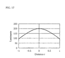
- the luminance gradient as shown in Fig. 17 is provided.
- the horizontal axis denotes distance expressed by screen diagonal
- the vertical axis denotes relative luminance when the luminance of the center is the reference point.
- the luminance is about 55% (detection limit luminance).
- the brightness index decreases towards the periphery, as shown in Fig. 18.
- the luminance gradient gradually becomes more perceivable.
- luminance variation is made less perceivable by varying gray level characteristics in the display screen in the manner such as described above.
- the display device comprises a brightness index improving means.
- the brightness index improving means comprises, like the luminance gradient forming means described in Embodiment 2, a gray level characteristic adjusting means, and has a function for predetermining gray level characteristics according to the positions in the display screen so that the gray level characteristics are as shown in Fig. 19.
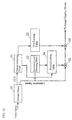
- Fig. 21 is a block diagram showing a specific configuration of a signal processing unit of a display device according to Embodiment 3.
- Reference numeral 50 denotes a decoder means, and the decoder means 50 separates a composite video signal into a luminance signal and a horizontal and a vertical synchronizing signal.
- Reference numeral 51 denotes a position detecting means in which two-dimensional positional coordinates of pixels (or dots) are detected, which is realized by, for example, a counter or the like.
- Reference numeral 52 denotes a luminance level detecting means for detecting a signal voltage level of video signal for each pixel.
- Reference numeral 53 denotes a first lookup table. As shown in Fig.
- the first lookup table 53 stores second multiplication gains which correspond to two-dimensional coordinate data, and upon receiving two-dimensional coordinate data from the position detecting means, it outputs first multiplication gains corresponding to the input.
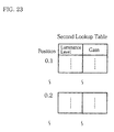
- Reference numeral 54 denotes a second lookup table. As shown in Fig. 23, in order to vary the ⁇ M value for the peripheral portion of the display screen, the second lookup table 54 stores second multiplication gains corresponding to two-dimensional coordinates and luminance levels, and upon receiving two-dimensional coordinate data from the position detecting means and luminance level data from the luminance level detecting means, outputs second multiplication gains corresponding to the input.
- Reference numeral 55 denotes a first multiplying means and 56 a second multiplying means.
- the multiplication gains are determined by two parameters, positions of pixels and signal levels.
- ⁇ curves shown in Fig. 24(c) may be employed in place of the ⁇ curves shown in Fig. 24(b). Advantages and effects of employing the ⁇ curves shown in Fig. 24(c) will be discussed later.
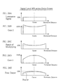
- Figs. 25 to 27 show examples of signal conversion concerning a scanning line through substantially the center of the display screen, Fig. 25 showing a case when all the signal levels for the scanning line are 100% luminance, Fig. 26 a case when all the signal levels are 50% luminance, and Fig. 27 a case when the first half of the signal levels for the scanning line is 50% while the second half is 100% luminance.
- Figs. 25(a) to (e) in the case of the signal levels shown in Fig. 25(a), the second multiplication gains read out from the second lookup table 54 are as shown in Fig. 25(b).
- output from the first multiplying means 55 is as shown in Fig. 25(c).
- the first lookup table 53 outputs first multiplication gains such that brightness index BI is substantially monotonously decreased from substantially the center portion of the display screen towards the peripheral portion, and as a result, the scanning line as a whole shows a gain characteristic as shown in Fig. 25(d).
- the second multiplying means 56 multiplies the luminance levels as shown in Fig. 25(c) with the luminance levels shown in as Fig. 25(d), whereby luminance levels as shown in Fig. 25(e) result.
- the luminance signal as shown in Fig. 25(a) is signal converted into the luminance signal as shown in Fig. 25(e).
- the luminance signal is signal converted into a luminance signal as shown in Fig. 26(e).
- luminance levels are increased by varying the gray level characteristics of halftone levels.
- the luminance signal is signal converted into a luminance signal as shown in Fig. 27(e).
- luminance levels are increased by varying gray level characteristics.
- brightness index BI is improved so that brightness index substantially monotonously decreases from substantially the center portion of the display screen towards the peripheral portion and luminance level increases in the peripheral portion, and thereby, compared to cases where luminance is made uniform over the entire screen, reduction in power consumption is achieved without reducing the viewer impression of brightness.
- multiplication gains are determined based on only one parameter, positions of pixels, and the obtained multiplication gains are multiplied with the signal levels of the video signal, so that the center of the display screen is made bright and the periphery dark.
- gains are the same for every gray level, that is, every gray level has the same decrease rate, and the luminance gradient is easily perceived.
- the gains vary for each gray level, and as a consequence, by reducing the gains for lower gray levels, luminance gradient is made less noticeable.
- the second multiplication gains are determined based on the ⁇ curves shown in Fig. 24(b)
- the ⁇ curves shown in Fig. 24(c) may be used in place of the ⁇ curves shown in Fig. 24(b).
- luminance is previously decreased in the peripheral portion by using the first multiplication gains, and the gray level characteristics are compensated in all the regions from white level to halftone regions.
- luminance is made uniform over the entire display screen (or very slightly decreased in the peripheral portion), and the gray level characteristics are not compensated at the white level but they are compensated only in halftone regions to perform display.
- a first lookup table 53 is used such that the first multiplication gains of approximately "1" result for any positions, and the second lookup table stores gains such that the ⁇ curves shown in Fig. 24(c) are obtained.
- the second lookup table stores gains such that the ⁇ curves shown in Fig. 24(c) are obtained.
- the first lookup table 53 may be omitted.
- Fig. 28 shows a block diagram illustrating the configuration of the signal processing unit in a display device according to Embodiment 4.
- Embodiment 4 is analogous to the foregoing Embodiment 3, and like parts are indicated by like reference numerals.
- a characteristic feature of Embodiment 4 is that fluctuation of photopic contrast CR caused by ambient light is compensated and thereby the viewer's perception of brightness is maintained without being affected by ambient light. Referring to Fig. 28, the specific configuration is described below.
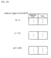
- an ambient light detecting means 57 for detecting ambient light levels is additionally provided, and in place of the second lookup table 54, a third lookup table 58 is provided.
- the third lookup table 58 stores, as shown in Fig.
- the first lookup table is not necessarily an essential component.
- Fig. 30 shows a block diagram illustrating the configuration of a signal processing unit in a display device according to Embodiment 5.
- Embodiment 5 is similar to Embodiment 4, and like parts are referred to by like reference numerals.
- Embodiment 5 is characterized in that fluctuation of peak luminance induced by operating time of a display device is compensated and thereby viewer's perception of brightness is maintained without being affected by the operating time.
- an operating time detecting means 59 for detecting the operating time of the display device is provided in place of the ambient light detecting means 57 described in the foregoing Embodiment 4, and a fourth lookup table 60 is provided in place of the third lookup table 58.
- the fourth lookup table 60 stores fourth multiplication gains in order to compensate the peak luminance caused to fluctuate by the operating time.
- the operating time detecting means 59 is realized by, for example, a timer or the like.
- the operation in this configuration is basically the same as that illustrated in Figs. 25-27. According to the operation illustrated in Figs. 25-27, the brightness index caused to fluctuate by operating time is improved, and this makes it possible to maintain viewer's perception of brightness without being affected by operating time.
- the first lookup table is not necessarily an essential component.
- Fig. 31 shows a block diagram illustrating the configuration of a signal processing unit in a display device according to Embodiment 6.
- Embodiment 6 is similar to Embodiment 5 described above, and like parts are referred to by like reference numerals.
- time variation detecting means 61 for detecting variation over time is provided in place of the operating time detecting means 59 provided in Embodiment 5, and in place of the fourth lookup table 60, a fifth lookup table 62 is provided that stores fifth multiplication gains for compensating the peak luminance that is caused to fluctuate due to variation over time.
- the time variation detecting means 61 is realized, for example, by a light sensor that detects an actual luminance at the display screen.
- the peak luminance that decreases over a certain time is determined by prescribed data, but the time variation detecting means 61 differs therefrom in that it detects an actual decrease of the peak luminance.
- the brightness index that has been caused to fluctuate because of variation over time is improved, and this makes it possible to maintain perceived brightness without being affected by variation over time.
- the first lookup table is not necessarily an essential component.
Landscapes
- Physics & Mathematics (AREA)
- Engineering & Computer Science (AREA)
- General Physics & Mathematics (AREA)
- Optics & Photonics (AREA)
- Computer Hardware Design (AREA)
- Theoretical Computer Science (AREA)
- Multimedia (AREA)
- Signal Processing (AREA)
- Control Of Indicators Other Than Cathode Ray Tubes (AREA)
- Controls And Circuits For Display Device (AREA)
Applications Claiming Priority (5)
| Application Number | Priority Date | Filing Date | Title |
|---|---|---|---|
| JP26296899 | 1999-09-17 | ||
| JP26296899 | 1999-09-17 | ||
| JP2000157757 | 2000-05-29 | ||
| JP2000157757 | 2000-05-29 | ||
| PCT/JP2000/006341 WO2001022391A1 (fr) | 1999-09-17 | 2000-09-18 | Dispositif afficheur d'images |
Publications (1)
| Publication Number | Publication Date |
|---|---|
| EP1237138A1 true EP1237138A1 (fr) | 2002-09-04 |
Family
ID=26545793
Family Applications (1)
| Application Number | Title | Priority Date | Filing Date |
|---|---|---|---|
| EP00961044A Withdrawn EP1237138A1 (fr) | 1999-09-17 | 2000-09-18 | Dispositif afficheur d'images |
Country Status (5)
| Country | Link |
|---|---|
| US (1) | US6791566B1 (fr) |
| EP (1) | EP1237138A1 (fr) |
| KR (1) | KR20020019517A (fr) |
| TW (1) | TW501079B (fr) |
| WO (1) | WO2001022391A1 (fr) |
Cited By (13)
| Publication number | Priority date | Publication date | Assignee | Title |
|---|---|---|---|---|
| GB2414130A (en) * | 2004-05-11 | 2005-11-16 | Hitachi Ltd | Reducing brightness in the peripheral part of a display panel |
| EP1564479A4 (fr) * | 2002-09-30 | 2008-01-23 | Sharp Kk | Unite de retroeclairage et afficheur a cristaux liquides l'utilisant |
| WO2008099319A1 (fr) * | 2007-02-16 | 2008-08-21 | Koninklijke Philips Electronics N.V. | Gradation en 2d d'un élément d'illumination pour un dispositif d'affichage |
| EP1414012A4 (fr) * | 2001-07-27 | 2008-10-29 | Sony Corp | Appareil de traitement non lineaire, appareil d'affichage d'images |
| EP1564478A4 (fr) * | 2002-10-22 | 2008-12-10 | Sharp Kk | Unite de retroeclairage et unite d'affichage a cristaux liquides utilisant une unite de retroeclairage |
| EP1881476A3 (fr) * | 2006-07-20 | 2009-07-01 | LG Electronics Inc. | Dispositif de commande d'un panneau d'affichage plasma et procédé de commande associé |
| EP1809032A4 (fr) * | 2004-11-05 | 2010-01-27 | Panasonic Corp | Dispositif de transformation de signal vidéo et dispositif d affichage vidéo |
| CN101923827A (zh) * | 2009-06-16 | 2010-12-22 | 索尼公司 | 自发光显示设备,功耗降低方法和程序 |
| WO2010145968A1 (fr) * | 2009-06-18 | 2010-12-23 | Thomson Licensing | Procédé de traitement d'images |
| EP2296137A1 (fr) * | 2009-09-07 | 2011-03-16 | Nxp B.V. | Dispositif d'affichage d'images et son procédé de fonctionnement |
| FR2950182A1 (fr) * | 2009-09-16 | 2011-03-18 | Thomson Licensing | Procede de traitement d'image |
| EP1870878A3 (fr) * | 2006-06-19 | 2012-03-21 | Samsung Electronics Co., Ltd. | Appareil de traitement d'images et procédé de réduction de la consommation d'énergie d'un affichage autolumineux |
| US9070316B2 (en) | 2004-10-25 | 2015-06-30 | Barco Nv | Optical correction for high uniformity panel lights |
Families Citing this family (53)
| Publication number | Priority date | Publication date | Assignee | Title |
|---|---|---|---|---|
| US7046255B2 (en) * | 2001-06-28 | 2006-05-16 | Hewlett-Packard Development Company, L.P. | Hardware-based accelerated color correction filtering system |
| US7036025B2 (en) * | 2002-02-07 | 2006-04-25 | Intel Corporation | Method and apparatus to reduce power consumption of a computer system display screen |
| JP4317354B2 (ja) * | 2002-10-25 | 2009-08-19 | シャープ株式会社 | 光源装置及びそれを備えた表示装置 |
| US20040100426A1 (en) * | 2002-11-21 | 2004-05-27 | Madhukar Gaganam | Field emission display brightness uniformity compensation system and method |
| JP2005004118A (ja) * | 2003-06-16 | 2005-01-06 | Hitachi Ltd | 表示装置 |
| JP2005004117A (ja) * | 2003-06-16 | 2005-01-06 | Hitachi Ltd | 表示装置 |
| US7714831B2 (en) | 2003-07-16 | 2010-05-11 | Honeywood Technologies, Llc | Background plateau manipulation for display device power conservation |
| US7583260B2 (en) * | 2003-07-16 | 2009-09-01 | Honeywood Technologies, Llc | Color preservation for spatially varying power conservation |
| US7602388B2 (en) * | 2003-07-16 | 2009-10-13 | Honeywood Technologies, Llc | Edge preservation for spatially varying power conservation |
| US20060020906A1 (en) * | 2003-07-16 | 2006-01-26 | Plut William J | Graphics preservation for spatially varying display device power conversation |
| US7580033B2 (en) * | 2003-07-16 | 2009-08-25 | Honeywood Technologies, Llc | Spatial-based power savings |
| US7786988B2 (en) | 2003-07-16 | 2010-08-31 | Honeywood Technologies, Llc | Window information preservation for spatially varying power conservation |
| US7663597B2 (en) * | 2003-07-16 | 2010-02-16 | Honeywood Technologies, Llc | LCD plateau power conservation |
| JP4114655B2 (ja) * | 2003-11-12 | 2008-07-09 | セイコーエプソン株式会社 | 輝度ムラの補正方法、輝度ムラの補正回路、電気光学装置および電子機器 |
| KR100547979B1 (ko) * | 2003-12-01 | 2006-02-02 | 엘지전자 주식회사 | 플라즈마 디스플레이 패널의 구동 장치 및 방법 |
| US7929796B2 (en) * | 2004-09-07 | 2011-04-19 | Nec Corporation | Image processing system and method, and terminal and server used for the same |
| JP2006128093A (ja) | 2004-09-28 | 2006-05-18 | Mitsubishi Rayon Co Ltd | 面光源装置用導光体および面光源装置 |
| US20060161543A1 (en) * | 2005-01-19 | 2006-07-20 | Tiny Engine, Inc. | Systems and methods for providing search results based on linguistic analysis |
| US20060161553A1 (en) * | 2005-01-19 | 2006-07-20 | Tiny Engine, Inc. | Systems and methods for providing user interaction based profiles |
| US20060161587A1 (en) * | 2005-01-19 | 2006-07-20 | Tiny Engine, Inc. | Psycho-analytical system and method for audio and visual indexing, searching and retrieval |
| US7169920B2 (en) * | 2005-04-22 | 2007-01-30 | Xerox Corporation | Photoreceptors |
| KR100707639B1 (ko) * | 2005-04-28 | 2007-04-13 | 삼성에스디아이 주식회사 | 발광 표시장치 및 그의 구동 방법 |
| US7602408B2 (en) | 2005-05-04 | 2009-10-13 | Honeywood Technologies, Llc | Luminance suppression power conservation |
| US7760210B2 (en) * | 2005-05-04 | 2010-07-20 | Honeywood Technologies, Llc | White-based power savings |
| JP5013581B2 (ja) * | 2005-05-26 | 2012-08-29 | ルネサスエレクトロニクス株式会社 | 表示装置、コントローラドライバ、及び表示パネルの駆動方法 |
| TWI335570B (en) * | 2006-04-17 | 2011-01-01 | Au Optronics Corp | Active matrix organic light emitting diode display capable of driving pixels according to display resolution and related driving method |
| KR100827619B1 (ko) * | 2006-10-11 | 2008-05-07 | 삼성전기주식회사 | 영상 왜곡 보정 방법 및 그 장치 |
| JP5111872B2 (ja) * | 2007-01-23 | 2013-01-09 | パナソニック株式会社 | 映像信号処理装置、映像信号処理方法、映像信号処理プログラムおよび映像信号表示装置 |
| JP5425382B2 (ja) * | 2007-08-27 | 2014-02-26 | エルジー ディスプレイ カンパニー リミテッド | デジタル表示装置の駆動装置 |
| WO2009141980A1 (fr) * | 2008-05-21 | 2009-11-26 | パナソニック株式会社 | Dispositif d'affichage de signal vidéo, procédé d'affichage de signal vidéo, programme et circuit intégré |
| JP2010127994A (ja) * | 2008-11-25 | 2010-06-10 | Sony Corp | 補正値算出方法、表示装置 |
| JP5341103B2 (ja) * | 2008-11-26 | 2013-11-13 | シャープ株式会社 | 液晶表示装置、液晶表示装置の駆動方法、テレビジョン受像機 |
| US8743047B2 (en) * | 2008-11-26 | 2014-06-03 | Sharp Kabushiki Kaisha | Liquid crystal display device, method for driving liquid crystal display device, and television receiver |
| CN102265327B (zh) * | 2008-12-25 | 2014-10-01 | 夏普株式会社 | 显示装置和显示装置的驱动方法 |
| JP2010160272A (ja) * | 2009-01-07 | 2010-07-22 | Canon Inc | 表示制御装置およびその制御方法 |
| JP4982510B2 (ja) * | 2009-01-23 | 2012-07-25 | 株式会社日立製作所 | 映像表示装置 |
| US20110234625A1 (en) * | 2009-01-30 | 2011-09-29 | Sharp Kabushiki Kaisha | Display device and method for driving same |
| JP5152084B2 (ja) * | 2009-04-15 | 2013-02-27 | ソニー株式会社 | 画像表示装置 |
| JP5650422B2 (ja) * | 2010-03-24 | 2015-01-07 | ソニー株式会社 | 液晶表示装置 |
| JP5560076B2 (ja) | 2010-03-25 | 2014-07-23 | パナソニック株式会社 | 有機el表示装置及びその製造方法 |
| JP5560077B2 (ja) | 2010-03-25 | 2014-07-23 | パナソニック株式会社 | 有機el表示装置及びその製造方法 |
| US9324300B2 (en) | 2012-02-15 | 2016-04-26 | Mario Diez | Extending battery life by automatic control of display illumination |
| JP6697849B2 (ja) * | 2015-01-21 | 2020-05-27 | ソニー株式会社 | ウェアラブルディスプレイ装置および画像表示方法 |
| US10019952B2 (en) | 2016-07-15 | 2018-07-10 | Himax Display, Inc. | Liquid crystal on silicon display with brightness adjustment |
| TWI646524B (zh) * | 2016-07-28 | 2019-01-01 | 立景光電股份有限公司 | 液晶覆矽顯示器與其亮度調整方法 |
| KR102423637B1 (ko) | 2017-10-27 | 2022-07-22 | 삼성디스플레이 주식회사 | 표시장치 및 이의 구동방법 |
| WO2019244260A1 (fr) | 2018-06-19 | 2019-12-26 | 株式会社ソシオネクスト | Procédé de détermination de luminance, dispositif de détermination de luminance et dispositif d'affichage d'image |
| DE102021200857A1 (de) * | 2020-05-15 | 2021-11-18 | Continental Automotive Gmbh | Anzeigeelement mit im Randbereich reduzierter Hintergrundbeleuchtung |
| KR102870350B1 (ko) * | 2021-04-14 | 2025-10-13 | 삼성전자 주식회사 | 무선 통신 시스템에서 시간 정렬 오차(timing alignment error, TAE)에 기반하여 통신을 수행하기 위한 장치 및 방법 |
| US11490151B1 (en) * | 2021-07-22 | 2022-11-01 | Roku, Inc. | Ambient light sensor based picture enhancement |
| CN119998862A (zh) * | 2022-12-22 | 2025-05-13 | 谷歌有限责任公司 | 显示器外围的可变亮度调光 |
| CN116647726A (zh) * | 2023-04-28 | 2023-08-25 | 海信视像科技股份有限公司 | 一种显示设备的画面画质调节方法及显示设备 |
| CN117475892A (zh) * | 2023-05-15 | 2024-01-30 | 深圳市华星光电半导体显示技术有限公司 | 亮度补偿方法以及亮度补偿装置 |
Family Cites Families (24)
| Publication number | Priority date | Publication date | Assignee | Title |
|---|---|---|---|---|
| JPS50157013A (fr) * | 1974-06-07 | 1975-12-18 | ||
| US4487481A (en) | 1980-03-24 | 1984-12-11 | Epson Corporation | Backlighted liquid crystal display |
| JPS5713478A (en) | 1980-06-26 | 1982-01-23 | Epson Corp | Back light structure for display unit |
| JPH0824340B2 (ja) * | 1984-11-15 | 1996-03-06 | キヤノン株式会社 | 画像信号処理装置 |
| JPS6320680A (ja) | 1986-07-15 | 1988-01-28 | Omron Tateisi Electronics Co | 記憶媒体装置 |
| JPS6320680U (fr) * | 1986-07-25 | 1988-02-10 | ||
| JPH0638083B2 (ja) * | 1988-06-20 | 1994-05-18 | 横河電機株式会社 | 波形表示装置 |
| JPH035725A (ja) * | 1989-06-02 | 1991-01-11 | Mitsubishi Petrochem Co Ltd | バックライト装置 |
| JPH0351889A (ja) * | 1989-07-20 | 1991-03-06 | Fujitsu General Ltd | 投写型ディスプレイ |
| JPH0362796A (ja) * | 1989-07-31 | 1991-03-18 | Toppan Printing Co Ltd | カラーモニタの色バランス調整装置 |
| JPH06161371A (ja) | 1992-11-18 | 1994-06-07 | Sanyo Electric Co Ltd | 階調補正装置 |
| DE69414153T2 (de) * | 1993-02-24 | 1999-06-10 | Matsushita Electric Industrial Co., Ltd., Kadoma, Osaka | Vorrichtung zur Gradationskorrektur und Bildaufnahmegerät mit einer solchen Vorrichtung |
| JP3115727B2 (ja) | 1993-03-25 | 2000-12-11 | パイオニア株式会社 | プラズマディスプレイパネルの駆動装置 |
| JPH0777665A (ja) * | 1993-03-29 | 1995-03-20 | Canon Inc | 画像表示装置及びその為の画像撮影装置 |
| JPH0815701A (ja) * | 1994-06-29 | 1996-01-19 | Hitachi Ltd | 投射型液晶表示装置用照明装置、及びこれを用いた液晶表示装置 |
| JPH08101660A (ja) | 1994-09-30 | 1996-04-16 | Matsushita Electric Works Ltd | 表示装置 |
| JP3891499B2 (ja) * | 1995-04-14 | 2007-03-14 | パイオニア株式会社 | プラズマディスプレイパネルにおける輝度調整装置 |
| JP3242304B2 (ja) * | 1995-10-03 | 2001-12-25 | シャープ株式会社 | マトリクス型表示装置 |
| JPH09101761A (ja) | 1995-10-03 | 1997-04-15 | Casio Comput Co Ltd | El表示装置 |
| US6271825B1 (en) * | 1996-04-23 | 2001-08-07 | Rainbow Displays, Inc. | Correction methods for brightness in electronic display |
| JP2950274B2 (ja) * | 1997-01-28 | 1999-09-20 | 日本電気株式会社 | 電界放出型冷陰極素子の駆動方法及び電界放出型冷陰極電子銃 |
| JPH1195735A (ja) * | 1997-09-18 | 1999-04-09 | Fuji Photo Film Co Ltd | 画像表示装置 |
| JP4230549B2 (ja) | 1997-10-03 | 2009-02-25 | ソニー株式会社 | 非線形補正回路及びそれを用いた画像表示装置 |
| US6208327B1 (en) * | 1998-07-31 | 2001-03-27 | International Business Machines Corporation | Camouflage of imaged post spacers and compensation of pixels that depart from nominal operating conditions by luminance diffusion |
-
2000
- 2000-09-18 EP EP00961044A patent/EP1237138A1/fr not_active Withdrawn
- 2000-09-18 WO PCT/JP2000/006341 patent/WO2001022391A1/fr not_active Ceased
- 2000-09-18 US US10/088,418 patent/US6791566B1/en not_active Expired - Fee Related
- 2000-09-18 TW TW089119129A patent/TW501079B/zh active
- 2000-09-18 KR KR1020027000502A patent/KR20020019517A/ko not_active Ceased
Non-Patent Citations (1)
| Title |
|---|
| See references of WO0122391A1 * |
Cited By (22)
| Publication number | Priority date | Publication date | Assignee | Title |
|---|---|---|---|---|
| US8098335B2 (en) | 2001-07-27 | 2012-01-17 | Sony Corporation | Nonlinear processing device and image display apparatus |
| EP1414012A4 (fr) * | 2001-07-27 | 2008-10-29 | Sony Corp | Appareil de traitement non lineaire, appareil d'affichage d'images |
| EP1564479A4 (fr) * | 2002-09-30 | 2008-01-23 | Sharp Kk | Unite de retroeclairage et afficheur a cristaux liquides l'utilisant |
| US7901103B2 (en) | 2002-10-22 | 2011-03-08 | Sharp Kabushiki Kaisha | Backlight unit and liquid crystal display device using the backlight unit |
| EP1564478A4 (fr) * | 2002-10-22 | 2008-12-10 | Sharp Kk | Unite de retroeclairage et unite d'affichage a cristaux liquides utilisant une unite de retroeclairage |
| EP2071552A3 (fr) * | 2002-10-22 | 2009-10-21 | Sharp Kabushiki Kaisha | Uunité de retroeclairage et unité d'affichage à cristaux liquides utilisant une unité de retroéclairage |
| GB2414130B (en) * | 2004-05-11 | 2006-07-19 | Hitachi Ltd | Video display apparatus |
| GB2414130A (en) * | 2004-05-11 | 2005-11-16 | Hitachi Ltd | Reducing brightness in the peripheral part of a display panel |
| US9070316B2 (en) | 2004-10-25 | 2015-06-30 | Barco Nv | Optical correction for high uniformity panel lights |
| US7956927B2 (en) | 2004-11-05 | 2011-06-07 | Panasonic Corporation | Video signal converter and video display device |
| EP1809032A4 (fr) * | 2004-11-05 | 2010-01-27 | Panasonic Corp | Dispositif de transformation de signal vidéo et dispositif d affichage vidéo |
| EP1870878A3 (fr) * | 2006-06-19 | 2012-03-21 | Samsung Electronics Co., Ltd. | Appareil de traitement d'images et procédé de réduction de la consommation d'énergie d'un affichage autolumineux |
| EP1881476A3 (fr) * | 2006-07-20 | 2009-07-01 | LG Electronics Inc. | Dispositif de commande d'un panneau d'affichage plasma et procédé de commande associé |
| WO2008099319A1 (fr) * | 2007-02-16 | 2008-08-21 | Koninklijke Philips Electronics N.V. | Gradation en 2d d'un élément d'illumination pour un dispositif d'affichage |
| CN101923827A (zh) * | 2009-06-16 | 2010-12-22 | 索尼公司 | 自发光显示设备,功耗降低方法和程序 |
| WO2010145968A1 (fr) * | 2009-06-18 | 2010-12-23 | Thomson Licensing | Procédé de traitement d'images |
| FR2947081A1 (fr) * | 2009-06-18 | 2010-12-24 | Thomson Licensing | Procede de traitement d'image. |
| US20110063338A1 (en) * | 2009-09-07 | 2011-03-17 | Nxp B.V. | Image display device and method of its operation |
| EP2296137A1 (fr) * | 2009-09-07 | 2011-03-16 | Nxp B.V. | Dispositif d'affichage d'images et son procédé de fonctionnement |
| WO2011032913A1 (fr) * | 2009-09-16 | 2011-03-24 | Thomson Licensing | Procédé de traitement d'image |
| FR2950182A1 (fr) * | 2009-09-16 | 2011-03-18 | Thomson Licensing | Procede de traitement d'image |
| US8803904B2 (en) | 2009-09-16 | 2014-08-12 | Thomson Licensing | Image processing method |
Also Published As
| Publication number | Publication date |
|---|---|
| TW501079B (en) | 2002-09-01 |
| WO2001022391A1 (fr) | 2001-03-29 |
| US6791566B1 (en) | 2004-09-14 |
| KR20020019517A (ko) | 2002-03-12 |
Similar Documents
| Publication | Publication Date | Title |
|---|---|---|
| US6791566B1 (en) | Image display device | |
| EP1705636B1 (fr) | Appareil et procédé d'affichage | |
| US8144173B2 (en) | Image processing apparatus and image display apparatus | |
| CN101354504B (zh) | 堆叠式lcd单元 | |
| JP2002055675A (ja) | 画像表示装置 | |
| JP5460435B2 (ja) | 画像表示装置および画像表示装置の制御方法 | |
| US8089449B2 (en) | Liquid crystal display apparatus | |
| US9214112B2 (en) | Display device and display method | |
| CN112419990A (zh) | 显示设备及其控制方法和存储介质 | |
| US20060221046A1 (en) | Display device and method of driving display device | |
| US20120162532A1 (en) | Liquid crystal display apparatus and television receiver | |
| KR100959594B1 (ko) | 액정 표시 장치 및 이에 이용되는 영상 표시 방법 | |
| EP2166531A2 (fr) | Appareil de contrôle d'éclairage de la lumière de rétroéclairage et appareil d'affichage vidéo | |
| US8155435B2 (en) | Display apparatus and its control method | |
| US20110057967A1 (en) | Image display device | |
| US20160033795A1 (en) | Testing device, method thereof, display device and display method thereof | |
| US8289272B2 (en) | Control of a display | |
| US10573249B2 (en) | Display control | |
| JP2010175913A (ja) | 画像表示装置 | |
| US20110115829A1 (en) | Image display apparatus and control apparatus thereof | |
| US20210012727A1 (en) | Method for controlling light source of display device and lcd device | |
| US20100060672A1 (en) | Liquid crystal display system and method | |
| US20090021458A1 (en) | High contrast liquid crystal display | |
| KR101596463B1 (ko) | 이미지의 특성에 따른 백라이트 디밍 방법과 그 방법을 위한 장치 | |
| US8537148B2 (en) | Image display apparatus and image display method |
Legal Events
| Date | Code | Title | Description |
|---|---|---|---|
| PUAI | Public reference made under article 153(3) epc to a published international application that has entered the european phase |
Free format text: ORIGINAL CODE: 0009012 |
|
| 17P | Request for examination filed |
Effective date: 20020503 |
|
| AK | Designated contracting states |
Kind code of ref document: A1 Designated state(s): AT BE CH CY DE DK ES FI FR GB GR IE IT LI LU MC NL PT SE |
|
| RIN1 | Information on inventor provided before grant (corrected) |
Inventor name: KOMORI, KAZUNORI Inventor name: UEMURA, TSUYOSHI Inventor name: ASAYAMA, JUNKO Inventor name: KURATOMI, YASUNORI BYUKSAN APT Inventor name: OGIWARA, AKIFUMI |
|
| STAA | Information on the status of an ep patent application or granted ep patent |
Free format text: STATUS: THE APPLICATION HAS BEEN WITHDRAWN |
|
| 18W | Application withdrawn |
Effective date: 20050608 |