EP1237018A2 - Dispositif à fibre optique et son procédé de fabrication - Google Patents
Dispositif à fibre optique et son procédé de fabrication Download PDFInfo
- Publication number
- EP1237018A2 EP1237018A2 EP01124296A EP01124296A EP1237018A2 EP 1237018 A2 EP1237018 A2 EP 1237018A2 EP 01124296 A EP01124296 A EP 01124296A EP 01124296 A EP01124296 A EP 01124296A EP 1237018 A2 EP1237018 A2 EP 1237018A2
- Authority
- EP
- European Patent Office
- Prior art keywords
- optical fiber
- optical fibers
- mode field
- fused point
- fiber device
- Prior art date
- Legal status (The legal status is an assumption and is not a legal conclusion. Google has not performed a legal analysis and makes no representation as to the accuracy of the status listed.)
- Withdrawn
Links
- 239000013307 optical fiber Substances 0.000 title claims abstract description 346
- 238000004519 manufacturing process Methods 0.000 title claims description 14
- 238000007526 fusion splicing Methods 0.000 claims abstract description 54
- 238000010438 heat treatment Methods 0.000 claims description 98
- 238000000034 method Methods 0.000 claims description 14
- 239000007789 gas Substances 0.000 claims description 10
- MYMOFIZGZYHOMD-UHFFFAOYSA-N Dioxygen Chemical compound O=O MYMOFIZGZYHOMD-UHFFFAOYSA-N 0.000 claims description 8
- 229910001882 dioxygen Inorganic materials 0.000 claims description 8
- 230000000452 restraining effect Effects 0.000 abstract 1
- 238000009826 distribution Methods 0.000 description 25
- 230000014509 gene expression Effects 0.000 description 18
- 230000005855 radiation Effects 0.000 description 14
- ATUOYWHBWRKTHZ-UHFFFAOYSA-N Propane Chemical compound CCC ATUOYWHBWRKTHZ-UHFFFAOYSA-N 0.000 description 10
- 230000003287 optical effect Effects 0.000 description 7
- 239000002019 doping agent Substances 0.000 description 6
- 239000001294 propane Substances 0.000 description 5
- VYPSYNLAJGMNEJ-UHFFFAOYSA-N Silicium dioxide Chemical compound O=[Si]=O VYPSYNLAJGMNEJ-UHFFFAOYSA-N 0.000 description 4
- 230000007423 decrease Effects 0.000 description 4
- 239000012535 impurity Substances 0.000 description 4
- 239000006185 dispersion Substances 0.000 description 3
- 230000005540 biological transmission Effects 0.000 description 2
- 238000005259 measurement Methods 0.000 description 2
- 238000012986 modification Methods 0.000 description 2
- 230000004048 modification Effects 0.000 description 2
- 238000004458 analytical method Methods 0.000 description 1
- 239000003795 chemical substances by application Substances 0.000 description 1
- 238000005253 cladding Methods 0.000 description 1
- 238000000576 coating method Methods 0.000 description 1
- 239000000470 constituent Substances 0.000 description 1
- 238000007796 conventional method Methods 0.000 description 1
- 238000005520 cutting process Methods 0.000 description 1
- 238000007599 discharging Methods 0.000 description 1
- 238000004453 electron probe microanalysis Methods 0.000 description 1
- 238000005516 engineering process Methods 0.000 description 1
- 239000002075 main ingredient Substances 0.000 description 1
- 239000002184 metal Substances 0.000 description 1
- 230000001902 propagating effect Effects 0.000 description 1
- 230000001105 regulatory effect Effects 0.000 description 1
- 235000012239 silicon dioxide Nutrition 0.000 description 1
Images


Classifications
-
- G—PHYSICS
- G02—OPTICS
- G02B—OPTICAL ELEMENTS, SYSTEMS OR APPARATUS
- G02B6/00—Light guides; Structural details of arrangements comprising light guides and other optical elements, e.g. couplings
- G02B6/24—Coupling light guides
- G02B6/255—Splicing of light guides, e.g. by fusion or bonding
- G02B6/2551—Splicing of light guides, e.g. by fusion or bonding using thermal methods, e.g. fusion welding by arc discharge, laser beam, plasma torch
Definitions
- the present invention relates to an optical fiber device comprising at least two kinds of optical fibers which are fusion-spliced to each other, and a method of making the same.
- an optical fiber device is an optical member including first and second optical fibers which are fusion-spliced to each other, whereas the size and length of the first and second optical fibers are not restricted.
- optical fiber device examples include an optical transmission line constituted by a positive-dispersion optical fiber and a negative-dispersion optical fiber fusion-spliced to the positive-dispersion optical fiber; an optical transmission line constituted by a first optical fiber having a greater mode field diameter and a second optical fiber having a smaller mode field diameter fusion-spliced to the first optical fiber successively arranged in this order along the signal propagating direction; a dispersion-compensating module constituted by a dispersion-compensating optical fiber and a standard single-mode optical fiber fusion-spliced to one end or both ends of the dispersion-compensating optical fiber; an optical member constituted by a first optical fiber, in which a diffraction grating is formed by modulating the refractive index in a part of its light-propagating region, and a second optical fiber fusion-spliced to the first optical fiber; and the like.
- the splice loss at the fused point of the optical fiber device is low.
- the splice loss at the fused point of the optical fiber device becomes greater.
- each of the first and second optical fibers is partly heated within a predetermined area including the fused point, so that impurities, e.g., Ge and F, added to each optical fiber (mainly composed of silica glass) are dispersed, whereby the difference in mode field diameter between the first and second optical fibers is lowered near the fused point.
- impurities e.g., Ge and F
- the difference in mode field diameter between the fusion-spliced optical fibers is lowered as such, the splice loss at the fused point in the optical fiber device can be reduced.
- the first and second optical fibers within a predetermined area including their fused point are heated with a small-size electric furnace in the heating step after the fusing step so as to attain the highest temperature of 1500°C to 1700°C and a marginal temperature (at both ends of the small-size electric furnace) of 900°C.
- the first and second optical fibers within a predetermined area including their fused point are heated with a micro torch in the heating step after the fusing step so as to attain the highest temperature of 1300°C to 1500°C.
- Each of these publications shows a mode field diameter distribution within a predetermined area including the fused point after the heating step.
- an object of the present invention to provide an optical fiber device having a structure in which the ratio of change in mode field diameter of each optical fiber near the fused point is appropriately controlled such that the splice loss at the fused point is fully reduced, and a method of making the same.
- the optical fiber device comprises first and second optical fibers, fusion-spliced to each other, having respective mode field diameters different from each other at a signal wavelength, e.g., 1.55 ⁇ m or 1.3 ⁇ m.
- a signal wavelength e.g. 1.55 ⁇ m or 1.3 ⁇ m.
- the vicinity of the fused point between the first and second optical fibers is heat-treated after fusion-splicing.
- the first optical fiber At a position separated from the fused point by a distance L, the first optical fiber has a first mode field diameter D 1 (L), whose minimum value is D 10 .
- the second optical fiber has a second mode field diameter D 2 (L), whose minimum value is D 20 .
- the minimum values D 10 , D 20 of the first and second mode field diameters refer to the respective mode field diameters of the first and second optical fibers at a signal wavelength (e.g., 1.55 ⁇ m or 1.3 ⁇ m) before fusion-splicing, i.e., mode field diameters excluding the vicinity of fused point where the mode field diameter changes.
- the "mode field diameter” in this specification when simply mentioned as it is, refers to the mode field diameter before fusion-splicing, i.e., the minimum value of the first and second mode field diameters .
- the ratios of change in the first and second mode field diameters in the vicinity of the first and second optical fibers are controlled as such, the splice loss of the first and second optical fibers can effectively be reduced.
- the ratios of change in the first and second mode field diameters in the vicinity of the fused point may also be controlled with reference to the first and second mode field diameters D 1 (0) and D 2 (0) at the fused point.
- the optical fiber device when the difference between the minimum value D 10 of the first mode field diameter and the minimum value D 20 of the second mode field diameter is 2 ⁇ m or more, the optical fiber device preferably satisfies the following conditions: D 1 ( L ) -D 10 ⁇ 0.1 ⁇ m (where L ⁇ 5 mm ), D 2 ( L )- D 20 ⁇ 0.1 ⁇ m (where L ⁇ 5 mm), ( D 1 (0)- D 1 (2))/2 ⁇ 1.5 ⁇ m / mm , ( D 2 (0)- D 2 (2))/2 ⁇ 1.5 ⁇ m / mm , ( D 1 (0)- D 1 (3))/3 ⁇ 2.5 ⁇ m / mm , and ( D 2 (0)- D 2 (3))/3 ⁇ 2.5 ⁇ m / mm .
- the optical fiber device when the difference between the minimum value D 10 of the first mode field diameter and the minimum value D 20 of the second mode field diameter is 2 ⁇ m or more, the optical fiber device preferably satisfies the following conditions: D 1 ( L )- D 10 ⁇ 0.1 ⁇ m (where L ⁇ 5 mm ), D 2 ( L )- D 20 ⁇ 0.1 ⁇ m (where L ⁇ 5 mm ), ( D 1 (0)- D 1 (2))/2 ⁇ 1.0 ⁇ m / mm , and ( D 2 (0)- D 2 (2))/2 ⁇ 1.0 ⁇ m / mm .
- the optical fiber device preferably satisfies the following conditions: D 1 ( L )- D 10 ⁇ 0.1 ⁇ m (where L ⁇ 3 mm ), and D 1 ( L )- D 10 ⁇ 0.1 ⁇ m (where L ⁇ 5 mm ).
- the optical fiber device When the difference between the minimum value D 10 of the first mode field diameter and the minimum value D 20 of the second mode field diameter is 2 ⁇ m or less, by contrast, the optical fiber device preferably satisfies the following conditions: D 1 ( L )- D 10 ⁇ 0.1 ⁇ m (where L ⁇ 3 mm ), D 2 ( L )- D 20 ⁇ 0.1 ⁇ m (where L ⁇ 3 mm ), ( D 1 (0)- D 1 (1))/1 ⁇ 1.5 ⁇ m / mm , and ( D 2 (0)- D 2 (1))/1 ⁇ 1.5 ⁇ m / mm .
- the optical fiber device when the difference between the minimum value D 10 of the first mode field diameter and the minimum value D 20 of the second mode field diameter is 2 ⁇ m or less, the optical fiber device preferably satisfies the following conditions: D 1 ( L )- D 10 ⁇ 0.1 ⁇ m (where L ⁇ 1.5 mm ), and D 1 ( L )- D 10 ⁇ 0.1 ⁇ m (where L ⁇ 3.0 mm ).
- the ratios of change in the first mode field diameter D 1 (L) and second mode field diameter D 2 (L) are appropriately controlled according to the difference between the minimum value D 10 of the first mode field diameter (the mode field diameter before fusion-splicing) and the minimum value D 20 of the second mode field diameter (the mode field diameter before fusion-splicing) as in the foregoing, whereby the splice loss at the fused point between the first and second optical fibers is effectively lowered.
- the splice loss may not fully be reduced when one of the minimum value D 10 of the first mode field diameter and the minimum value D 20 of the second mode field diameter is 2 ⁇ m or more but 7 ⁇ m or less, i.e., when the mode field diameter is relatively small in the first and second optical fibers before fusion-splicing, the splice loss at the fused point between the first and second optical fibers is fully reduced if the ratios of change in the first and second mode field diameters are controlled as mentioned above in the optical fiber device according to the present invention.
- mismatching is more likely to occur between the first and second mode field diameters when one of the minimum value D 10 of the first mode field diameter and the minimum value D 20 of the second mode field diameter is 10 ⁇ m or more but 14 ⁇ m or less, i.e., when the mode field diameter is relatively large in the first and second optical fibers before fusion-splicing, the splice loss at the fused point between the first and second optical fibers is fully reduced if the ratios of change in the first and second mode field diameters are controlled as mentioned above in the optical fiber device according to the present invention.
- the method of making an optical fiber device according to the present invention is characterized in that first and second optical fibers having respective mode field diameters different from each other are fusion-spliced, and then the vicinity of the fused point between the first and second optical fibers is heat-treated so as to control the ratio of change in mode field diameter in the vicinity of the fused point.
- the method of making an optical fiber device according to the present invention comprises a fusing step of fusion-splicing one end of the first optical fiber and one end of the second optical fiber to each other, and a heating step of heating a predetermined region including the fused point between the first and second optical fibers after the fusing step.
- the first and second optical fibers be partly heated in the heating step such that the difference between the highest and lowest temperatures in a region having a length of 4 mm centered at the fused point between the first and second optical fibers becomes 100°C or less (thus heating the vicinity of the fused point between the first and second optical fibers). More preferably, in the heating step, the first and second optical fibers are partly heated such that a position separated by 1.0 mm or less from the fused point between the first and second optical fibers toward one of the first and second optical fibers attains the highest temperature.
- the first and second optical fibers be partly heated in the heating step such that the difference between the highest and lowest temperatures in a region having a length of 2 mm centered at the fused point between the first and second optical fibers becomes 100°C or less (thus heating the vicinity of the fused point between the first and second optical fibers) . More preferably, in the heating step, the first and second optical fibers are partly heated such that a position separated by 0.5 mm or less from the fused point between the first and second optical fibers toward one of the first and second optical fibers attains the highest temperature.
- the temperature distribution in the vicinity of the fused point between the first and second optical fibers is appropriately controlled according to the difference in mode field diameter between the first and second optical fibers (the difference between the minimum value D 10 of the first mode field diameter and the minimum value D 20 of the second mode field diameter) in the heating step after the fusing step, whereby an optical fiber device having a lower splice loss at the fused point is obtained.
- a flame formed by supplying a flammable gas and an oxygen gas to a micro torch (burner) is utilized in the heating step so as to heat a predetermined region near the fused point between the first and second optical fibers.
- a micro torch burner
- an electric heater be utilized so as to heat a predetermined region near the fused point between the first and second optical fibers.
- Fig. 1 is a view showing the structure of the optical fiber device according to the present invention.
- the optical fiber device 1 comprises a first optical fiber 10 and a second optical fiber 20 which have respective end faces 10a and 10b fusion-spliced to each other.
- broken lines shown in each of the first and second optical fibers 10 and 20 indicate the mode field diameter at a signal wavelength, e.g., 1.55 ⁇ m or 1.3 ⁇ m.
- the first mode field diameter of the first optical fiber 10 before fusion-splicing i.e., the minimum value of the first mode field diameter
- D 10 the second mode field diameter of the second optical fiber 20 before fusion-splicing
- D 20 the minimum value of the second mode field diameter
- the vicinity of the fused point 30 is heat-treated such that the ratios of change in the first and second mode field diameters in the first and second optical fibers 10 and 20 are set appropriately after the end face 10a of the first optical fiber 10 and the end face 20a of the optical fiber are fusion-spliced to each other.
- This heat treatment lowers the splice loss between the first and second optical fibers 10, 20 as compared with cases where a heat treatment is carried out such that the difference between the first and second mode field diameters is simply lowered.
- each of temperature distributions of the first and second optical fibers 10, 20 remarkably varies depending on the heating condition in the vicinity of the fused point 30.
- Fig. 2 is a graph showing changes in temperature distribution yielded when a heating condition (the distance between a micro torch and an optical fiber) is changed.
- curve 210 shows the temperature distribution of each of the first and second optical fibers 10, 20 when they are heated in a state where the micro torch is separated from the fused point 30 by 1 mm (first case)
- curve 220 shows the temperature distribution of each of the first and second optical fibers 10, 20 when they are heated in a state where the micro torch is separated from the fused point 30 by 3 mm (second case).
- the temperature of the first and second optical fibers 10, 20 decreases as the position is farther separated from the fused point 30 more remarkably in the second case than in the first case.
- impurities reffractive index regulating agents
- the mode field diameter of the optical fiber varies depending on the dispersing area of impurities. Therefore, the mode field diameter drastically decreases as the position is farther separated from the fused point 30 in the second case (where the distance between the optical fiber and the micro torch is 3 mm).
- the mode field diameter is expected to decrease less drastically than that in the second case as the position is farther separated from the fused point 30.
- Fig. 3 is a graph showing results of measurement carried out for verifying the above-mentioned relationship between the mode field diameter and temperature distribution.
- the first optical fiber 10 prepared in this measurement is an optical fiber (SMF) with a relatively large mode field diameter comprising a core made of pure silica and a cladding doped with F, whereas the second optical fiber 20 is a dispersion-compensating optical fiber (DCF) having a relatively small mode field diameter.
- SMF optical fiber
- DCF dispersion-compensating optical fiber
- curves 310a and 310b show respective mode field diameter changes in the DCF and SMF when the distance between the fused point 30 and the micro torch is set to 1 mm
- curves 320a and 320b show respective mode field diameter changes in the DCF and SMF when the distance between the fused point 30 and the micro torch is set to 3 mm.
- Fig. 4A is a table showing the mode field diameter per unit distance (1 mm) from the fused point 30 and its ratio of change concerning each of the DCF (first optical fiber 10) indicated by curve 310a and the SMF (second optical fiber 20) indicated by curve 310b (the optical fiber device in the first case) .
- Fig. 4B is a table showing the mode field diameter per unit distance (1 mm) from the fused point 30 and its ratio of change concerning each of the DCF (first optical fiber 10) indicated by curve 320a and the SMF (second optical fiber 20) indicated by curve 320b (the optical fiber device in the second case).
- the optical fiber device in the first case (constituted by the DCF indicated by curve 310a and the SMF indicated by curve 310b) exhibits a splice loss of 0.11 dB
- the optical fiber device in the first case (constituted by the DCF indicated by curve 320a and the SMF indicated by curve 320b) exhibits a splice loss of 0.31 dB.
- the maximum ratio of change between given two points is 3.2 ( ⁇ m/mm) in the optical fiber device of the first case, that in the optical fiber device of the second case is 5.3 ( ⁇ m/mm).
- the optical fiber device 1 realizing a lower splice loss is obtained according to the present invention when the vicinity of the fused point 30 between the first and second optical fibers 10, 20 is heat-treated such that the maximum ratio of change in mode field diameter becomes 4.0 ⁇ m/mm or less in each of the first and second optical fibers 10, 20.
- the above-mentioned maximum ratio of change is the ratio of change in mode field diameter between given two points separated by predetermined distances from the fused point 30, an optimal condition can also be derived from the ratio of change in mode field diameter with reference to the fused point 30 between the first and second optical fibers 10, 20.
- D 1 (L) be the first mode field diameter at a position separated from the fused point 30 toward the first optical fiber 10 by the distance L (unit: mm)
- D 2 (L) be the second mode field diameter at a position separated from the fused point 30 toward the second optical fiber 20 by the distance L (unit: mm)
- D 10 be the first mode field diameter (minimal value) before fusion-splicing
- D 20 be the second mode field diameter (minimal value) before fusion-splicing.
- the optical fiber device 1 When the difference between the minimum value D 10 of the first mode field diameter and the minimum value D 20 of the secondmode field diameter is 2 ⁇ m or greater, the optical fiber device 1 preferably satisfies the following expressions (1A) to (1F): D 1 ( L )- D 10 ⁇ 0.1 ⁇ m (where L ⁇ 5), D 2 ( L )- D 20 ⁇ 0.1 ⁇ m (where L ⁇ 5), ( D 1 (0)- D 1 (2))/2 ⁇ 1.5 ⁇ m/mm , ( D 2 (0)- D 2 (2))/2 ⁇ 1.5 ⁇ m/mm , ( D 1 (0)- D 1 (3))/3 ⁇ 2.5 ⁇ m / mm , and ( D 2 (0)- D 2 (3))/3 ⁇ 2.5 ⁇ m / mm .
- each of the first and second optical fibers 10, 20 there is a position where the difference between the mode field diameters before and after the fusion-splicing becomes 0.1 ⁇ m or less within the area where the distance L from the fused point 30 is 5 mm or less (expressions (1A) and (1B)).
- the average ratio of change in mode field diameter is 1.5 ⁇ m/mm or less (expressions (1C) and (1D)).
- the average ratio of change in mode field diameter is 2.5 ⁇ m/mm or less (expressions (1E) and (1F)).
- the optical fiber device 1 may also satisfy the following expressions (2A) to (2D): D 1 ( L )- D 10 ⁇ 0.1 ⁇ m (where L ⁇ 5), D 2 ( L )- D 20 ⁇ 0.1 ⁇ m (where L ⁇ 5), ( D 1 (0)- D 1 (2))/2 ⁇ 1.0 ⁇ m / mm , and ( D 2 (0)- D 2 (2))/2 ⁇ 1.0 ⁇ m / mm .
- each of the first and second optical fibers 10, 20 there is a position where the difference between the mode field diameters before and after the fusion-splicing becomes 0.1 ⁇ m or less within the area where the distance L from the fused point 30 is 5 mm or less (expressions (2A) and (2B)). Between the fused point 30 and the position where the distance L from the fused point 30 is 2 mm, the average ratio of change in mode field diameter is 1.0 ⁇ m/mm or less (expressions (2C) and (2D)).
- the optical fiber device 1 When the difference between the respective mode field diameters D 10 , D 20 of the first and second optical fibers 10, 20 before fusion-splicing is 2 ⁇ m or less, the optical fiber device 1 preferably satisfies the following expressions (3A) to (3D) : D 1 ( L )- D 10 ⁇ 0.1 ⁇ m (where L ⁇ 3), D 2 ( L )- D 20 ⁇ 0.1 ⁇ m (where L ⁇ 3), ( D 1 (0)- D 1 (1))/1 ⁇ 1.5 ⁇ m / mm , and ( D 2 (0)- D 2 (1))/1 ⁇ 1.5 ⁇ m / mm .
- each of the first and second optical fibers 10, 20 there is a position where the difference between the mode field diameters before and after the fusion-splicing becomes 0.1 ⁇ m or less within the area where the distance L from the fused point 30 is 3 mm or less (expressions (3A) and (3B)). Between the fused point 30 and the position where the distance L from the fused point 30 is 1 mm, the average ratio of change in mode field diameter is 1.5 ⁇ m/mm or less (expressions (3C) and (3D)).
- the optical fiber device 1 When the difference between the respective mode field diameters D 10 , D 20 of the first and second optical fibers 10, 20 before fusion-splicing is 2 ⁇ m or greater while the value D 10 is greater than the value D 20 , the optical fiber device 1 preferably satisfies the following expressions (4A) and (4B) : D 1 ( L )- D 10 ⁇ 0.1 ⁇ m (where L ⁇ 3), and D 1 ( L )- D 10 ⁇ 0.1 ⁇ m (where L ⁇ 5).
- a position where the difference between the mode field diameters before and after the fusion-splicing becomes 0.1 ⁇ m or less exists within an area where the distance L from the fused point 30 is 3 mm or more but 5 mm or less (expressions (4A) and (4B)).
- the optical fiber device 1 satisfies the following expressions (5A) and (5B) : D 1 ( L )- D 10 ⁇ 0.1 ⁇ m (where L ⁇ 1.5), and D 1 ( L )- D 10 ⁇ 0.1 ⁇ m (where L ⁇ 3.0).
- a position where the difference between the mode field diameters before and after the fusion-splicing becomes 0.1 ⁇ m or less exists within an area where the distance L from the fused point 30 is 1.5 mm or more but 3.0 mm or less (expressions (5A) and (5B)).
- the splice loss may not fully be reduced when one of the mode field diameters D 10 and D 20 (minimal values) of the first and second optical fibers 10, 20 before fusion-splicing is 2 ⁇ m or more but 7 ⁇ m or less.
- the vicinity of the fused point 30 is heat-treated such that the ratios of change in mode field diameter in the first and second optical fibers 10, 20 are set as mentioned above. Therefore, the splice loss at the fused point 30 is fully reduced.
- mismatching is more likely to occur between the first and second optical fibers 10, 20 when one of the mode field diameters D 10 and D 20 before fusion-splicing is 10 ⁇ m or more but 14 ⁇ m or less.
- the vicinity of the fused point 30 is heat-treated such that the ratios of change in mode field diameter in the first and second optical fibers 10, 20 are set as mentioned above. Therefore, the splice loss at the fused point 30 is fully reduced.
- the first and second optical fibers 10, 20 are prepared. Then, thus prepared first and second optical fibers 10, 20 are stripped of coatings in the vicinity of their respective end parts to be fusion-spliced to each other. In the subsequent fusing step, the first and second optical fibers 10, 20 are aligned with each other such that their optical axes are superposed on the same line, and the first and second optical fibers 10, 20 are fusion-spliced to each other in a state where their respective end faces 10a, 20a are butted against each other.
- the first and second optical fibers 10, 20 are arranged such that thus butted end faces 10a, 20a are positioned between a pair of electrodes, whereas the respective end faces 10a, 20a of the first and second optical fibers 10, 20 are fusion-spliced upon arc discharging between the pair of electrodes.
- a heating step is carried out after the fusing step.
- a flame formed by supplying a flammable gas (e.g., propane gas) and an oxygen gas to a micro torch, an electric heater, a CO 2 laser, or the like is utilized as a heating source.
- a predetermined area including the fused point 30 is heat-treated by the heating source.
- the heating step disperses dopants, e.g., Ge and F, added to the first and second optical fibers 10, 20 mainly composed of silica glass, thereby lowering the difference between the mode field diameters D 1 (0) and D 2 (0) of the first and second optical fibers 10, 20 in the vicinity of the fused point 30.
- dopants e.g., Ge and F
- optical fiber device 1 is obtained by way of the foregoing steps.
- the temperature distribution of the first and second optical fibers 10, 20 at the time of the heating step is appropriately set according to the difference between the first mode field diameter D 10 of the first optical fiber 10 before fusion-splicing and the second mode field diameter D 20 of the second optical fiber 20 before fusion-splicing (see Fig. 2).
- the splice loss of thus obtained optical fiber device 1 at the fused point 30 is further lowered.
- the following heat treatment is carried out in the heating step.
- Fig. 5A is a view showing the heating step in which the vicinity of the fused point 30 is heated with amicro torch 100 acting as heating means while the temperature distribution is monitored with an infrared-ray radiation thermometer 110
- Fig. 5B is a graph showing the temperature distribution in the vicinity of the fused point 30 monitored by the infrared-ray radiation thermometer 110.
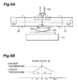
- Fig. 6A is a view showing the heating step in which the vicinity of the fused point 30 is heated with the micro torch 100 acting as heating means while the temperature distribution is monitored with the infrared-ray radiation thermometer 110
- Fig. 6B is a graph showing the temperature distribution in the vicinity of the fused point 30 monitored by the infrared-ray radiation thermometer 110.
- the first and second optical fibers 10, 20 may be partly heated in the heating step in this method such that the highest temperature is attained at a position separated by 1.0 mm or less (distance L) from the fused point 30 toward the first optical fiber 10 or second optical fiber 20 (Figs. 5A and 5B).
- the first and second optical fibers 10, 20 may be partly heated in the heating step in this method such that the highest temperature is attained at a position separated by 0.5 mm or less (distance L) from the fused point 30 toward the first optical fiber 10 or second optical fiber 20 (see Figs. 6A and 6B).
- the temperature distribution of the first and second optical fibers 10, 20 in the vicinity of the fused point 30 is set appropriately in the heating step.
- the temperature distribution can be set as such when the structure of the heating source such as the micro torch 100 or electric heater, the flow rate of each gas supplied to the micro torch 100, the distance between the heating source and each optical fiber, and the like are adjusted.
- a noncontact type thermometer is favorably used for measuring the temperature distribution of each of the first and second optical fibers 10, 20 in the heating step.
- the infrared-ray radiation thermometer 110 is utilized.
- a magnifying lens 120 is disposed between the infrared-ray radiation thermometer 110 and the first and second optical fibers 10, 20.
- each of the first and second optical fibers 10, 20 is mainly composed of silica glass and has a columnar form
- the emissivity is set to 0.5.
- the heating source such as the micro torch 100 or electric heater
- the temperature distribution measured by an infrared-ray radiation thermometer has such a form that the temperature monotonously decreases toward both side from the position at which the temperature attains the maximum value.
- the highest heating temperature at the time of heating is required to be such a temperature that the main ingredient of the first and second optical fibers 10, 20 is not softened.
- the surface temperature measured by the infrared-ray radiation thermometer 110 at each position of the first and second optical fibers 10, 20 is needed to be about 1300°C or less.
- the heating temperature for a region to enhance the mode field diameter (in the vicinity of the fused point 30) in the first and second optical fibers 10, 20 is required to be a temperature at which dopants added to the first and second optical fibers 10, 20 can disperse. Namely, when the dopants are Ge and F, the surface temperature measured by the infrared-ray radiation thermometer 110 in the heating region in the first and second optical fibers 10, 20 is needed to be about 500°C or higher.
- the optical fiber device 1 obtained by way of the foregoing heating step can easily satisfy any of the conditions of expressions (1A) to (1F), (2A) to (2D), and (4A) and (4B) when the difference between the respective mode field diameters D 10 , D 20 of the first and second optical fibers 10, 20 before fusion-splicing is 2 ⁇ m or greater, and any of the conditions of expressions (3A) to (3D) and (5A) and (5B) when the difference between the respective mode field diameters D 10 , D 20 of the first and second optical fibers 10, 20 before fusion-splicing is 2 ⁇ m or less.
- optical fiber device 1 whether the mode field diameter is enhanced in the vicinity of the fused point 30 between the first and second optical fibers 10, 20 or not, i.e., dopants are dispersed or not, can be verified by the following FFP method (Katsuhiko Okubo, "Optical Fiber Technology in ISDN Era,” Rikogakusha, Chapter 3, 3-10 to 3-11). Namely, at the position separated from the fusedpoint 30 by a distance L, each of the first and second optical fibers 10, 20 is cut, near-field patterns of light emitted from thus cut end faces are measured, and respective mode field diameters D 1 (L), D 2 (L) at the end faces are determined according to the near-field patterns.
- each of the optical fibers 10, 20 is repeated while the value of distance L is gradually increased, and the mode field diameters D 1 (L), D 2 (L) at thus cut end faces are successively determined, whereby the ratio of change inmode fielddiameter is obtained.
- the distribution of each dopant in the cut end face is analyzed by EPMA and the like, whereby it can be seen according to results of analysis whether the dopant is dispersed or not.
- optical fiber device according to the present invention and the method of making the same will now be explained.
- the optical fiber device comprises first and second optical fibers 10, 20 in which the difference between mode field diameters D 10 , D 20 before fusion-splicing is 2 ⁇ m or greater, i.e., D 10 - D 20 ⁇ 2 ⁇ m .
- a predetermined region including the fused point 30 between the first and second optical fibers 10, 20 is heated with a micro torch (see Fig. 5A), whereby the optical fiber device according to the first embodiment is obtained.
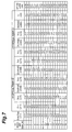
- Fig. 7 is a table listing various items mentioned above concerning sample Nos. 1 to 18 corresponding to the optical fiber device according to the first embodiment. Successively from the left side, the table of Fig. 7 shows sample No., and the mode field diameters D 1 (0) and D 2 (0) at the fused point 30.
- the table shows the splice loss at the fused point 30.
- the splice loss of the optical fiber device according to the first embodiment is suppressed to 0.2 dB or less in general when the above-mentioned conditions of expressions (1A) to (1F), (2A) to (2D), or (4A) and (4B) are satisfied.
- the optical fiber device comprises first and second optical fibers 10, 20 in which the difference between mode field diameters D 10 , D 20 before fusion-splicing is 2 ⁇ m or less, i.e., 0 ⁇ D 10 - D 20 ⁇ 2 ⁇ m .
- a predetermined region including the fused point 30 between the first and second optical fibers 10, 20 is heated with a micro torch (see Fig. 6A), whereby the optical fiber device according to the second embodiment is obtained.
- the inventors determined mode field diameters D 1 (0), D 2 (0), D 1 (1), and D 2 (1), the distance L at which the value of D 1 ( L )- D 10 becomes 0.1 ⁇ m or less, and the distance L at which the value of D 2 ( L )- D 20 becomes 0.1 ⁇ m or less.
- the table shows the splice loss at the fused point 30.
- the splice loss of the optical fiber device according to the second embodiment is suppressed to 0.2 dB or less in general when the above-mentioned conditions of expressions (3A) to (3D) or (5A) and (5B) are satisfied.
- the optical fiber device comprises first and second optical fibers 10, 20 in which the difference between mode field diameters D 10 , D 20 before fusion-splicing is 2 ⁇ m or greater, i.e., D 10 - D 20 ⁇ 2 ⁇ m .
- a predetermined region including the fused point 30 between the first and second optical fibers 10, 20 is heated with a micro torch (see Fig. 5A), whereby the optical fiber device according to the third embodiment is obtained.
- a propane gas and an oxygen gas are supplied to the micro torch.
- the inventors determined a temperature distribution in the vicinity of the fused point 30 between the first and second optical fibers 10, 20 by using an infrared-ray radiation thermometer at the time of heating with the micro torch. After the completion of the heating step, the inventors measured the splice loss at the fused point 30.
- the optical fiber device comprises first and second optical fibers 10, 20 in which the difference between mode field diameters D 10 , D 20 before fusion-splicing is 2 ⁇ m or less, i.e., 0 ⁇ D 10 - D 20 ⁇ 2 ⁇ m .
- a predetermined region including the fused point 30 between the first and second optical fibers 10, 20 is heated with a micro torch (see Fig. 6A), whereby the optical fiber device according to the fourth embodiment is obtained.
- a propane gas and an oxygen gas are supplied to the micro torch.
- the inventors determined a temperature distribution in the vicinity of the fused point 30 between the first and second optical fibers 10, 20 by using an infrared-ray radiation thermometer at the time of heating with the micro torch. After the completion of the heating step, the inventors measured the splice loss at the fused point 30.
- the optical fiber device comprises first and second optical fibers 10, 20 in which the difference between mode field diameters D 10 , D 20 before fusion-splicing is 2 ⁇ m or greater, i.e., D 10 - D 20 ⁇ 2 ⁇ m .
- a predetermined region including the fused point 30 between the first and second optical fibers 10, 20 is heated with a micro torch (see Fig. 5A), whereby the optical fiber device according to the fifth embodiment is obtained.
- a propane gas and an oxygen gas are supplied to the micro torch.
- the optical fiber device comprises first and second optical fibers 10, 20 in which the difference between mode field diameters D 10 , D 20 before fusion-splicing is 2 ⁇ m or less, i.e., 0 ⁇ D 10 - D 20 ⁇ 2 ⁇ m .
- a predetermined region including the fused point 30 between the first and second optical fibers 10, 20 is heated with a micro torch (see Fig. 6A), whereby the optical fiber device according to the sixth embodiment is obtained.
- a propane gas and an oxygen gas are supplied to the micro torch.
- the optical fiber device comprises first and second optical fibers 10, 20 in which the difference between mode field diameters D 10 , D 20 before fusion-splicing is 2 ⁇ m or greater, i.e., D 10 - D 20 ⁇ 2 ⁇ m .
- a predetermined region including the fused point 30 between the first and second optical fibers 10, 20 is heated with an electricheater (see Fig. 5A), whereby the optical fiber device according to the seventh embodiment is obtained.
- samples were manufactured by any of a heating step in which the vicinity of the fused point 30 was heated such that the difference between the highest and lowest temperatures in a region having a length of 4 mm centered at the fused point 30 became 100°C or less as in the third embodiment and a heating step in which the vicinity of the fused point 30 was heated such that the highest temperature was attained at a position separated by 1 mm or less from the fused point 30 as in the fifth embodiment.
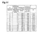
- Fig. 13 is a table listing the surface temperature and splice loss of each part concerning sample Nos. 1 to 4 for which the heating step was carried out as in the third embodiment as the optical fiber device according to the seventh embodiment.
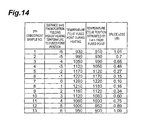
- Fig. 14 is a table listing the surface temperature and splice loss of each part concerning sample Nos. 5 to 17 for which the heating step was carried out as in the fifth embodiment as the optical fiber device according to the seventh embodiment.
- the splice loss is suppressed to 0.2 dB or less in general if the difference between the highest and lowest temperatures in the region having a length of 4 mm centered at the fused point 30 during heating is 100°C or less (sample Nos. 1 to 4) in the case where the electric heater is utilized as in the case utilizing the micro torch. Also, the splice loss is suppressed to 0.2 dB or less in general if the highest temperature is attained at a position where the distance L from the fused point 30 is 1.0 mm or less (sample Nos. 5 to 17).
- the respective ratios of change in the mode field diameters D 1 (L) and D 2 (L) of the first and second optical fibers after fusion-splicing are set appropriately according to the difference between the mode field diameters D 10 , D 20 (minimum values) of the first and second optical fibers before fusion-splicing, whereby the splice loss at the fused point between the first and second optical fibers can effectively be reduced.
Landscapes
- Physics & Mathematics (AREA)
- Engineering & Computer Science (AREA)
- Plasma & Fusion (AREA)
- General Physics & Mathematics (AREA)
- Optics & Photonics (AREA)
- Mechanical Coupling Of Light Guides (AREA)
- Optical Fibers, Optical Fiber Cores, And Optical Fiber Bundles (AREA)
Applications Claiming Priority (2)
| Application Number | Priority Date | Filing Date | Title |
|---|---|---|---|
| JP2000321687 | 2000-10-20 | ||
| JP2000321687A JP2002131558A (ja) | 2000-10-20 | 2000-10-20 | 光ファイバ素子およびその製造方法 |
Publications (2)
| Publication Number | Publication Date |
|---|---|
| EP1237018A2 true EP1237018A2 (fr) | 2002-09-04 |
| EP1237018A3 EP1237018A3 (fr) | 2004-04-28 |
Family
ID=18799765
Family Applications (1)
| Application Number | Title | Priority Date | Filing Date |
|---|---|---|---|
| EP01124296A Withdrawn EP1237018A3 (fr) | 2000-10-20 | 2001-10-18 | Dispositif à fibre optique et son procédé de fabrication |
Country Status (4)
| Country | Link |
|---|---|
| US (1) | US6817784B2 (fr) |
| EP (1) | EP1237018A3 (fr) |
| JP (1) | JP2002131558A (fr) |
| AU (1) | AU777348B2 (fr) |
Cited By (2)
| Publication number | Priority date | Publication date | Assignee | Title |
|---|---|---|---|---|
| WO2004046778A3 (fr) * | 2002-11-20 | 2004-07-08 | Vytran Corp | Procede et dispositif pour former des epissures presentant de faibles pertes optiques |
| WO2005026797A1 (fr) * | 2003-09-18 | 2005-03-24 | Telefonaktiebolaget Lm Ericsson (Publ) | Fusion splicing of optical fibres having mismatched mode field diameters |
Families Citing this family (7)
| Publication number | Priority date | Publication date | Assignee | Title |
|---|---|---|---|---|
| JP2002277672A (ja) * | 2001-03-13 | 2002-09-25 | Viveen Ltd | 光ファイバー結合体 |
| KR20050042921A (ko) * | 2003-11-04 | 2005-05-11 | 한국전자통신연구원 | 브라그 격자를 갖는 광섬유 및 그 제조방법 |
| US6830386B1 (en) | 2004-04-28 | 2004-12-14 | Corning Incorporated | Optical transmission line and method of manufacture |
| JP5761235B2 (ja) * | 2013-03-06 | 2015-08-12 | 横河電機株式会社 | 光ファイバ温度分布測定装置 |
| EP3757635B1 (fr) * | 2018-02-20 | 2023-10-25 | Sumitomo Electric Industries, Ltd. | Procédé de fabrication de fibre optique |
| WO2020040220A1 (fr) * | 2018-08-24 | 2020-02-27 | 住友電気工業株式会社 | Ligne de fibre optique, module et procédé de fabrication de ligne de fibre optique |
| CN111175908A (zh) * | 2020-01-21 | 2020-05-19 | 华为技术有限公司 | 一种光纤连接结构和光纤连接组件 |
Citations (2)
| Publication number | Priority date | Publication date | Assignee | Title |
|---|---|---|---|---|
| JPH10300970A (ja) * | 1997-04-24 | 1998-11-13 | Sumitomo Electric Ind Ltd | 光ファイバ素子及び光ファイバ接続方法 |
| JP2000098171A (ja) * | 1998-09-25 | 2000-04-07 | Fujikura Ltd | 光ファイバの融着接続方法 |
Family Cites Families (11)
| Publication number | Priority date | Publication date | Assignee | Title |
|---|---|---|---|---|
| JP2693649B2 (ja) * | 1991-02-15 | 1997-12-24 | 日本電信電話株式会社 | 光ファイバのモードフィールド径拡大装置 |
| JP2771737B2 (ja) * | 1992-07-01 | 1998-07-02 | 日本電信電話株式会社 | コア拡大光ファイバの作製方法 |
| US5802224A (en) * | 1994-05-23 | 1998-09-01 | Kyocera Corporation | Optical coupler for performing light branching and light mixing/branch filtering in a light communication network |
| JP3497298B2 (ja) * | 1995-10-23 | 2004-02-16 | 株式会社フジクラ | 光ファイバフィルタ |
| SE511966C2 (sv) * | 1997-06-09 | 1999-12-20 | Ericsson Telefon Ab L M | Förfarande och anordning för att hopskarva ändarna hos två optiska fibrer av olika typ med varandra |
| US6275627B1 (en) * | 1998-09-25 | 2001-08-14 | Corning Incorporated | Optical fiber having an expanded mode field diameter and method of expanding the mode field diameter of an optical fiber |
| JP4104769B2 (ja) * | 1999-02-25 | 2008-06-18 | 株式会社フジクラ | 光ファイバ融着接続装置 |
| JP2002072006A (ja) * | 2000-08-28 | 2002-03-12 | Sumitomo Electric Ind Ltd | 光ファイバの接続方法 |
| US6565269B2 (en) * | 2001-02-07 | 2003-05-20 | Fitel Usa Corp. | Systems and methods for low-loss splicing of optical fibers having a high concentration of fluorine to other types of optical fiber |
| JP4617587B2 (ja) * | 2001-03-22 | 2011-01-26 | 住友電気工業株式会社 | 光ファイバ伝送路 |
| JP2002365466A (ja) * | 2001-06-05 | 2002-12-18 | Sumitomo Electric Ind Ltd | 光ファイバ接続方法 |
-
2000
- 2000-10-20 JP JP2000321687A patent/JP2002131558A/ja active Pending
-
2001
- 2001-10-04 AU AU78232/01A patent/AU777348B2/en not_active Ceased
- 2001-10-16 US US09/977,348 patent/US6817784B2/en not_active Expired - Lifetime
- 2001-10-18 EP EP01124296A patent/EP1237018A3/fr not_active Withdrawn
Patent Citations (2)
| Publication number | Priority date | Publication date | Assignee | Title |
|---|---|---|---|---|
| JPH10300970A (ja) * | 1997-04-24 | 1998-11-13 | Sumitomo Electric Ind Ltd | 光ファイバ素子及び光ファイバ接続方法 |
| JP2000098171A (ja) * | 1998-09-25 | 2000-04-07 | Fujikura Ltd | 光ファイバの融着接続方法 |
Non-Patent Citations (1)
| Title |
|---|
| SHIRAISHI KAZUO; YANAGI TAKUYA; KAWAKAMI SHOJIRO: "Light-propagation characteristics in thermally diffused expanded core fibers", JOURNAL OF LIGHTWAVE TECHNOLOGY, vol. 11, no. 10, October 1993 (1993-10-01), NEW YORK, USA, pages 1584 - 1591, XP000418376 * |
Cited By (2)
| Publication number | Priority date | Publication date | Assignee | Title |
|---|---|---|---|---|
| WO2004046778A3 (fr) * | 2002-11-20 | 2004-07-08 | Vytran Corp | Procede et dispositif pour former des epissures presentant de faibles pertes optiques |
| WO2005026797A1 (fr) * | 2003-09-18 | 2005-03-24 | Telefonaktiebolaget Lm Ericsson (Publ) | Fusion splicing of optical fibres having mismatched mode field diameters |
Also Published As
| Publication number | Publication date |
|---|---|
| EP1237018A3 (fr) | 2004-04-28 |
| US20020048437A1 (en) | 2002-04-25 |
| JP2002131558A (ja) | 2002-05-09 |
| US6817784B2 (en) | 2004-11-16 |
| AU777348B2 (en) | 2004-10-14 |
| AU7823201A (en) | 2002-05-02 |
Similar Documents
| Publication | Publication Date | Title |
|---|---|---|
| US6275627B1 (en) | Optical fiber having an expanded mode field diameter and method of expanding the mode field diameter of an optical fiber | |
| EP1488261B1 (fr) | Fibre optique a faible perte par courbure et composants fabriques a partir de cette derniere | |
| US6789960B2 (en) | Method of connecting optical fibers, an optical fiber therefor, and an optical fiber span therefrom | |
| US20180224607A1 (en) | Optical fiber for silicon photonics | |
| US6817784B2 (en) | Optical fiber device and method of making the same | |
| US6840687B2 (en) | Systems and methods for low-loss splicing of optical fibers | |
| US7037004B2 (en) | Optical fiber component for spot size transition and method of making the same | |
| JP2618500B2 (ja) | 光ファイバ接続方法 | |
| US6729777B2 (en) | Optical fiber splicing method and optical transmission line | |
| JP4675378B2 (ja) | 光伝送ライン及びその製造方法 | |
| US6644870B2 (en) | Optical fiber transmission line | |
| US11493690B2 (en) | Optical fiber line, module, and method for manufacturing optical fiber line | |
| US20020181904A1 (en) | Optical fiber splicing method and optical fiber | |
| US20040163419A1 (en) | Method and apparatus for forming low optical loss splices | |
| JP2004325863A (ja) | 光ファイバの接続方法及び接続部を有する光ファイバ | |
| CN101010608A (zh) | 宽带光纤分接器 |
Legal Events
| Date | Code | Title | Description |
|---|---|---|---|
| PUAI | Public reference made under article 153(3) epc to a published international application that has entered the european phase |
Free format text: ORIGINAL CODE: 0009012 |
|
| AK | Designated contracting states |
Kind code of ref document: A2 Designated state(s): AT BE CH CY DE DK ES FI FR GB GR IE IT LI LU MC NL PT SE TR |
|
| AX | Request for extension of the european patent |
Free format text: AL;LT;LV;MK;RO;SI |
|
| PUAL | Search report despatched |
Free format text: ORIGINAL CODE: 0009013 |
|
| AK | Designated contracting states |
Kind code of ref document: A3 Designated state(s): AT BE CH CY DE DK ES FI FR GB GR IE IT LI LU MC NL PT SE TR |
|
| AX | Request for extension of the european patent |
Extension state: AL LT LV MK RO SI |
|
| RIC1 | Information provided on ipc code assigned before grant |
Ipc: 7G 02B 6/38 A |
|
| 17P | Request for examination filed |
Effective date: 20040705 |
|
| AKX | Designation fees paid |
Designated state(s): DE DK FR GB IT |
|
| 17Q | First examination report despatched |
Effective date: 20060703 |
|
| STAA | Information on the status of an ep patent application or granted ep patent |
Free format text: STATUS: THE APPLICATION IS DEEMED TO BE WITHDRAWN |
|
| 18D | Application deemed to be withdrawn |
Effective date: 20061114 |