EP1236668B1 - Verfahren zum Anlegen eines Garnes an eine Spulhülse in einer automatischen Aufwickelmaschine und automatische Aufwickelmaschine - Google Patents
Verfahren zum Anlegen eines Garnes an eine Spulhülse in einer automatischen Aufwickelmaschine und automatische Aufwickelmaschine Download PDFInfo
- Publication number
- EP1236668B1 EP1236668B1 EP20020002723 EP02002723A EP1236668B1 EP 1236668 B1 EP1236668 B1 EP 1236668B1 EP 20020002723 EP20020002723 EP 20020002723 EP 02002723 A EP02002723 A EP 02002723A EP 1236668 B1 EP1236668 B1 EP 1236668B1
- Authority
- EP
- European Patent Office
- Prior art keywords
- yarn
- trapping
- winding
- leading member
- doffing
- Prior art date
- Legal status (The legal status is an assumption and is not a legal conclusion. Google has not performed a legal analysis and makes no representation as to the accuracy of the status listed.)
- Expired - Lifetime
Links
- 238000004804 winding Methods 0.000 title claims description 284
- 238000000034 method Methods 0.000 title claims description 42
- 238000005304 joining Methods 0.000 claims description 79
- 238000005520 cutting process Methods 0.000 claims description 10
- 230000032258 transport Effects 0.000 claims description 10
- 238000011144 upstream manufacturing Methods 0.000 claims description 2
- 230000007547 defect Effects 0.000 description 8
- 230000003028 elevating effect Effects 0.000 description 5
- 238000010586 diagram Methods 0.000 description 4
- 238000002360 preparation method Methods 0.000 description 3
- 239000011248 coating agent Substances 0.000 description 2
- 238000000576 coating method Methods 0.000 description 2
- 238000007599 discharging Methods 0.000 description 2
- 238000006073 displacement reaction Methods 0.000 description 2
- 230000000694 effects Effects 0.000 description 2
- 238000004018 waxing Methods 0.000 description 2
- 230000035515 penetration Effects 0.000 description 1
Images


Classifications
-
- B—PERFORMING OPERATIONS; TRANSPORTING
- B65—CONVEYING; PACKING; STORING; HANDLING THIN OR FILAMENTARY MATERIAL
- B65H—HANDLING THIN OR FILAMENTARY MATERIAL, e.g. SHEETS, WEBS, CABLES
- B65H54/00—Winding, coiling, or depositing filamentary material
- B65H54/02—Winding and traversing material on to reels, bobbins, tubes, or like package cores or formers
- B65H54/22—Automatic winding machines, i.e. machines with servicing units for automatically performing end-finding, interconnecting of successive lengths of material, controlling and fault-detecting of the running material and replacing or removing of full or empty cores
- B65H54/26—Automatic winding machines, i.e. machines with servicing units for automatically performing end-finding, interconnecting of successive lengths of material, controlling and fault-detecting of the running material and replacing or removing of full or empty cores having one or more servicing units moving along a plurality of fixed winding units
-
- B—PERFORMING OPERATIONS; TRANSPORTING
- B65—CONVEYING; PACKING; STORING; HANDLING THIN OR FILAMENTARY MATERIAL
- B65H—HANDLING THIN OR FILAMENTARY MATERIAL, e.g. SHEETS, WEBS, CABLES
- B65H65/00—Securing material to cores or formers
-
- B—PERFORMING OPERATIONS; TRANSPORTING
- B65—CONVEYING; PACKING; STORING; HANDLING THIN OR FILAMENTARY MATERIAL
- B65H—HANDLING THIN OR FILAMENTARY MATERIAL, e.g. SHEETS, WEBS, CABLES
- B65H67/00—Replacing or removing cores, receptacles, or completed packages at paying-out, winding, or depositing stations
- B65H67/04—Arrangements for removing completed take-up packages and or replacing by cores, formers, or empty receptacles at winding or depositing stations; Transferring material between adjacent full and empty take-up elements
-
- B—PERFORMING OPERATIONS; TRANSPORTING
- B65—CONVEYING; PACKING; STORING; HANDLING THIN OR FILAMENTARY MATERIAL
- B65H—HANDLING THIN OR FILAMENTARY MATERIAL, e.g. SHEETS, WEBS, CABLES
- B65H2701/00—Handled material; Storage means
- B65H2701/30—Handled filamentary material
- B65H2701/31—Textiles threads or artificial strands of filaments
Definitions
- the present invention relates to a yam setting method and an automatic winder according to the preamble of claim 1 and 9, respectively.
- a known yam setting method for a winding tube in an automatic winder is such that under the state in which the yarn is connected between the yarn supplying body and a yarn winding body, a doffing device picks up and cuts the connected yarn and traps the lower yarn leading to the yarn supplying body, discharges the yarn winding body, and sets a new winding tube at the same time as the setting of the trapped yarn of the yarn supplying body to the winding tube.
- the upper yarn trapped by the suction pipe and the lower yarn trapped by the relay pipe are led into a yarn joining device respectively, the yarn is joined.
- a state in which the yarn is connected from the yarn supplying body to the yarn winding body is created.
- the position to pick up the lower yarn is located in the lower part of a winding unit and away from the position of the doffing device. Therefore, the accuracy in the position of the yarn picking lever to be advanced from the doffing device to the lower direction is required to be high, and the time required for the yarn picking lever to advance to the lower direction also becomes long.
- the present invention was made in consideration to aforementioned problems and it is thus the object of the present invention to provide a yarn setting method for the winding tube in an automatic winder and an automatic winder capable of carrying out the setting operation of the yarn of the yarn supplying body smoothly and speedily.
- the doffing device Since the moving of the lower yarn to the yarn winding body side by the lower yarn trapping-leading member at the winding unit side is completed before the doffing device arrives at the winding unit, the doffing device is capable of starting the picking operation of the lower yarn immediately after arriving at the winding unit, and as a result, the time required for setting the yarn to the winding tube can be shortened.
- the lower yarn When the yarn winding body becomes full and the yarn is cut, the lower yarn may be held by the holding means temporarily, and then the lower yarn is trapped by the lower yarn trapping-leading member. As a result, the lower yarn can be held by the lower yarn trapping-leading member reliably.
- a tension applying device for applying tension to the yarn may also serve as a holding means for holding the lower yarn after the yarn is cut. Therefore, a separate suction-typed yarn trap or the like for holding the yarn when the yarn is cut is not required.
- the lower yarn trapping-leading member may be on standby under the state in which the lower yarn trapping mouth is facing downward at the yam supplying body side of the yarn joining device during winding, and the yarn trapping by the lower yarn trapping-leading member can be carried out speedily after the yarn is cut. Since the yarn held by the holding means is trapped by the lower yarn trapping-leading member being moved from the downward state to the yarn trapping position, a separate movable guide for guiding the yarn held by the holding means to the lower yarn trapping-leading member is not required. As a result, the structure can be simple.
- the lower yarn trapping-leading member may include a clamp device and be stopped before the leading position for leading into the yarn joining device, the demand signal can be transmitted while the clamp device is under the clamping state, and the yarn of the yarn supplying body is not drawn out excessively.
- a first driving means may be available exclusive for the lower yarn trapping-leading member, when the yarn winding body becomes full and a doffing is demanded, without operating unnecessary members including the upper yarn trapping-leading member, only the lower yarn trapping-leading member can be operated. Therefore, the trapping of the lower yarn after the yarn is cut and the lifting of the trapped lower yarn to the yarn winding body can be carried out speedily, and the doffing demand can be transmitted in early stage after the yarn winding body becomes full.
- a stepping motor is used for the first driving means, according to the control pulse number, the lower yarn trapping-leading member can be stopped at any position reliably.
- the upper yarn trapping-leading member and the yarn joining device may be prohibited, the upper yarn is not drawn out from the yarn winding body and the yarn joining is not carried out, and only the moving of the lower yarn to the yarn winding body side by the lower yarn trapping-leading member is carried out.
- the yarn winding body is not rotated, and the yarn leading to the yarn winding body is not trapped by the upper yarn trapping-leading member.
- the yarn joining device is prevented from working on the lower yarn, and in addition, the position where the lower yarn trapping-leading member is stopped, is located immediately in front of the position where the yarn is led to the yarn joining device, and the lower yarn trapping-leading member is capable of transporting up the lower yarn to the highest position.
- the upper yarn sucking-leading member Only by lifting the yarn winding body from the driving drum by the lifting means, the upper yarn sucking-leading member becomes non-acting, and by the pausing means for the driving means of the upper yarn sucking-leading member and the lower yarn sucking-leading member, the lower yarn is led to a position higher than the yarn joining device by the lower yarn sucking-leading member.
- the upper yarn trapping-leading member and the lower yarn trapping-leading member can be paused per each winding unit.
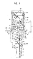
- an automatic winder 1 comprises winding units 2 and a doffing device 3 capable of running along the winding units 2.
- Each winding unit 2 winds a yarn Y from one or more yarn supplying body 5 and forms a large yarn winding body 6.
- the yarn Y unwound from the supply bobbin 5 supported by a tray 11 is wound up to the yarn winding body 6 which is held by a cradle 12 and rotated by a traverse drum 13.
- an unwinding assisting device 15 for assisting the unwinding of the yarn Y from the supply bobbin 5
- a gate-typed tension applying device (which serves also as lower yarn holding means) 16 for applying a designated tension to the yarn Y
- a yarn joining device 20 for applying a designated tension to the yarn Y
- a yarn joining device 20 for applying a designated tension to the yarn Y
- a yarn joining device 20 for applying a designated tension to the yarn Y
- a yarn joining device 20 for applying a designated tension to the yarn Y
- a yarn joining device 20 for applying a designated tension to the yarn Y
- a yarn joining device 20 for applying a designated tension to the yarn Y
- a yarn joining device 20 for applying a designated tension to the yarn Y
- a yarn joining device 20 for applying a designated tension to the yarn Y
- a yarn joining device 20 for applying a designated tension to the yarn Y
- a yarn joining device 20 for applying a designated tension to the yarn Y
- a contacting-typed tension applying device for applying tension by the friction with the yarn for example, a gate-typed tension applying device which engages a pair of comb-blades, or the disk-typed tension applying device for applying tension by sandwiching the yarn between a pair of disks.
- the tension applied by the tension applying device 16 can be adjusted by an electric signal.
- the tension applying device 16 in the case the tension applying device 16 is the gate-typed and the comb-blades are completely engaged, the tension applying device 16 can hold the yarn.
- the tension applying device 16 is a disk-typed, by raising the pressuring force between the disks, the yarn can be held.
- an air-typed yarn joining device for joining the yarn by jetting a whirling air flow to the overlapping section of both yarn ends is preferable to be used.
- a pivotable suction pipe 21 (an embodiment of the upper yarn trapping-leading member) which sucks and traps the yarn from the yarn winding body 6 (hereafter referred to as "upper yarn”) and then leads it into the yarn joining device 20 is provided above the yarn joining device 20.
- a pivotable relay pipe 22 (an embodiment of the lower yarn trapping-leading member) sucks and traps the yarn at the yarn supplying body 5 side which is connected to the yarn supplying body 5 (hereafter referred to as "lower yarn”) and leads it into the yarn joining device 20.
- a lower yarn trapping mouth 22a for sucking and trapping the lower yarn, and a clamp device 22b for switching the lower yarn trapping mouth 22a between closed state and opened state and clamping the lower yarn under the closed state are provided.
- the relay pipe 22 is turned in the vertical direction by a stepping motor 49, and by the control of the stepping motor 49, the relay pipe 22 can be located at a lower end (yarn end trapping) position (a), a standby position (b) which is the downward state below the yarn joining device 20, a doffing standby position (c) which is the upward state above the yarn joining device 20, and an upper end position (d) above the yarn joining device 20.
- the clamp device 22b switches from the closed state to the opened state by hitting a stopper at the yarn end trapping position (a) or the upper end position (d).
- the relay pipe 22 sucks the lower yarn from the lower yarn trapping mouth 22a at the lower end position (a), and releases the clamped yarn end at the upper end position (d).
- the clamp device 22b is maintained under the closed state at the position other than the lower end position (a) or the upper end position (d), and the trapped lower yarn is kept being clamped.
- the suction pipe 21 is coordinately driven with the yarn joining device 20 via a driving motor 46 and a cam mechanism 45. Moreover, the suction pipe 21 can be located at the downward standby position where the upper yarn trapping mouth is located below the yarn joining device 20, and the upward yarn trapping position where the upper yarn trapping mouth is located in the proximity to the position where the yarn winding body 6 and the traverse drum 13 are contacting each other.
- the yarn end of the yarn supplying body 5 is blown up, and the yarn end reaches a yarn guide 23 via the unwinding assisting device 15, and is sucked and trapped by the lower yarn trapping mouth 22a of the relay pipe 22 which is located at the lower end position (a).
- the relay pipe 22 moves from the standby position (b) to the lower end position (a), the clamp device 22b opens, and by the suction from the lower yarn trapping mouth 22a, the yarn end at the yarn supplying body 5 side held by the tension applying device 16 is sucked and trapped to the relay pipe 22.
- the suction pipe 21 turns along the arrow, upward from the solid line position shown to the upward yarn trapping position, and sucks and traps the yarn end of the yarn winding body 6 rewound by the rotating in the reverse direction to the winding direction of the traverse drum 13. Then, when the suction pipe 21 turns downward to the solid line position shown in the drawings (downward standby position), and the relay pipe 22 moves to the upper end position (d), both the lower yarn and the upper yarn are led to the yarn joining device 20, the lower yarn and the upper yarn are joined by the yarn joining device 20.
- the traverse drum 13 is rotatable in the winding direction or in the reverse direction by the driving motor 25.
- a traverse groove is formed on the surface of the traverse drum 13, and the yarn Y to be wound up along the traverse groove carries out the traverse operation.
- the yarn winding body 6 moving with the traverse drum 13 is held by the cradle 12.
- the cradle 12 By the operation of an arm 12a, the cradle 12 is capable of being opened and closed in the depth direction of the page of Figure 1, and the releasing of the full tube and the setting of a new winding tube are also made practicable.
- the cradle 12 which is holding the yarn winding body 6 can be lifted for a designated interval from the traverse drum 13 by a cradle lifter 26.
- a package brake 27 for stopping the rotating of the yarn winding body 6 which has become free by being lifted is provided at the tip of the cradle 12.
- the yarn winding body 6 released from the cradle 12 is discharged to a transporting device 29 such as a belt conveyor via a package guide 28.
- the transporting device 29 is provided on the back side of the winding unit 2, along the winding units 2.
- the package guide 28 is capable of interlocking with the cradle 12, and when the cradle 12 elevates, the package guide 28 inclines toward the direction to be discharged.
- a winding tube accumulating device 4 is provided above the cradle 12 of each winding unit 2, and a winding tube 7 received from the winding tube accumulating device 4 is set to the cradle 12 by the doffing device 3.
- the doffing device 3 comprises a yarn picking lever 31, a yarn shifting lever 32, an opener 34 and a chucker 35.
- the yarn picking lever 31 traps the lower yarn of the winding unit 2 and sets the lower yarn y2 to the winding tube 7 which is set to the cradle 12.
- the yarn shifting lever 32 sets the lower yarn to the winding tube 7 by interlocking with the yarn picking lever 31 and applying a bunch winding.
- the opener 34 carries out the releasing and closing operation to the arm 12a of the cradle 12.
- the chucker 35 clamps the winding tube 7 from the winding tube accumulating device 4 and transports the winding tube 7 to the cradle 12.
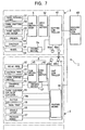
- each winding unit 2 comprises a unit controller 41 respectively
- the doffing device 3 comprises a doffing controller 42
- a plurality of unit controllers 41 and the doffing controller 42 are both connected to a machine body controller 43 via communication network.
- a doffing demand signal transmitted from the unit controller 41 can be transmitted to the doffing controller 42 via the machine body controller 43.
- the machine body controller 43 is provided at the end section of the machine body to control over the entire machine body, and is capable of transmitting various setting values from the machine body controller 43 to the unit controller 41 and the doffing controller 42 via the communication network.
- the stepping motor 49 for turning the relay pipe 22, the driving motor 46 for rotating a cam mechanism 45 for operating the yarn joining device 20 and the suction pipe 21, and a driving motor 47 for rotating and driving the traverse drum 13 are connected to the unit controller 41 of the winding unit 2.
- a pausing means 48 is provided for stopping the relay pipe 22 at the doffing standby position (c) for waiting for the doffing by being located at the position immediately before the upper end position (d).
- the unit controller 41 receives a yarn defect signal from the yarn clearer 19, transmits the yarn cutting signal to the cutter 19a, carries out elevating or descending control of the cradle lifter 26, and carries out the on-off control of the package brake 27.
- a driving motor 52 for rotating and driving a cam mechanism 51 which operates the yarn picking lever 31, the yarn shifting lever 32, the opener 34 and the chucker 35 and a driving motor 54 for rotating and driving a wheel 53 for running the doffing device 3 along a plurality of winding units 2, are connected to the doffing controller 42 of the doffing device 3.
- the winding unit 2 When the yarn winding body 6 of the winding unit 2 becomes a full tube, the winding unit 2 carries out a designated operation to be mentioned below, and after moving the relay pipe 22 which traps the lower yarn, to the doffing standby position (c), transmits a doffing demand signal to the doffing device 3.
- the doffing demand signal includes a unit number of the winding unit 2.
- the winding unit 2 lights a doffing demand lamp 55b recognizable by operators.
- the doffing demand signal is transmitted from the unit controller 41 to the doffing controller 42 via the machine body controller 43.
- the doffing device 3 runs toward the winding unit 2 which transmits the doffing demand signal, and stops directly above the winding unit 2.
- communicating means 56a, 56b can emit and receive infrared rays.
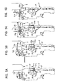
- Figure 4 shows the procedure to be carried out before the winding unit 2 transmits the doffing demand signal.
- Figure 5 shows the procedure which the winding unit 2 and the doffing device 3 carry out jointly.
- the cradle lifter 26 and the package brake 27 are operated, and the rotation of the yarn winding body 6 is stopped under the state in which the yarn winding body 6 is being lifted a little from the traverse drum 13. Then, the cradle lifter 26 is released and the yarn winding body 6 returns to a state in which it contacts the traverse drum 13.
- the relay pipe 22 turns to the lower end position (a) from the downward standby position (b).
- the clamp device 22b which is provided in the lower yarn trapping mouth 22a of the relay pipe 22 opens by hitting the yarn guide 23 which is a stopper and the lower yarn y2 is sucked and trapped by the lower yarn trapping mouth 22a between the tension applying device 16 and the yarn supplying body 5.
- the relay pipe 22 while trapping the lower yarn y2, turns to the doffing standby position (c) where the lower yarn trapping mouth 22a facing upward at the yarn winding body 6 side is above the yarn joining device 20.
- the relay pipe 22 stops temporarily at the doffing standby position (c) which is located immediately before the upper end position (d) above the yarn joining device 20, while the clamp device 22b is still clamping the lower yarn y2.
- the doffing demand signal is transmitted from the unit controller 41 of the winding unit 2 to the doffing controller 42 of the doffing device 3 via the machine body controller 43.
- the doffing device 3 which received the doffing demand signal stops directly above the winding unit 2 (Fig. 5A), swings the yarn picking lever 31 to the proximity of the winding unit 2.
- the cutter and holding unit 31a is advanced to the lower yarn y2 trapped by the relay pipe 22, and by holding the lower yarn y2 at the same time it is cut, and the lower yarn y2 is trapped by the yarn picking lever 31.
- the winding unit 2 transmits the doffing demand signal to call for the doffing device 3. Therefore, even when the doffing device 3 is located nearby the winding unit 2 by chance and arrives instantly, the turning operation of the relay pipe 22 and the yarn picking lever 31 do not interfere with each other.
- the opener 34 lifts up while opening the arm 12a of the cradle 12.
- the package guide 28 also inclines and the yarn winding body 6 released from the cradle 12 is discharged reliably via the package guide 28 onto the belt conveyor 29.
- the cradle 13 descends toward the traverse drum 13 while being opened, and is located at a position capable of setting the winding tube 7.
- the cradle 12 can be descended so as to open again at the end of the descending, after being closed once while descending.
- the chucker 35 clamps the winding tube 7 received from the winding tube supplying device, and transports it onto the traverse drum 13.
- the winding tube 7 is set in the bobbin holder of the cradle 12.
- the yarn picking lever 31 elevates and while elevating, threads the lower yarn y2 to the yarn shifting lever 32, and the lower yarn y2 crosses over between the opened cradle 12 and the winding tube 7, and between the cutter 31a of the yarn picking lever 31 and the yarn shifting lever 32.
- the opener 34 closes the cradle 12
- the lower yarn y2 is sandwiched at the edge of the winding tube 7 to be set.
- the package brake 27 is operated for a moment, and the displacement between the winding tube 7 and the bobbin holder is corrected.
- the doffing device 3 transmits the signal to the winding unit 2 via the communicating means 56a, 56b, the traverse drum 13 is rotated slowly, and a bunch winding is formed at the edge of the winding tube 7. Then, by rotating the traverse drum 13 at a high speed, the winding of the yarn of the yarn supplying body 5 is recommenced. After turning and moving the relay pipe 22 to the upper end position (d) in Figure 5B, until the winding is restarted in Figure 5D, the relay pipe 22 is completely returned to the standby position (b).
- the starting yarn attachment is an operation carried out by supplying the first yarn supplying body 5 to the winding position, under the state in which no yarn winding body 6 is located in the cradle 12.
- the yarn supplying body 5 is supplied to the winding position of the winding unit 2. At the time being, the yarn end of the yarn supplying body 5 is hanging down inside the core tube.
- the relay pipe 22 turns a little from the downward standby position (a) to the standby position (b). Then, the clamp device 22b hits the stopper and opens, and the lower yarn trapping mouth 22a is released. Under this state, the yarn end of the yarn supplying body 5 is blown up toward the upper part, and the relay pipe 22 traps the yarn end. Then, the relay pipe 22 turns to the doffing standby position (c), and stops temporarily. Under this state, the doffing demand signal is transmitted from the unit controller 41 of the winding unit 2 to the doffing controller 42 of the doffing device 3 via the machine body controller 43.
- the doffing device 3 which received the doffing demand signal stops directly above the winding unit 2, the yarn picking lever 31 is extended to the lower side to pick up the yarn which is trapped by the relay pipe 22.
- the cutter and holding unit 31a of the tip of the yarn picking lever 31 receives the yarn from the relay pipe 22, the relay pipe 22 turns to the upper end position (d), and the clamp device 22b opens to suck the remaining yarn end after the yarn cut.
- the discharging operation of the yarn winding body 6 is carried out in which the arm 12a of the cradle 12 is lifted while being opened. However, since there is no yarn winding body 6 held by the cradle 12 at the starting yarn attachment, no yarn winding body 6 is discharged actually.
- the cradle 12 descends while being opened, and reaches a position capable of setting the winding tube 7. Then, the chucker 35 clamps the winding tube 7 which is received from the winding tube supplying device, and transports it onto the traverse drum 13. The winding tube 7 is set between the bobbin holders of the cradle 12.
- the yarn picking lever 31 elevates, and threads the lower yarn y2 to the yarn shifting lever 32 while elevating, and between the cutter 31a of the yarn picking lever 31 and the yarn shifting lever 32, the lower yarn y2 is made to cross over between the cradle 12 which is in the opened state, and the winding tube 7.
- the opener 34 closes the cradle 12
- the lower yarn y2 is sandwiched on the edge of the winding tube 7.
- the package brake 27 is operated for a moment, and the displacement between the winding tube 7 and the bobbin holder is corrected.
- the doffing device 3 transmits a signal to the winding unit 2 via the communicating means 56a, 56b, the traverse drum 13 is rotated slowly, a bunch winding is formed at the edge of the winding tube 7, and then, by rotating the traverse drum 13 at a high speed, the winding of the yarn of the yarn supplying body 5 is recommenced. Further, after turning to the upper end position (d) and before recommencing the winding, the returning of the relay pipe 22 to the standby position which is a downward state is completed.
- the first embodiment described above has the following effects.
- the automatic winder 1 comprises winding units 2, and the doffing device 3 capable of running along the winding units 2 and in the depth direction of the page.
- the second embodiment for the members having the same function as with the first embodiment, same reference signs are used.
- the winding unit 2 winds the yarn from the yarn supplying bobbins 5 and forms the yarn winding body 6.
- the yam Y unwound from the yarn supplying body 5 supported by the tray 11 is held by the cradle 12 and wound to a yarn winding body 6 which moves along with the traverse drum 13.
- the winding unit 2 is constructed with the unwinding assisting device 15 for assisting the unwinding of the yarn from the yarn supplying body 5, the tension applying device 16 for applying designated tension to the yarn Y, the waxing device 17 for coating wax to the yarn Y, the yarn trap 18 for sucking the yarn at the yarn supplying body 5 side, the yarn clearer 19 for detecting yarn defects of a slub or the like, the yarn joining device 20, and the traverse drum 13, provided in this order from the lower part to the upper part in the yarn path from the yarn supplying body 5 to the yarn winding body 6.
- the cutter 19a is attached below the yarn clearer 19. When the yarn clearer 19 detects a yarn defect or when doffing the full tube, the cutter 19a cuts the yarn according to the yarn defect detecting signal or the full wound signal.
- the suction pipe 21 which sucks and traps the yarn from the yarn winding body 6 and then leads into the yarn joining device 20 by the turning movement, is provided above the yarn joining device 20.
- the relay pipe 22 which sucks and traps the yarn at the yarn supplying body 5 side connected to the yarn trap 18 from the yarn supplying body 5 and leading into the yarn joining device 20 by the turning movement, is provided below the yarn joining device 20.
- the relay pipe 22 When joining the yarn, the relay pipe 22 turns downward along the arrow from the solid line position and sucks and traps the yarn end of the yarn supplying body 5 which is trapped by the yarn trap 18.
- the cutter 23a is provided above the yarn guide 23, and the yarn end at the yarn trap 18 side cut by the cutter 23a is sucked and eliminated by the yarn trap 18.
- the suction pipe 21 turns upward along the arrow from the solid line position and by rotating in the reverse direction to the winding direction of the traverse drum 13, sucks and traps the rewound yarn end.
- both of the lower yarn y2 and the upper yarn y1 are led to the yarn joining device 20, and the lower yarn y2 and the upper yarn y1 are joined by the yarn joining device 20.
- the clamp device is provided as in the same manner with the first embodiment.
- the traverse drum 13 is rotatable in the winding direction and in the reverse direction by the driving motor 25.
- a traverse groove is formed on the surface of the traverse drum 13, and the yarn to be wound along the traverse groove carries out the traverse operation.
- the yarn winding body 6 interlocking with the traverse drum 13 is held by the cradle 12.
- the cradle 12 is capable of opening and closing in the depth direction of the page, and is capable of releasing the full tube or setting the winding tube 7.
- the cradle 12 which holds the yarn winding body 6 is capable of being lifted a designated interval from the traverse drum 13 by the cradle lifter 26.
- the package brake 27 for stopping the rotation of the yarn winding body 6 which has become free by being lifted is provided at the tip of the cradle 12.
- the yarn winding body 6 released from the cradle 12 is discharged onto the transporting device 29 such as a belt conveyor via the package guide 28.
- the winding tube accumulating device 4 is provided, and by the doffing device 3 to be mentioned below, the winding tube 7 received from the winding tube accumulating device 4 is set on the cradle 12.
- the doffing device 3 comprises the yarn picking lever 31 for trapping the lower yarn of the winding unit 2 and setting the lower yarn to the winding tube 7, the yarn shifting lever 32 for setting the lower yarn y2 to the winding tube 7 by interlocking with the yarn picking lever 31 and for applying a bunch winding, the yarn inserting lever 33 for inserting the yarn to the yarn clearer 19, the opener 34 for operating the arm 12a of the cradle 12 to open and close, and the chucker 35 for clamping the winding tube 7 from the winding tube accumulating device 4 and transporting to the cradle 12.
- the winding unit 2 comprises the unit controller 41
- the doffing device comprises the doffing controller 42
- a plurality of unit controllers 41 and the doffing controller 42 are connected to the machine body controller 43 to control the entire automatic winder 1.
- the driving motor 46 for rotating and driving the cam mechanism 45 which operates the yarn joining device 20, the suction pipe 21, and the relay pipe 22 in the designated order, and the driving motor 47 for rotating and driving the traverse drum 13 are connected to the unit controller 41 of the winding unit 2.
- the cam mechanism 45 and the driving motor 46 form a driving means A for interlocking the suction pipe 21 and the relay pipe 22 toward the yarn joining device 20.
- the unit controller 41 receives the yarn defect signal from the yarn clearer 19, transmits the yarn cutting signal to the cutter 19a, carries out the opening and closing control of the suction of the yarn by the yarn trap 18, carries out the elevating or descending control of the cradle lifter 26, and carries out the on-off control of the package brake 27.
- the driving motor 52 for rotating and driving the cam mechanism 51 for operating the yarn picking lever 31, the yarn shifting lever 32, the yarn inserting lever 33, the opener 34, and the chucker 35 in the designated order, and the driving motor 54 for rotating and driving the wheel 53 for running the doffing device 3 along the plurality of winding units 2, are connected to the doffing controller 42 of the doffing device 3.
- the communicating means 56a, 56b for the winding unit 2 from the doffing device 2 are provided ( Figure 6 and 7).
- the winding unit 2 carries out the designated operation to be mentioned below and then transmits the doffing demand signal.
- the winding unit 2 lights the doffing demand lamp 55b.
- the doffing signal is transmitted from the unit controller 41 via the machine body controller 43 to the doffing controller 42, and the doffing device 3 runs toward the winding unit 2 which transmits the doffing demand signal.
- the detecting means 55a detects the doffing demanding lamp 55b of the winding unit 2, and the doffing device 3 stops directly above the called winding unit 2. Then, when the designated operation is carried out, the doffing device 3 carries out the operation necessary for the winding unit 2 via the communicating means 56a, 56b.
- Figure 8 and Figure 9 shows the procedure which the winding unit 2 carries out before doffing.
- Figure 10 shows the procedure which the winding unit 2 and the doffing device 3 carry out in collaboration.
- the cradle lifter 26 is operated, the cradle 12 is turned upward, the yarn winding body 6 is lifted from the traverse drum 13, the package brake 27 is operated and the rotation of the yarn winding body 6 is stopped.
- the drive of the cam mechanism 45 ( Figure 7) driven by the driving motor 46, the suction pipe 21 and the relay pipe 22 are turned to the position shown.
- the traverse drum 13 rotates in the reverse direction to the winding direction, and attempts to rotate the yarn winding body 6 in the rewinding direction to reel out the yarn.
- the yarn winding body 6 is being lifted and the package brake 27 is being operated, the upper yarn y1 is not reeled out, and the sucking and trapping of the upper yarn y1 by the suction pipe 21 becomes non-active.
- the relay pipe 22 turns to the yarn guide 23, traps the yarn end to be sucked by the yarn trap 18, and the cut excess yarn end is sucked by the yarn trap 18.
- the driving motor 46 drives the cam mechanism 45 ( Figure 7) consequently.
- the suction pipe 21 and the relay pipe 22 turn toward the yarn joining device 20, and the relay pipe 22 attempts to transport the lower yarn y2 to the yarn joining device 20.
- the pausing means 48 ( Figure 7) of the unit controller 41 the operation of the cam mechanism 45 stops temporarily immediately before the final stage.
- the pausing position is the position directly before the lower yarn y2 trapped by the relay pipe 22 is led to the yarn shifting lever 20a of the yarn joining device 20.
- the cradle lifter 26 and the package brake 27 are released, and the yarn winding body 6 contacts the traverse drum 13. After reaching such state, the winding unit 2 transmits a signal for demanding the doffing device 3, and lights the doffing demand lamp 55b.
- the detecting means 55a of the doffing device 3 detects the doffing demand lamp 55b of the winding unit 2 and stops directly above the winding unit 2.
- the yarn picking lever 31 is swung to the winding unit 2 side while extending to the lower part, the cutter and holding unit 31a at the tip is advanced to the lower yarn y2 trapped by the relay pipe 22, and by cutting and holding the lower yarn y2 at the same time, the lower yarn y2 is trapped again from the relay pipe 22 to the yarn picking lever 31.
- the opener 34 opens the arm 12a of the cradle 12, and discharges the yarn winding body 6 onto the belt conveyor 29 via the package guide 28.
- the cradle 12 descends toward the traverse drum 13 while being opened, and reaches the position where the winding tube 7 can be set. Then, the chucker 35 clamps the winding tube 7 of the winding tube accumulating device 4, and transports it onto the traverse drum 13. In this process, the pause by the pausing means 48 ( Figure 7) of the unit controller 41 is released, and the cam mechanism 45 rotates to the final stage by the driving motor 46. However, the lower yarn y2 is not led to the yarn joining device 20 (also not the upper yarn y1), and with the yarn joining by the yarn joining device 20 not carried out, the cycle of the yarn joining is completed.
- the yarn picking lever 31 elevates, and while elevating, the lower yarn y2 is threaded to the yarn shifting lever 32, and the lower yarn y2 is to cross over between the opened cradle 12 and the winding tube 7, and between the cutter 31a of the yarn picking lever 31 and the yarn shifting lever 32.
- the opener 34 closes the cradle 12
- the lower yarn y2 is sandwiched between the edge of the winding tube 7 and the cradle 12.
- the yarn inserting lever 33 advances to the position shown, opens the guide plate 19b of the yarn clearer 19, and inserts the lower yarn y2 to the yarn clearer 19.
- the setting operation of the yarn of the yarn supplying body for a winding tube 107 in an automatic winder 101 which winds one yarn winding body 106 from one yarn supplying body 105 can be carried out smoothly and speedily. Such winding is carried out when rewinding a died package.
- the yarn winding starts from a yarn supplying body 105 to a winding tube 107.
- the remaining yarn layer of the yarn supplying body 105 is detected by a penetration sensor 108 or the like, and when the remaining yarn layer becomes thin, a cutter 119a is operated and the winding up is stopped.
- the lower yarn y2 is sucked and trapped by a yarn trap 118. Then, the lower yarn y2 is cut by a cutter (not shown), and the yarn supplying body 105 is discharged.
- a new yarn supplying body 105 is supplied.
- a suction pipe 121 and a relay pipe 122 are turned in the direction to separate from a yarn joining device 120.
- the yarn end of the yarn supplying body 105 is blown up above a yarn guide 123.
- the yarn end of the yarn supplying body 105 is sucked and trapped by the relay pipe 122 which arrived at the position of the yarn guide 123.
- the yarn winding body 106 is lifted from the traverse drum 113, and the yarn end of the yarn winding body 106 is not sucked and trapped by the suction pipe 121.
- the yarn setting procedure to the winding tube in Figure 11 can be applied also to the automatic winder for winding to one yarn winding body from two yarn supplying bodies.
- the first yarn supplying body becomes empty
- the second yarn supplying body is supplied and the yarn ends are joined by carrying out the general yarn joining operation.
- the yarn is set to the winding tube under the procedure shown in Figure 7.
- the yarn of which is other than two packages is prevented from being mixed, and it can proceed to the next winding speedily (fourth embodiment).
- the second embodiment through the fourth embodiment described above has the following effects.
Landscapes
- Replacing, Conveying, And Pick-Finding For Filamentary Materials (AREA)
- Spinning Or Twisting Of Yarns (AREA)
Claims (10)
- Verfahren zum Anlegen eines Fadens an eine Spulhülse in einem Spulautomaten, wobei der Spulautomat (1) aufweist:dadurch gekennzeichnet , dassmehrere Spulstellen (2), von denen jede Spulstelle eine Fadenverbindungsvorrichtung (20), ein unteres Fadenfang- und ―führungselement (22) hat, das sich zwischen einer Fadenlieferkörperseite und einer Fadenspulkörperseite bewegt, um einen Faden eines Fadenlieferkörpers (5) einzufangen und den eingefangenen Faden zur Fadenverbindungsvorrichtung zu führen, und ein oberes Fadenfang- und -führungselement (21) zum Einfangen des Fadens des Fadenspulkörpers (6) und zum Führen des eingefangenen Fadens zur Fadenverbindungsvorrichtung hat, wobei jede Spulstelle den Fadenspulkörper durch Spulen des Fadens des Fadenlieferkörpers auf die Spulhülse bildet, undeinen Spulenwechsel-Doffer (3), der längs der Spulstellen läuft und entsprechend einem Anforderungssignal der Spulstelle an der Spulstelle ankommt, die das Spulenwechsel-Anforderungssignal ausgesendet hat, und den Faden des Fadenlieferkörpers (5) aufnimmt, der vom unteren Fadenfang- und - führungselement (22) eingefangen wurde, um den Faden an die Spulhülse anzulegen, die in die Spulstelle eingesetzt ist,
wenn der Betrieb des Doffers angefordert wird, die Spulstelle den Faden der Fadenlieferspule durch das untere Fadenfang- und -führungselement (22) einfängt, das untere Fadenfang- und -führungselement zur Fadenspulkörperseite bewegt, während sie den Faden des Fadenlieferkörpers einfängt, und dann das Anforderungssignal aussendet. - Fadenanlegeverfahren nach Anspruch 1, bei dem die Spulstelle eine Schneidvorrichtung (19a) zum Schneiden des Fadens, der den Fadenlieferkörper (5) und den Fadenspulkörper (6) verbindet, und eine Halteeinrichtung (16) aufweist, die sich auf der stromaufwärtigen Seite der Fadenschneidvorrichtung (20) befindet, und, wenn der Fadenspulkörper (6) voll wird, und der Faden von der Fadenschneidvorrichtung geschnitten wird, die Halteeinrichtung (16) das Fadenende auf der Fadenlieferkörperseite hält, und dann das untere Fadenfang- und ― führungselement (22) den Faden des Fadenlieferkörpers (5) zwischen der Halteeinrichtung (16) und dem Fadenlieferkörper (5) einfängt, das untere Fadenfangund -führungselement (22) zur Fadenspulkörperseite bewegt wird, während sie den Faden des Fadenlieferkörpers einfängt, und dann das Anforderungssignal ausgesendet wird.
- Fadenanlegeverfahren nach Anspruch 2, bei dem die Halteeinrichtung (16) eine Spannungsbeaufschlagungsvorrichtung ist, um den Faden, der gespult wird, mit Spannung zu beaufschlagen.
- Fadenanlegeverfahren nach Anspruch 2 oder 3, bei dem das untere Fadenfang- und ―führungselement (22) in der Standby-Position ist, wenn sich die untere Fadenfangöffnung (22a) des unteren Fadenfang- und -führungselements (22) auf der Fadenlieferkörperseite der Fadenverbindungsvorrichtung (20) während des Spulens befindet, und wenn der Fadenspulkörper (6) voll wird, und der Faden von der Fadenschneidvorrichtung (19a) geschnitten wird, die Halteeinrichtung (16) das Fadenende auf der Fadenlieferkörperseite hält, und dann das untere Fadenfang- und -führungselement (22) in die Fadenfangposition bewegt wird, wenn sich die untere Fadenfangöffnung (22a) auf der Fadenlieferkörperseite der Fadenverbindungsvorrichtung befindet, das untere Fadenfang- und -führungselement den Faden des Fadenlieferkörpers zwischen der Halteeinrichtung und dem Fadenlieferkörper einfängt, das untere Fadenfang- und ―führungselement zur Fadenspulkörperseite bewegt wird, während es den Faden des Fadenlieferkörpers einfängt, und dann das Anforderungssignal ausgesendet wird.
- Fadenanlegeverfahren nach einem der Ansprüche 1 bis 4, bei dem eine Klemmvorrichtung (22b) in dem unteren Fadenfang- und -führungselement (22) angeordnet ist, und die Klemmvorrichtung (22b) in den geöffneten Zustand kommt, wenn sich das untere Fadenfang- und -führungselement (22) in der Fadenfangposition zum Einfangen des Fadens des Fadenlieferkörpers und in der Führungsposition zum Führen des Fadens des Fadenlieferkörpers in die Fadenverbindungsvorrichtung befindet, und die Klemmvorrichtung im Klemmzustand ist, bis das untere Fadenfang- und -führungselement die Führungsposition nach Verlassen der Fadenfangposition erreicht, und das untere Fadenfang- und ― führungselement zur Fadenspulkörperseite bewegt wird, bis es die Position erreicht, die sich vor der Fadenführungsposition befindet, während der Faden des Fadenlieferkörpers eingefangen wird, und dann das Anforderungssignal ausgesendet wird.
- Fadenanlegeverfahren nach einem der Ansprüche 1 bis 5, bei dem jede Spulstelle eine erste Antriebseinrichtung (49) zum Bewegen des unteren Fadenfang- und -führungselements (22) aufweist, das den Faden des Fadenlieferkörpers (5) zur Fadenverbindungsvorrichtung (20) transportiert, eine zweite Antriebseinrichtung (47), um das obere Fadenfang- und -führungselement (21) zu bewegen, das den Faden des Fadenlieferkörpers (5) zur Fadenverbindungsvorrichtung (20) transportiert, und eine Unterbrechungseinrichtung (48), um die erste Fadenantriebseinrichtung (49) vorübergehend anzuhalten, wenn das untere Fadenfang- und -führungselement (22) eine Spulenwechsel-Standby-Position erreicht, die die Position unmittelbar vor dem Führen des Fadens des Fadenlieferkörpers in die Fadenverbindungsvorrichtung ist, und
der Doffer eine Fadenanlegeeinrichtung (31) aufweist, um den unteren Faden des Fadenlieferkörpers aufzunehmen, dessen unteres Fadenfang- und ― führungselement (22) in die Spulenwechsel-Standby-Position transportiert wurde, und zum Anlegen des Fadens des Fadenlieferkörpers an eine gerade eingesetzte Spulhülse. - Fadenanlegeverfahren nach einem der Ansprüche 1 bis 5, bei dem die Spulstelle den Betrieb des oberen Fadenfang- und -führungselements (22) und der Fadenverbindungsvorrichtung (20) verhindert, den Faden des Fadenlieferkörpers durch das untere Fadenfang- und -führungselement (22) einfängt, und nach dem Bewegen des unteren Fadenfang- und -führungselements zur Fadenspulkörperseite das Anforderungssignal aussendet.
- Fadenanlegeverfahren nach Anspruch 7, bei dem die Spulstelle eine Antriebstrommel (13) zum Drehen und Antreiben des Fadenspulkörpers (6) aufweist, die Antriebstrommel sich in entgegengesetzter Richtung zur Spulrichtung entsprechend der Bewegung des oberen Fadenfang- und -führungselements (21) dreht, und das obere Fadenfang- und -führungselement (21) und die Fadenverbindungsvorrichtung (20) durch Trennen des Fadenspulkörpers von der Antriebstrommel, um zu verhindern, dass der Faden des Fadenspulkörpers vom oberen Fadenfang- und -führungselement eingefangen wird, und durch Anhalten des unteren Fadenfang- und -führungselements (22), so dass sich dieses nicht zur Fadenspulkörperseite in eine Position bewegt, bevor der Faden des Fadenlieferkörpers vom unteren Fadenfang- und -führungselement zur Fadenverbindungsvorrichtung geführt wird, am Betrieb gehindert werden.
- Spulautomat, der nach dem Verfahren eines der Ansprüche 1 bis 8 arbeitet und
dadurch gekennzeichnet ist, dass
jede Spulenstelle eine Antriebseinrichtung (47, 49) zum Betätigen eines unteren Fadenfang- und ―führungselements (22) aufweist, das den Faden des Fadenlieferkörpers (5) zur Fadenverbindungsvorrichtung (20) transportiert, und ein oberes Fadenfang- und -führungselement (21), das den Faden des Fadenlieferkörpers (6) zur Fadenverbindungsvorrichtung (20) transportiert, eine Unterbrechungseinrichtung (48), um die Antriebseinrichtung vorübergehend anzuhalten, wenn sich das untere Fadenfang- und -führungselement (22) in einer Position unmittelbar vor einer Position zum Führen des Fadens des Fadenlieferkörpers in die Fadenverbindungsvorrichtung befindet, und eine Hubeinrichtung (26), um den Fadenspulkörper (6) so anzuheben, dass der Faden des Fadenspulkörpers nicht vom oberen Fadenfang- und -führungselement angesaugt wird, und
der Doffer (3) eine Fadenanlegeeinrichtung (31) aufweist, um den Faden des Fadenlieferkörpers (5) aufzunehmen, der vom unteren Fadenfang- und -führungselement (22) nach oben transportiert wurde, und zum Anlegen des Fadens des Fadenlieferkörpers an die gerade eingesetzte Spulhülse. - Spulautomat nach Anspruch 9, bei dem die Antriebseinrichtung (47, 49) für jede Spulstelle unabhängig vorgesehen ist.
Applications Claiming Priority (4)
| Application Number | Priority Date | Filing Date | Title |
|---|---|---|---|
| JP2001054553 | 2001-02-28 | ||
| JP2001054553 | 2001-02-28 | ||
| JP2001265275 | 2001-09-03 | ||
| JP2001265275A JP3646682B2 (ja) | 2001-02-28 | 2001-09-03 | 自動ワインダにおける巻取管への糸装着方法及び自動ワインダ |
Publications (3)
| Publication Number | Publication Date |
|---|---|
| EP1236668A2 EP1236668A2 (de) | 2002-09-04 |
| EP1236668A3 EP1236668A3 (de) | 2002-10-30 |
| EP1236668B1 true EP1236668B1 (de) | 2005-07-27 |
Family
ID=26610316
Family Applications (1)
| Application Number | Title | Priority Date | Filing Date |
|---|---|---|---|
| EP20020002723 Expired - Lifetime EP1236668B1 (de) | 2001-02-28 | 2002-02-06 | Verfahren zum Anlegen eines Garnes an eine Spulhülse in einer automatischen Aufwickelmaschine und automatische Aufwickelmaschine |
Country Status (3)
| Country | Link |
|---|---|
| EP (1) | EP1236668B1 (de) |
| JP (1) | JP3646682B2 (de) |
| DE (1) | DE60205147T2 (de) |
Cited By (1)
| Publication number | Priority date | Publication date | Assignee | Title |
|---|---|---|---|---|
| DE102008050070A1 (de) | 2008-10-01 | 2010-04-08 | Oerlikon Textile Gmbh & Co. Kg | Vorrichtung zur automatischen Inbetriebnahme einer Arbeitsstelle einer Kreuzspulen herstellenden Textilmaschine |
Families Citing this family (8)
| Publication number | Priority date | Publication date | Assignee | Title |
|---|---|---|---|---|
| ITMI20050629A1 (it) * | 2005-04-13 | 2006-10-14 | Savio Macchine Tessili Spa | Dispositivo e procedimento per la manipolazione e il controllo del filo in una testa di roccatura di una macchina roccatrice nelle operazioni di levata di una rocca |
| ITMI20050628A1 (it) * | 2005-04-13 | 2006-10-14 | Savio Macchine Tessili Spa | Dispositivo e procedimento per la manipolazione e il controllo del filo in una testa di roccatura di una macchina roccatrice nelle operazioni di avvio di una nuova partira |
| JP2011162351A (ja) * | 2010-01-15 | 2011-08-25 | Murata Machinery Ltd | 玉揚げ装置 |
| JP2015101453A (ja) * | 2013-11-26 | 2015-06-04 | 村田機械株式会社 | ボビン保持装置、ボビンセット装置及び糸巻取機 |
| JP2018065658A (ja) * | 2016-10-19 | 2018-04-26 | 村田機械株式会社 | 糸巻取装置及びパッケージの回転停止方法 |
| DE102019103847A1 (de) * | 2019-02-15 | 2020-08-20 | Vetron Typical Europe Gmbh | Nähmaschine |
| CN111392514A (zh) * | 2020-03-27 | 2020-07-10 | 青岛宏大纺织机械有限责任公司 | 一种落筒小车的生头装置及生头方法 |
| CN111908259B (zh) * | 2020-07-21 | 2021-10-29 | 安庆师范大学 | 一种自动络筒机的络筒锭位中管纱运送和定位装置 |
Family Cites Families (6)
| Publication number | Priority date | Publication date | Assignee | Title |
|---|---|---|---|---|
| DE4139892C2 (de) * | 1991-12-04 | 2001-04-19 | Schlafhorst & Co W | Verfahren zur Herstellung einer Fadenverbindung an einer Spulstelle einer Spulmaschine |
| JP3218496B2 (ja) * | 1994-08-24 | 2001-10-15 | 村田機械株式会社 | 自動ワインダーの玉揚げ方法 |
| JPH10297827A (ja) * | 1997-04-23 | 1998-11-10 | Murata Mach Ltd | 自動ワインダ |
| JP3609575B2 (ja) * | 1997-04-23 | 2005-01-12 | 村田機械株式会社 | 自動ワインダ |
| JP2000289928A (ja) * | 1999-04-07 | 2000-10-17 | Murata Mach Ltd | 自動ワインダの糸掛け方法、及びその糸掛け装置 |
| DE10007950A1 (de) * | 2000-02-22 | 2001-08-23 | Schlafhorst & Co W | Vorrichtung zur Inbetriebnahme einer Arbeitsstelle einer Kreuzspulen herstellenden Textilmaschine |
-
2001
- 2001-09-03 JP JP2001265275A patent/JP3646682B2/ja not_active Expired - Fee Related
-
2002
- 2002-02-06 DE DE2002605147 patent/DE60205147T2/de not_active Expired - Lifetime
- 2002-02-06 EP EP20020002723 patent/EP1236668B1/de not_active Expired - Lifetime
Cited By (1)
| Publication number | Priority date | Publication date | Assignee | Title |
|---|---|---|---|---|
| DE102008050070A1 (de) | 2008-10-01 | 2010-04-08 | Oerlikon Textile Gmbh & Co. Kg | Vorrichtung zur automatischen Inbetriebnahme einer Arbeitsstelle einer Kreuzspulen herstellenden Textilmaschine |
Also Published As
| Publication number | Publication date |
|---|---|
| JP3646682B2 (ja) | 2005-05-11 |
| JP2002326767A (ja) | 2002-11-12 |
| DE60205147D1 (de) | 2005-09-01 |
| DE60205147T2 (de) | 2006-05-24 |
| EP1236668A3 (de) | 2002-10-30 |
| EP1236668A2 (de) | 2002-09-04 |
Similar Documents
| Publication | Publication Date | Title |
|---|---|---|
| US3295775A (en) | Method and apparatus for readying the winding operation of yarn supply coils on coil winding machines | |
| US4535945A (en) | Method and device for locating and holding a thread end | |
| US4083171A (en) | Method and apparatus for eliminating an abnormality in a thread to be wound onto the bobbin of an open-end spinning device | |
| US4619416A (en) | Yarn end finding apparatus | |
| CN107777472B (zh) | 用于制造交叉卷绕筒子的纺织机的工位的接纱装置 | |
| EP1236668B1 (de) | Verfahren zum Anlegen eines Garnes an eine Spulhülse in einer automatischen Aufwickelmaschine und automatische Aufwickelmaschine | |
| EP2573233A2 (de) | Abziehvorrichtung und Textilmaschine | |
| JPH026640A (ja) | 紡績運転を迅速に再開する方法と装置 | |
| US5950957A (en) | Bobbin winding unit of a textile machine for producing cross-wound bobbins | |
| CN106467256B (zh) | 在卷绕机的卷绕工位上连接顶纱和底纱的方法和卷绕工位 | |
| ITMI951884A1 (it) | Procedimento e dispositivo per avvolgere un filo | |
| US3913853A (en) | Automatic winding machine | |
| JPH03223073A (ja) | ワインダの巻成部における糸結合並びにコツプ交換を自動的に行うための装置 | |
| US7165740B2 (en) | Travelling service device for open-end spinning units of open-end spinning machines | |
| JPH1045333A (ja) | 綾巻きパッケージを形成する繊維機械の糸巻返し部 | |
| US4878629A (en) | Reserve winding of yarn on a tube of a cross-wound bobbin and method and appartus of forming same | |
| JP3707413B2 (ja) | 糸太さ検出器を備える糸条巻取機 | |
| JP2009084023A (ja) | 繊維機械 | |
| US5363637A (en) | Method of threading in a false twisting machine and an apparatus for carrying out the same | |
| US3345004A (en) | Multiple winder with automatic thread positioning | |
| JPH09323868A (ja) | 巻取装置 | |
| JP2861936B2 (ja) | 玉揚方法及びその装置 | |
| JP3972618B2 (ja) | 糸継装置を備える糸条巻取機 | |
| JPH0729102Y2 (ja) | ワインダーの糸継動作制御装置 | |
| JP2000289928A (ja) | 自動ワインダの糸掛け方法、及びその糸掛け装置 |
Legal Events
| Date | Code | Title | Description |
|---|---|---|---|
| PUAI | Public reference made under article 153(3) epc to a published international application that has entered the european phase |
Free format text: ORIGINAL CODE: 0009012 |
|
| AK | Designated contracting states |
Kind code of ref document: A2 Designated state(s): AT BE CH CY DE DK ES FI FR GB GR IE IT LI LU MC NL PT SE TR |
|
| AX | Request for extension of the european patent |
Free format text: AL;LT;LV;MK;RO;SI |
|
| PUAL | Search report despatched |
Free format text: ORIGINAL CODE: 0009013 |
|
| AK | Designated contracting states |
Kind code of ref document: A3 Designated state(s): AT BE CH CY DE DK ES FI FR GB GR IE IT LI LU MC NL PT SE TR |
|
| AX | Request for extension of the european patent |
Free format text: AL;LT;LV;MK;RO;SI |
|
| 17P | Request for examination filed |
Effective date: 20030217 |
|
| AKX | Designation fees paid |
Designated state(s): DE IT |
|
| 17Q | First examination report despatched |
Effective date: 20030828 |
|
| GRAP | Despatch of communication of intention to grant a patent |
Free format text: ORIGINAL CODE: EPIDOSNIGR1 |
|
| GRAS | Grant fee paid |
Free format text: ORIGINAL CODE: EPIDOSNIGR3 |
|
| GRAA | (expected) grant |
Free format text: ORIGINAL CODE: 0009210 |
|
| AK | Designated contracting states |
Kind code of ref document: B1 Designated state(s): DE IT |
|
| REF | Corresponds to: |
Ref document number: 60205147 Country of ref document: DE Date of ref document: 20050901 Kind code of ref document: P |
|
| PLBE | No opposition filed within time limit |
Free format text: ORIGINAL CODE: 0009261 |
|
| STAA | Information on the status of an ep patent application or granted ep patent |
Free format text: STATUS: NO OPPOSITION FILED WITHIN TIME LIMIT |
|
| 26N | No opposition filed |
Effective date: 20060428 |
|
| REG | Reference to a national code |
Ref country code: DE Ref legal event code: R082 Ref document number: 60205147 Country of ref document: DE Representative=s name: PATENTANWAELTE WEICKMANN & WEICKMANN, DE Ref country code: DE Ref legal event code: R082 Ref document number: 60205147 Country of ref document: DE Representative=s name: WEICKMANN & WEICKMANN PATENTANWAELTE - RECHTSA, DE Ref country code: DE Ref legal event code: R082 Ref document number: 60205147 Country of ref document: DE Representative=s name: WEICKMANN & WEICKMANN PATENT- UND RECHTSANWAEL, DE |
|
| PGFP | Annual fee paid to national office [announced via postgrant information from national office to epo] |
Ref country code: DE Payment date: 20200219 Year of fee payment: 19 Ref country code: IT Payment date: 20200225 Year of fee payment: 19 |
|
| REG | Reference to a national code |
Ref country code: DE Ref legal event code: R119 Ref document number: 60205147 Country of ref document: DE |
|
| PG25 | Lapsed in a contracting state [announced via postgrant information from national office to epo] |
Ref country code: DE Free format text: LAPSE BECAUSE OF NON-PAYMENT OF DUE FEES Effective date: 20210901 |
|
| PG25 | Lapsed in a contracting state [announced via postgrant information from national office to epo] |
Ref country code: IT Free format text: LAPSE BECAUSE OF NON-PAYMENT OF DUE FEES Effective date: 20210206 |