EP1236529B1 - Trenngerät für Rohre - Google Patents
Trenngerät für Rohre Download PDFInfo
- Publication number
- EP1236529B1 EP1236529B1 EP02000188A EP02000188A EP1236529B1 EP 1236529 B1 EP1236529 B1 EP 1236529B1 EP 02000188 A EP02000188 A EP 02000188A EP 02000188 A EP02000188 A EP 02000188A EP 1236529 B1 EP1236529 B1 EP 1236529B1
- Authority
- EP
- European Patent Office
- Prior art keywords
- tool
- chamfering
- guide
- separating apparatus
- separating
- Prior art date
- Legal status (The legal status is an assumption and is not a legal conclusion. Google has not performed a legal analysis and makes no representation as to the accuracy of the status listed.)
- Expired - Lifetime
Links
- 230000001681 protective effect Effects 0.000 claims description 4
- 238000006073 displacement reaction Methods 0.000 claims description 3
- 230000000295 complement effect Effects 0.000 claims description 2
- 230000002093 peripheral effect Effects 0.000 claims 1
- 239000011248 coating agent Substances 0.000 description 5
- 238000000576 coating method Methods 0.000 description 5
- 238000000926 separation method Methods 0.000 description 4
- 229910052751 metal Inorganic materials 0.000 description 3
- 239000002184 metal Substances 0.000 description 3
- 239000002131 composite material Substances 0.000 description 2
- 238000004519 manufacturing process Methods 0.000 description 2
- RYGMFSIKBFXOCR-UHFFFAOYSA-N Copper Chemical compound [Cu] RYGMFSIKBFXOCR-UHFFFAOYSA-N 0.000 description 1
- 235000014820 Galium aparine Nutrition 0.000 description 1
- 240000005702 Galium aparine Species 0.000 description 1
- 244000089486 Phragmites australis subsp australis Species 0.000 description 1
- 229910052782 aluminium Inorganic materials 0.000 description 1
- XAGFODPZIPBFFR-UHFFFAOYSA-N aluminium Chemical compound [Al] XAGFODPZIPBFFR-UHFFFAOYSA-N 0.000 description 1
- 230000006835 compression Effects 0.000 description 1
- 238000007906 compression Methods 0.000 description 1
- 229910052802 copper Inorganic materials 0.000 description 1
- 239000010949 copper Substances 0.000 description 1
- 230000008878 coupling Effects 0.000 description 1
- 238000010168 coupling process Methods 0.000 description 1
- 238000005859 coupling reaction Methods 0.000 description 1
- 239000000463 material Substances 0.000 description 1
- 230000035515 penetration Effects 0.000 description 1
- 239000011295 pitch Substances 0.000 description 1
- 125000006850 spacer group Chemical group 0.000 description 1
Images

Classifications
-
- B—PERFORMING OPERATIONS; TRANSPORTING
- B23—MACHINE TOOLS; METAL-WORKING NOT OTHERWISE PROVIDED FOR
- B23D—PLANING; SLOTTING; SHEARING; BROACHING; SAWING; FILING; SCRAPING; LIKE OPERATIONS FOR WORKING METAL BY REMOVING MATERIAL, NOT OTHERWISE PROVIDED FOR
- B23D21/00—Machines or devices for shearing or cutting tubes
- B23D21/06—Hand-operated tube-cutters
Definitions
- the invention relates to a cutting device for pipes with a rotation guide to guide the cutting device around the pipe surface and around an axis, with a radial guide arranged on the rotation guide for one Tool carrier with a cutting tool and a chamfering tool provided and by means of a threaded spindle in the direction of the axis and is adjustable in the opposite direction.
- Such separators have long been known, such as the one below shows the state of the art, but they are for production a defined chamfer on the inside of the circular Cutting surface of the tube is neither provided nor suitable.
- Such Internal chamfering is, however, for the purposes of making pipe connections desirable once to remove the inevitable burr on the other hand with the creation of precisely defined inner chamfers constant width.
- the subject of the invention has a special meaning in the internal chamfering of so-called composite pipes, the one hollow cylindrical metallic core as well as an inner and an outer coating own plastic.
- the rotation guide is formed by a guide ring which by means of a diametrically divided clamping device with two half shells the pipe surface is held.
- the radial guidance is about that Pipe axis rotatably mounted on the guide ring.
- DE 78 11 885 U discloses a platelet-shaped separating tool to be provided with a cutting edge and a touching edge, by repositioning the tool holder after rotation 90 degrees around its own axis can be.
- the invention is based on the object of a separator to specify the genus described at the beginning, with which according to Cutting or removing the excess pipe length also one Internal chamfering of the circular cut surfaces is possible.
- the task is solved with the separator at the beginning described genus according to the invention in that the tool holder has an additional radial guide for the chamfering tool, with which the chamfering tool relative to the tool carrier from one position outside the pipe surface into a position inside the pipe and in The opposite direction for producing an inner chamfer is adjustable.
- the rotation control can be carried out in different ways.
- a rotation guide with several rollers distributed over the circumference or rollers are used that are directly on the pipe surface roll and of which at least one towards the other to the Radially adjustable for the purpose of clamping.
- Cutting roller instead of those specified in the detailed description Cutting roller other cutting tools can be used, for example those according to the prior art with a cutting edge and a grip edge for an additional external chamfer.
- the cutting rollers should preferably be used when they are coated Metal pipes and / or pipes made of flat material with a weld seam or Seam is involved. In such cases, a parting tool tends to "get caught" and / or to a deformation of the tube, in particular then, when it comes to very thin-walled pipes, such as those for downpipes of roof drainage.
- the cutting roller is free of such problems.
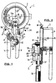
- FIGS. 1 and 2 show a separating device 1 with a rotation guide 2 shown a diametrically divided clamping device 3 with two half-shells 4 and 5, which with each other via a pivot pin 6 are connected.
- the pipe surface is clamped using two Handles 7 and 8, of which one handle 7 via a pivot pin 9 with the half shell 4 and the other handle 8 rigid with the Half shell 5 is connected.
- the clamping takes place by means of an adjustable Toggle lever 10 and two pivot pins 11 and 12.
- the toggle lever 10 is divided, and the clamping force can be determined by means of a threaded sleeve 13 be set, the two internal threads with opposite pitches has.
- To the toggle lever 10 with respect to the threaded pin 9 in the To hold the pressed position is on one of the handles Spacer 14 attached.
- the device is in US 4,845,850 described.
- One of the two half-shells 4 and 5 is rigid with an undivided one Guide ring 15 connected, on which a rotary ring 16 is guided.
- the Rotating ring 16 is in turn rigidly connected to a radial guide 17, in which a tool carrier 18 is slidably guided like a slide.
- Figure 2 the displacement of the tool carrier 18 in both directions by means of a threaded spindle 19 and a turning handle 20, the threaded spindle 19 in a cantilever 21 of the rotary ring 16 is stored.
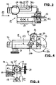
- the invention is based on the tool carrier 18 in FIGS. 3 to 7 explained in more detail, the reference numerals also partially in FIGS. 1 and 2 were transferred:
- the tool carrier 18 is a cutting roller at its radially inner end 22 with a sharp cutting edge 22a by means of a bearing pin 23 exchangeably stored.
- the main plane of the cutting roller 22 extends perpendicular to axis A-A, or their own axis A2 runs parallel to Axis A-A.
- the tool carrier 18 has a T-shaped cross section Guide part 24, in which the threaded spindle 19 engages (Figure 5). about
- the guide part 24 is a further radial guide 25 parallel to this arranged in the relatively displaceable and rotatable a guide pin 26 is stored. In this there is an adjusting screw 27 in a radial orientation stored, the shaft 28 is guided in an angular backdrop 29.
- a Chamfering tool 30 arranged with a cutting edge 31.
- the chamfering tool 30 is at right angles to the axis A3 of the guide pin 26 and the cutting edge at an angle ⁇ of 60 degrees to this.
- the chamfering tool 30 In the retracted position of the guide pin according to FIGS. 3 and 4 there is the chamfering tool 30 to protect the operator in a protective housing 32, the side by means of a screw 33 on Tool carrier 18 attached and towards the pipe to be chamfered is provided with an opening 34 for extending the chamfering tool 30.
- the set screw 27 is at the same time handle and guide means and - by tightening against the radial guide 25 - also locking means for the Guide pin 26.
- the tool holder 18 with a nominal diameter of the tube 35 and the chamfer-related scale 37 provided ( Figure 3), with a reference point, not shown, on the Radial guide 17 is to be congruent.
- the chamfering tool can be pivoted through 90 degrees because its cutting edge 31 the cutting edge 22a of the cutting roller 22 engages as shown in FIGS Figures 6 and 7 is shown.
- the tube 35 is a composite tube with a metal core 38 (for example made of aluminum or copper), an inner coating 39 and an outer coating 40, each made of a plastic.
- a metal core 38 for example made of aluminum or copper
- an inner coating 39 and an outer coating 40 each made of a plastic.
- the operation of the separation device is as follows: First, the separation device 1 with the tensioning device 3 by a predetermined amount Tube 35 pushed on and the clamping device 3 by means of the handles 7 and 8 closed. Then the cutting roller 22 by means of the radial guide 17 and the threaded spindle 19 in the position according to the figures 3 and 4 brought to bear on the outer surface of the tube 35. After that the rotary ring 2 is rotated about the axis A-A by means of the rotary handle 20, with the twist grip 20 continuously adjusted and the cutting edge 22a Cutting roller 22 gradually until the excess pipe length is cut off is moved through all layers of the tube 35. This stops the tightened set screw 27, the chamfering tool 30 in the retracted Position. The tool carrier 18 will end this path stopped.
- the guide pin 26 is relative to stationary tool carrier 18 as far as the inner cross section of the Tube 35 advanced that the chamfering edge 31 of the chamfering tool 30 lies above the free inner cross section of the tube 35. Only then will the chamfering tool 30 by means of the guide pin 26 and the link 29 pivoted 90 degrees into the inner cross section of the tube 35 and locked by the set screw 27. Then the chamfering tool 30 together according to the scale 37 by the threaded spindle 19 withdrawn by the tool carrier 18 by a predetermined amount, until the internal chamfer 36 is completed. After this Open the cutting device 3, the cutting tool 1 is chamfered Tube end removed and the chamfering tool 30 in its protective housing 32 returned.
Landscapes
- Engineering & Computer Science (AREA)
- Mechanical Engineering (AREA)
- Turning (AREA)
- Accessories And Tools For Shearing Machines (AREA)
- Milling, Broaching, Filing, Reaming, And Others (AREA)
Description
- die zusätzliche Radialführung einen drehbaren Führungszapfen besitzt, an dem das Anfaswerkzeug radial abstehend befestigt ist und der eine Stellschraube für die Führung und Arretierung des Führungszapfens gegenüber der Radialführung aufweist, und wenn die Radialführung eine Kulisse für die Führung der Stellschraube in radialer Richtung und in Umfangsrichtung aufweist,
- die Kulisse zwei Schenkel aufweist, von denen der erste Schenkel parallel zur Verschieberichtung des Führungzapfens und der zweite Schenkel rechtwinklig und bogenförmig gekrümmt zum ersten Schenkel verläuft und an einer Stelle angeordnet ist, an der das Anfaswerkzeug in den offenen lichten Rohrquerschnitt einschwenkbar ist,
- das Trennwerkzeug als Schneidrolle mit einer Schneidkante ausgebildet ist und wenn das Anfaswerkzeug in ausgeschwenkter Stellung über die Schneidrolle vorschiebbar und zurückziehbar ist und in radial einwärts vorgeschobener und in den offenen Rohrquerschnitt eingeschwenkter Stellung die Schneidkante übergreift,
- am Werkzeugträger ein Schutzgehäuse befestigt ist, in das das Anfaswerkzeug zurückziehbar ist,
- der Werkzeugträger einen Führungsteil besitzt, mit dem der Werkzeugträger in der hierzu komplementären Radialführung geführt ist,
- der Führungsteil T-förmig ausgebildet ist,
- die Rückzugsbewegung des gegenüber dem Werkzeugträger arretierten Anfaswerkzeugs beim Anfasen mittels der Gewindespindel für den Antrieb des Werkzeugträgers herbeiführbar ist und/oder, wenn
- zwischen dem Werkzeugträger und seiner Radialführung eine Skalierung und ein Bezugspunkt angeordnet sind, durch die eine Vorgabe der Rohrdurchmesser und der Breite der Anfasung herbeiführbar ist.
- Figur 1
- eine Draufsicht auf das Trenngerät in Richtung der Geräteachse A-A, die mit der Rohrachse zusammenfällt,
- Figur 2
- einen teilweisen Axialschnitt durch das Trenngerät entlang der Ebene E-E in Figur 1,
- Figur 3
- eine teilweise geschnittene Seitenansicht des Werkzeugträgers mit Trennwerkzeug und eingezogenem Anfaswerkzeug in Richtung des Pfeils P1 in Figur 1,
- Figur 4
- eine Draufsicht auf den Werkzeugträger nach Figur 3,
- Figur 5
- eine teilweise geschnittene rückseitige Ansicht des Werkzeugträgers nach den Figuren 3 und 4 in Richtung des Pfeils P2 in Figur 3,
- Figur 6
- eine perspektivische Darstellung des Werkzeugträgers nach den Figuren 3 bis 5, jedoch mit ausgefahrenem Anfaswerkzeug, und
- Figur 7
- eine vergrößerte Seitenansicht des Werkzeugträgers nach Figur 6 und einen Ausschnitt aus einem Rohr nach der Anfasung.
- 1
- Trenngerät
- 2
- Rotationsführung
- 3
- Spannvorrichtung
- 4
- Halbschale
- 5
- Halbschale
- 6
- Gelenkzapfen
- 7
- Handgriff
- 8
- Handgriff
- 9
- Gelenkzapfen
- 10
- Kniehebel
- 11
- Gelenkzapfen
- 12
- Gelenkzapfen
- 13
- Gewindehülse
- 14
- Distanzbolzen
- 15
- Führungsring
- 16
- Drehring
- 17
- Radialführung
- 18
- Werkzeugträger
- 19
- Gewindespindel
- 20
- Drehgriff
- 21
- Ausleger
- 22
- Schneid rolle
- 22a
- Schneidkante
- 23
- Lagerzapfen
- 24
- Führungsteil
- 25
- Radialführung
- 26
- Führungszapfen
- 27
- Stellschraube
- 28
- Schaft
- 29
- Kulisse
- 29a
- Schenkel
- 29b
- Schenkel
- 30
- Anfaswerkzeug
- 31
- Anfasschneide
- 32
- Schutzgehäuse
- 33
- Schraube
- 34
- öffnung
- 35
- Rohr
- 36
- Anfasung
- 37
- Skalierung
- 38
- Metallkern
- 39
- Innenbeschichtung
- 40
- Außenbeschichtung
- α
- Winkel
- A-A
- Achse
- A2
- Achse
- A3
- Achse
- E-E
- Ebene
- P1
- Pfeil
- P2
- Pfeil
- P3
- Pfeil
Claims (9)
- Trenngerät für Rohre (35) mit einer Rotationsführung (2) zum Führen des Trenngeräts (1) um die Rohroberfläche und um eine Achse (A-A), mit einer an der Rotationsführung (2) angeordneten Radialführung (17) für einen Werkzeugträger (18), der mit einem Trennwerkzeug (22) und einem Anfaswerkzeug (30) versehen und mittels einer Gewindespindel (19) in Richtung auf die Achse (A-A) und in Gegenrichtung verstellbar ist, dadurch gekennzeichnet, daß der Werkzeugträger (18) eine zusätzliche Radialführung (25) für das Anfaswerkzeug (30) besitzt, mit der das Anfaswerkzeug (30) relativ zum Werkzeugträger (18) von einer Stellung außerhalb der Rohroberfläche in eine Stellung innerhalb des Rohres (35) und in Gegenrichtung zum Herstellen einer inneren Anfasung (36) verstellbar ist.
- Trenngerät nach Anspruch 1, dadurch gekennzeichnet, daß die zusätzliche Radialführung (25) einen drehbaren Führungszapfen (26) besitzt, an dem das Anfaswerkzeug (30) radial abstehend befestigt ist und der eine Stellschraube (27) für die Führung und Arretierung des Führungszapfens (26) gegenüber der Radialführung (25) aufweist, und daß die Radialführung (25) eine Kulisse (29) für die Führung der Stellschraube (27) in radialer Richtung und in Umfangsrichtung aufweist.
- Trenngerät nach Anspruch 2, dadurch gekennzeichnet, daß die Kulisse (29) zwei Schenkel (29a, 29b) aufweist, von denen der erste Schenkel (29a) parallel zur Verschieberichtung des Führungzapfens (26) und der zweite Schenkel (29b) rechtwinklig und bogenförmig gekrümmt zum ersten Schenkel (29a) verläuft und an einer Stelle angeordnet ist, an der das Anfaswerkzeug (30) in den offenen lichten Rohrquerschnitt einschwenkbar ist.
- Trenngerät nach Anspruch 1, dadurch gekennzeichnet, daß das Trennwerkzeug als Schneidrolle (22) mit einer Schneidkante (22a) ausgebildet ist und daß das Anfaswerkzeug (30) in ausgeschwenkter Stellung über die Schneidrolle (22) vorschiebbar und zurückziehbar ist und in radial einwärts vorgeschobener und in den offenen Rohrquerschnitt eingeschwenkter Stellung die Schneidkante (22a) übergreift.
- Trenngerät nach Anspruch 1, dadurch gekennzeichnet, daß am Werkzeugträger (18) ein Schutzgehäuse (32) befestigt ist, in das das Anfaswerkzeug (30) zurückziehbar ist.
- Trenngerät nach Anspruch 1, dadurch gekennzeichnet, daß der Werkzeugträger (18) einen Führungsteil (24) besitzt, mit dem der Werkzeugträger in der hierzu komplementären Radialführung (17) geführt ist.
- Trenngerät nach Anspruch 6, dadurch gekennzeichnet, daß der Führungsteil (24) T-förmig ausgebildet ist.
- Trenngerät nach Anspruch 1, dadurch gekennzeichnet, daß die Rückzugsbewegung des gegenüber dem Werkzeugträger (18) arretierten Anfaswerkzeugs (30) beim Anfasen mittels der Gewindespindel (19) für den Antrieb des Werkzeugträgers (18) herbeiführbar ist.
- Trenngerät nach Anspruch 1, dadurch gekennzeichnet, daß zwischen dem Werkzeugträger (18) und seiner Radialführung (17) eine Skalierung (37) und ein Bezugspunkt angeordnet sind, durch die eine Vorgabe der Rohrdurchmesser und der Breite der Anfasung (36) herbeiführbar ist.
Applications Claiming Priority (2)
| Application Number | Priority Date | Filing Date | Title |
|---|---|---|---|
| DE20103481U DE20103481U1 (de) | 2001-02-28 | 2001-02-28 | Trenngerät für Rohre |
| DE20103481U | 2001-02-28 |
Publications (3)
| Publication Number | Publication Date |
|---|---|
| EP1236529A2 EP1236529A2 (de) | 2002-09-04 |
| EP1236529A3 EP1236529A3 (de) | 2003-05-28 |
| EP1236529B1 true EP1236529B1 (de) | 2004-10-13 |
Family
ID=7953621
Family Applications (1)
| Application Number | Title | Priority Date | Filing Date |
|---|---|---|---|
| EP02000188A Expired - Lifetime EP1236529B1 (de) | 2001-02-28 | 2002-01-10 | Trenngerät für Rohre |
Country Status (4)
| Country | Link |
|---|---|
| EP (1) | EP1236529B1 (de) |
| AT (1) | ATE279289T1 (de) |
| DE (2) | DE20103481U1 (de) |
| ES (1) | ES2230398T3 (de) |
Families Citing this family (3)
| Publication number | Priority date | Publication date | Assignee | Title |
|---|---|---|---|---|
| AR076937A3 (es) | 2010-06-01 | 2011-07-20 | Macroplast S A | Una herramienta manual cortadora/refiladora de tubos flexibles de bajo espesor |
| DE102017112431A1 (de) * | 2017-06-06 | 2018-12-06 | Rothenberger Ag | Trennvorrichtung zum spanlosen Ablängen von Kunststoffwerkstücken, insbesondere Kunststoffrohren |
| US10486248B2 (en) | 2017-06-08 | 2019-11-26 | Greenlee Tools, Inc. | Cutting tool |
Family Cites Families (10)
| Publication number | Priority date | Publication date | Assignee | Title |
|---|---|---|---|---|
| US4063355A (en) | 1976-08-30 | 1977-12-20 | I-T-E Imperial Corporation | Cutter for helically corrugated tube for flexible gas insulated cable |
| DE7811885U1 (de) | 1978-04-20 | 1978-09-07 | Rothenberger Gmbh & Co Werkzeuge- Maschinen Kg, 6000 Frankfurt | Rohrabschneider mit einem nachstellbaren abstechwerkzeug |
| DE7811884U1 (de) | 1978-04-20 | 1978-09-07 | Rothenberger Gmbh & Co Werkzeuge- Maschinen Kg, 6000 Frankfurt | Rohrabschneider mit einer ueber einen handgriff und einen spindeltrieb nachstellbaren schneideinrichtung |
| JPS6225304Y2 (de) * | 1978-10-18 | 1987-06-29 | ||
| DE7904781U1 (de) | 1979-02-21 | 1979-07-26 | Rothenberger Gmbh & Co Werkzeuge- Maschinen Kg, 6000 Frankfurt | Rohrabschneider mit einer kniehebel- spanneinrichtung |
| JPS56500879A (de) | 1979-07-18 | 1981-07-02 | ||
| DD154031A1 (de) | 1980-11-03 | 1982-02-17 | Walter Stein | Vorschubgetriebe zur erzeugung einer radialbewegung an rotierenden werkzeugtraegern |
| DE3136406A1 (de) | 1981-09-14 | 1983-03-24 | Rothenberger GmbH & Co Werkzeuge-Maschinen KG, 6000 Frankfurt | "rohrabschneider, insbesondere fuer kunststoffrohre" |
| DE4409160C1 (de) * | 1994-03-17 | 1995-09-28 | Rothenberger Werkzeuge Masch | Rohrabstechgerät für Kunststoffrohre |
| DE19603361C2 (de) | 1996-01-31 | 2000-10-12 | Fischer G Rohrverbindungstech | Rohrtrenn- und Rohranfasvorrichtung für ein dünnwandiges Rohr |
-
2001
- 2001-02-28 DE DE20103481U patent/DE20103481U1/de not_active Expired - Lifetime
-
2002
- 2002-01-10 EP EP02000188A patent/EP1236529B1/de not_active Expired - Lifetime
- 2002-01-10 DE DE2002501252 patent/DE50201252D1/de not_active Expired - Lifetime
- 2002-01-10 AT AT02000188T patent/ATE279289T1/de not_active IP Right Cessation
- 2002-01-10 ES ES02000188T patent/ES2230398T3/es not_active Expired - Lifetime
Also Published As
| Publication number | Publication date |
|---|---|
| EP1236529A3 (de) | 2003-05-28 |
| DE50201252D1 (de) | 2004-11-18 |
| ES2230398T3 (es) | 2005-05-01 |
| ATE279289T1 (de) | 2004-10-15 |
| DE20103481U1 (de) | 2001-05-17 |
| EP1236529A2 (de) | 2002-09-04 |
Similar Documents
| Publication | Publication Date | Title |
|---|---|---|
| DE69624656T2 (de) | Bohrwerkzeugvorrichtung mit Zentrierbohrer und Hohlbohrkrone | |
| DE69714781T2 (de) | Hydromechanisches futter | |
| DE2062757B2 (de) | Auf einen Spiralbohrer aufschieb bares Entgratwerkzeug | |
| DE2541414A1 (de) | Werkzeug zum anfasen von einem ende eines rohres | |
| DE69422917T2 (de) | Vorrichtung zum apsperren des fluidflusses in einer rohrleitung | |
| DE2744410A1 (de) | 4-backen-spannfutter fuer ein werkstueck | |
| DE3136406C2 (de) | ||
| DE102007045331A1 (de) | Rohrende-Bearbeitungsvorrichtung und damit ausgerüstetes Rohrende-Bearbeitungsgerät | |
| EP0922518B1 (de) | Anfaswerkzeug für rohrförmige Werkstücke | |
| DE7811884U1 (de) | Rohrabschneider mit einer ueber einen handgriff und einen spindeltrieb nachstellbaren schneideinrichtung | |
| DE19800029A1 (de) | Anfaswerkzeug für rohrförmige Werkstücke | |
| EP0229309A1 (de) | Vorrichtung zum Innenspannen von weichem Dreibackenfutter bei Drehmaschinen | |
| EP1236529A2 (de) | Trenngerät für Rohre | |
| DE2946307C2 (de) | Tragbares Gerät zum Gewindeschneiden o.dgl. | |
| DE10233856A1 (de) | Vorrichtung zum Trennen von Rohren | |
| CH670789A5 (de) | ||
| DE3110348C2 (de) | Spannfutter für ein Drehwerkzeug | |
| EP1060809B1 (de) | Aufweitwerkzeug für Rohre | |
| DE3246994A1 (de) | Verfahren und vorrichtung zum automatischen verstellen eines drehwerkzeuges mit schneidentraeger | |
| DE2622566C3 (de) | Rohrabschneider zum Ablängen und gleichzeitigen Anschrägen von Rohren, insbesondere Kunststoffrohren | |
| EP1149666B1 (de) | Zangenartiges Kombinationswerkzeug | |
| DE1627381B2 (de) | Tragbare vorrichtung zum gewindeschneiden an rohren o.dgl. | |
| DE202006007258U1 (de) | Werkzeug zum Bearbeiten eines Rohrendes | |
| DE10324670B4 (de) | Spannfutter | |
| DE102006008818B4 (de) | Vorrichtung zum Schnellspannen eines Werkzeughalters in einer Aufnahme eines Revolvers einer spanabhebenden Werkzeugmaschine |
Legal Events
| Date | Code | Title | Description |
|---|---|---|---|
| PUAI | Public reference made under article 153(3) epc to a published international application that has entered the european phase |
Free format text: ORIGINAL CODE: 0009012 |
|
| AK | Designated contracting states |
Kind code of ref document: A2 Designated state(s): AT BE CH CY DE DK ES FI FR GB GR IE IT LI LU MC NL PT SE TR |
|
| AX | Request for extension of the european patent |
Free format text: AL;LT;LV;MK;RO;SI |
|
| PUAL | Search report despatched |
Free format text: ORIGINAL CODE: 0009013 |
|
| AK | Designated contracting states |
Designated state(s): AT BE CH CY DE DK ES FI FR GB GR IE IT LI LU MC NL PT SE TR |
|
| AX | Request for extension of the european patent |
Extension state: AL LT LV MK RO SI |
|
| 17P | Request for examination filed |
Effective date: 20031108 |
|
| RAP1 | Party data changed (applicant data changed or rights of an application transferred) |
Owner name: ROTHENBERGER AG |
|
| AKX | Designation fees paid |
Designated state(s): AT BE CH CY DE DK ES FI FR GB GR IE IT LI LU MC NL PT SE TR |
|
| GRAP | Despatch of communication of intention to grant a patent |
Free format text: ORIGINAL CODE: EPIDOSNIGR1 |
|
| GRAS | Grant fee paid |
Free format text: ORIGINAL CODE: EPIDOSNIGR3 |
|
| GRAA | (expected) grant |
Free format text: ORIGINAL CODE: 0009210 |
|
| AK | Designated contracting states |
Kind code of ref document: B1 Designated state(s): AT BE CH CY DE DK ES FI FR GB GR IE IT LI LU MC NL PT SE TR |
|
| PG25 | Lapsed in a contracting state [announced via postgrant information from national office to epo] |
Ref country code: NL Free format text: LAPSE BECAUSE OF FAILURE TO SUBMIT A TRANSLATION OF THE DESCRIPTION OR TO PAY THE FEE WITHIN THE PRESCRIBED TIME-LIMIT Effective date: 20041013 Ref country code: IE Free format text: LAPSE BECAUSE OF FAILURE TO SUBMIT A TRANSLATION OF THE DESCRIPTION OR TO PAY THE FEE WITHIN THE PRESCRIBED TIME-LIMIT Effective date: 20041013 Ref country code: FI Free format text: LAPSE BECAUSE OF FAILURE TO SUBMIT A TRANSLATION OF THE DESCRIPTION OR TO PAY THE FEE WITHIN THE PRESCRIBED TIME-LIMIT Effective date: 20041013 Ref country code: TR Free format text: LAPSE BECAUSE OF FAILURE TO SUBMIT A TRANSLATION OF THE DESCRIPTION OR TO PAY THE FEE WITHIN THE PRESCRIBED TIME-LIMIT Effective date: 20041013 Ref country code: FR Free format text: LAPSE BECAUSE OF FAILURE TO SUBMIT A TRANSLATION OF THE DESCRIPTION OR TO PAY THE FEE WITHIN THE PRESCRIBED TIME-LIMIT Effective date: 20041013 |
|
| REG | Reference to a national code |
Ref country code: GB Ref legal event code: FG4D Free format text: NOT ENGLISH |
|
| REG | Reference to a national code |
Ref country code: CH Ref legal event code: EP |
|
| REG | Reference to a national code |
Ref country code: IE Ref legal event code: FG4D Free format text: GERMAN |
|
| REF | Corresponds to: |
Ref document number: 50201252 Country of ref document: DE Date of ref document: 20041118 Kind code of ref document: P |
|
| PG25 | Lapsed in a contracting state [announced via postgrant information from national office to epo] |
Ref country code: LU Free format text: LAPSE BECAUSE OF NON-PAYMENT OF DUE FEES Effective date: 20050110 Ref country code: IT Free format text: LAPSE BECAUSE OF NON-PAYMENT OF DUE FEES Effective date: 20050110 Ref country code: CY Free format text: LAPSE BECAUSE OF FAILURE TO SUBMIT A TRANSLATION OF THE DESCRIPTION OR TO PAY THE FEE WITHIN THE PRESCRIBED TIME-LIMIT Effective date: 20050110 |
|
| PG25 | Lapsed in a contracting state [announced via postgrant information from national office to epo] |
Ref country code: GR Free format text: LAPSE BECAUSE OF FAILURE TO SUBMIT A TRANSLATION OF THE DESCRIPTION OR TO PAY THE FEE WITHIN THE PRESCRIBED TIME-LIMIT Effective date: 20050113 Ref country code: DK Free format text: LAPSE BECAUSE OF FAILURE TO SUBMIT A TRANSLATION OF THE DESCRIPTION OR TO PAY THE FEE WITHIN THE PRESCRIBED TIME-LIMIT Effective date: 20050113 Ref country code: SE Free format text: LAPSE BECAUSE OF FAILURE TO SUBMIT A TRANSLATION OF THE DESCRIPTION OR TO PAY THE FEE WITHIN THE PRESCRIBED TIME-LIMIT Effective date: 20050113 |
|
| PG25 | Lapsed in a contracting state [announced via postgrant information from national office to epo] |
Ref country code: BE Free format text: LAPSE BECAUSE OF NON-PAYMENT OF DUE FEES Effective date: 20050131 Ref country code: MC Free format text: LAPSE BECAUSE OF NON-PAYMENT OF DUE FEES Effective date: 20050131 Ref country code: AT Free format text: LAPSE BECAUSE OF NON-PAYMENT OF DUE FEES Effective date: 20050131 |
|
| GBT | Gb: translation of ep patent filed (gb section 77(6)(a)/1977) |
Effective date: 20050204 |
|
| NLV1 | Nl: lapsed or annulled due to failure to fulfill the requirements of art. 29p and 29m of the patents act | ||
| REG | Reference to a national code |
Ref country code: ES Ref legal event code: FG2A Ref document number: 2230398 Country of ref document: ES Kind code of ref document: T3 |
|
| REG | Reference to a national code |
Ref country code: IE Ref legal event code: FD4D |
|
| BERE | Be: lapsed |
Owner name: ROTHENBERGER A.G. Effective date: 20050131 |
|
| PLBE | No opposition filed within time limit |
Free format text: ORIGINAL CODE: 0009261 |
|
| STAA | Information on the status of an ep patent application or granted ep patent |
Free format text: STATUS: NO OPPOSITION FILED WITHIN TIME LIMIT |
|
| 26N | No opposition filed |
Effective date: 20050714 |
|
| EN | Fr: translation not filed | ||
| PG25 | Lapsed in a contracting state [announced via postgrant information from national office to epo] |
Ref country code: LI Free format text: LAPSE BECAUSE OF NON-PAYMENT OF DUE FEES Effective date: 20060131 Ref country code: CH Free format text: LAPSE BECAUSE OF NON-PAYMENT OF DUE FEES Effective date: 20060131 |
|
| REG | Reference to a national code |
Ref country code: CH Ref legal event code: PL |
|
| BERE | Be: lapsed |
Owner name: *ROTHENBERGER A.G. Effective date: 20050131 |
|
| PG25 | Lapsed in a contracting state [announced via postgrant information from national office to epo] |
Ref country code: PT Free format text: LAPSE BECAUSE OF NON-PAYMENT OF DUE FEES Effective date: 20050313 |
|
| PGRI | Patent reinstated in contracting state [announced from national office to epo] |
Ref country code: IT Effective date: 20091201 |
|
| REG | Reference to a national code |
Ref country code: DE Ref legal event code: R082 Ref document number: 50201252 Country of ref document: DE Representative=s name: LAUNHARDT, THOMAS, DIPL.-ING. DR.-ING., DE |
|
| PGFP | Annual fee paid to national office [announced via postgrant information from national office to epo] |
Ref country code: IT Payment date: 20120125 Year of fee payment: 11 |
|
| PGFP | Annual fee paid to national office [announced via postgrant information from national office to epo] |
Ref country code: DE Payment date: 20130122 Year of fee payment: 12 Ref country code: ES Payment date: 20130128 Year of fee payment: 12 Ref country code: GB Payment date: 20130122 Year of fee payment: 12 |
|
| REG | Reference to a national code |
Ref country code: DE Ref legal event code: R119 Ref document number: 50201252 Country of ref document: DE |
|
| GBPC | Gb: european patent ceased through non-payment of renewal fee |
Effective date: 20140110 |
|
| PG25 | Lapsed in a contracting state [announced via postgrant information from national office to epo] |
Ref country code: DE Free format text: LAPSE BECAUSE OF NON-PAYMENT OF DUE FEES Effective date: 20140801 |
|
| REG | Reference to a national code |
Ref country code: DE Ref legal event code: R119 Ref document number: 50201252 Country of ref document: DE Effective date: 20140801 |
|
| PG25 | Lapsed in a contracting state [announced via postgrant information from national office to epo] |
Ref country code: GB Free format text: LAPSE BECAUSE OF NON-PAYMENT OF DUE FEES Effective date: 20140110 |
|
| REG | Reference to a national code |
Ref country code: ES Ref legal event code: FD2A Effective date: 20150327 |
|
| PG25 | Lapsed in a contracting state [announced via postgrant information from national office to epo] |
Ref country code: ES Free format text: LAPSE BECAUSE OF NON-PAYMENT OF DUE FEES Effective date: 20140111 |
|
| PG25 | Lapsed in a contracting state [announced via postgrant information from national office to epo] |
Ref country code: IT Free format text: LAPSE BECAUSE OF NON-PAYMENT OF DUE FEES Effective date: 20140110 |