EP1236523A1 - Ausziehvorrichtung, insbesondere Puller - Google Patents
Ausziehvorrichtung, insbesondere Puller Download PDFInfo
- Publication number
- EP1236523A1 EP1236523A1 EP02004098A EP02004098A EP1236523A1 EP 1236523 A1 EP1236523 A1 EP 1236523A1 EP 02004098 A EP02004098 A EP 02004098A EP 02004098 A EP02004098 A EP 02004098A EP 1236523 A1 EP1236523 A1 EP 1236523A1
- Authority
- EP
- European Patent Office
- Prior art keywords
- counter
- holder
- clamping
- pull
- transport
- Prior art date
- Legal status (The legal status is an assumption and is not a legal conclusion. Google has not performed a legal analysis and makes no representation as to the accuracy of the status listed.)
- Granted
Links
Images


Classifications
-
- B—PERFORMING OPERATIONS; TRANSPORTING
- B21—MECHANICAL METAL-WORKING WITHOUT ESSENTIALLY REMOVING MATERIAL; PUNCHING METAL
- B21C—MANUFACTURE OF METAL SHEETS, WIRE, RODS, TUBES, PROFILES OR LIKE SEMI-MANUFACTURED PRODUCTS OTHERWISE THAN BY ROLLING; AUXILIARY OPERATIONS USED IN CONNECTION WITH METAL-WORKING WITHOUT ESSENTIALLY REMOVING MATERIAL
- B21C35/00—Removing work or waste from extruding presses; Drawing-off extruded work; Cleaning dies, ducts, containers, or mandrels for metal extruding
- B21C35/02—Removing or drawing-off work
- B21C35/03—Straightening the work
-
- B—PERFORMING OPERATIONS; TRANSPORTING
- B29—WORKING OF PLASTICS; WORKING OF SUBSTANCES IN A PLASTIC STATE IN GENERAL
- B29C—SHAPING OR JOINING OF PLASTICS; SHAPING OF MATERIAL IN A PLASTIC STATE, NOT OTHERWISE PROVIDED FOR; AFTER-TREATMENT OF THE SHAPED PRODUCTS, e.g. REPAIRING
- B29C48/00—Extrusion moulding, i.e. expressing the moulding material through a die or nozzle which imparts the desired form; Apparatus therefor
- B29C48/25—Component parts, details or accessories; Auxiliary operations
- B29C48/355—Conveyors for extruded articles
-
- B—PERFORMING OPERATIONS; TRANSPORTING
- B29—WORKING OF PLASTICS; WORKING OF SUBSTANCES IN A PLASTIC STATE IN GENERAL
- B29C—SHAPING OR JOINING OF PLASTICS; SHAPING OF MATERIAL IN A PLASTIC STATE, NOT OTHERWISE PROVIDED FOR; AFTER-TREATMENT OF THE SHAPED PRODUCTS, e.g. REPAIRING
- B29C48/00—Extrusion moulding, i.e. expressing the moulding material through a die or nozzle which imparts the desired form; Apparatus therefor
- B29C48/03—Extrusion moulding, i.e. expressing the moulding material through a die or nozzle which imparts the desired form; Apparatus therefor characterised by the shape of the extruded material at extrusion
- B29C48/09—Articles with cross-sections having partially or fully enclosed cavities, e.g. pipes or channels
Definitions
- the present invention relates to a pull-out device, especially pullers for clamping extruded profiles from extrusion plants, with at least one Clamping device from a clamping element and a Backstop.
- Such pull-out devices are in a variety of forms and execution known and available in the market. You serve essentially for pulling out and stretching one out of a Press extruded profile to this example. place on a transport device and at the same time to stretch. While pulling out or stretching the extruded profiles are common cooled down, because of the deformation during extrusion Extruded profile is heated to a high temperature Temperature from about 500 ° to 520 ° C.
- the present invention has for its object a To create pull-out device of the type mentioned at the outset, which eliminates the disadvantages mentioned, with which one effective gripping of extruded profiles is possible, and a very quick release and process at minimal space requirement of the pull-out device is feasible. Furthermore, such Pull-out device during an overtaking process, in particular at an overtaking point of two pull-out devices, especially clamping devices extremely little space take in. Such pull-out devices should be quick Movable along guidance systems, accelerable in X and Z direction can be moved independently.
- the clamping element against the counter-holder is movable.
- the tensioning element is preferably in Recesses stored in the corresponding side parts.
- the counter holder can be positioned within one level move that runs parallel to a transport plane.
- the Counterholder can preferably be at least one Drive element from the recesses in the side parts commonlyverschwenken. He can preferably be moved around Swivel 90 ° so that it is approximately parallel to the Longitudinal direction of the transport device is arranged, and between the side parts and the clamping element also one Opening is formed. This allows the Clamping device which has no extruded profile picks up, move over the other jig to immediately after taking off the first Extruded profiles the next pressed again Extruding extruded profiles directly on the press.
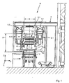
- FIG. 1 one according to the invention Pull-out device R on a transport device 1, which with a variety of passively moving or is actively driven roller elements 2, which like not shown here, are designed to be lowerable.
- the transport device 1 immediately closes here extrusion system, not shown. This spills over a frame 4, the transport device 1, on which in preferred embodiment via guidance systems 5.1, 5.2, two pullers 6.1, 6.2 linearly along an X direction are movable back and forth.
- the Puller 6.1, 6.2 are provided with clamping devices 7.1, 7.2 which are arranged above the transport device 1.
- the Clamping device 7.1, 7.2 is used for receiving and Clamping a directly emerging from a press or extruded profile 8, see FIG. 3.
- the puller 6.1 or 6.2 takes one directly from the Extruded profile 8 emerging with its Clamping device 7.1 or 7.2. During the Extrusion process from the press becomes the extruded profile 8 stretched over the transport device 1 or by means the puller 6.1, 6.2 moves.
- Cooling device 9.2 above the transport device 1 arranged.
- the cooling device 9.2 is approximately in the middle and close above the transport device 1 over a width B, which corresponds approximately to the transport device 1, arranged.
- the guidance systems 5.1 and 5.2 are each also on the side of the frame 4 next to the cooling device 9.1 arranged.
- the cooling device 9.1 can A plurality of nozzle elements 10 for dispensing cold Have air or cold gas.
- the Nozzle elements 10 over the full length and full width B of the cooling device 9.1 on one Bottom 11 may be arranged.
- the cooling device 9.1 via air supply devices not shown here supplied with cold air to the squeezed Extruded profiles 8 to cool.
- Cooling device 9.1 is particularly close to one smallest possible distance A to the roller elements 2 Transport device 1 is spaced, and yet a Puller 6.1, 6.2 or clamping devices 7.1, 7.2 also one above the other, as shown in Figure 1 is, is possible, has proven to be particularly advantageous in of the present invention Clamping device 7.1, 7.2, each with a clamping element 12 and a counter support 13.
- the counter-holder 13 of the tensioning device 7.2 is, however, over the full width of the transport device 1 arranged and engages in the respective side parts 15 in here only indicated recesses 16 and will stored or held there.
- the counter holder 13 is in a plane E1 pivoted parallel to one Transport plane E2 of the transport device 1 runs.
- the clamping element 12 is, as indicated in Figure 2, against the counter holder 13 can be pivoted around the extruded profiles 8, as indicated in Figure 3, between the counterhold 13 and clamping element 12 for pulling out of the press clamp.
- the counter-holder 13 about a pivot axis 17th pivoted by 90 °, the counter-holder 13 is approximately parallel to the transport devices, not shown here 1 arranged so that between the Side parts 15 and the tensioning element 12 have an opening 18 is released.
- the transport devices not shown here 1 arranged so that between the Side parts 15 and the tensioning element 12 have an opening 18 is released.
- FIGS. 1 and 2 can be inside the opening 18 at Overtaking process of the clamping device 7.1 and 7.2
- the counter-holder 13 is preferably pivoted in or with a direction of movement of the clamping device 7.1, 7.2 to the press by 90 °.
- the counter-holder 13 is pivoted counter to the pulling direction of the clamping device 7.1, 7.2.
Landscapes
- Engineering & Computer Science (AREA)
- Mechanical Engineering (AREA)
- Extrusion Of Metal (AREA)
- Treatment Of Fiber Materials (AREA)
- Paper (AREA)
- Saccharide Compounds (AREA)
Abstract
Description
| Positionszahlenliste | |||||
| 1 | Transporteinrichtung | 34 | 67 | ||
| 2 | Walzenelemente | 35 | 68 | ||
| 3 | 36 | 69 | |||
| 4 | Gestell | 37 | 70 | ||
| 5 | Führungssystem | 38 | 71 | ||
| 6 | Puller | 39 | 72 | ||
| 7 | Einspanneinrichtung | 40 | 73 | ||
| 8 | Strangpressprofil | 41 | 74 | ||
| 9 | Kühleinrichtung | 42 | 75 | ||
| 10 | Düsenelement | 43 | 76 | ||
| 11 | Unterseite | 44 | 77 | ||
| 12 | Spannelement | 45 | 78 | ||
| 13 | Gegenhalter | 46 | 79 | ||
| 14 | Transportbereich | 47 | R | Ausziehvorrichtung | |
| 15 | Seitenteil | 48 | A | Abstand | |
| 16 | Ausnehmung | 49 | B | Breite | |
| 17 | Schwenkachse | 50 | E1 | Ebene | |
| 18 | Öffnung | 51 | E2 | Transportebene | |
| 19 | Antriebselement | 52 | |||
| 20 | 53 | ||||
| 21 | 54 | X | Bewegungsrichtung | ||
| 22 | 55 | ||||
| 23 | 56 | Z | Richtung | ||
| 24 | 57 | ||||
| 25 | 58 | ||||
| 26 | 59 | ||||
| 27 | 60 | ||||
| 28 | 61 | ||||
| 29 | 62 | ||||
| 30 | 63 | ||||
| 31 | 64 | ||||
| 32 | 65 | ||||
| 33 | 66 |
Claims (13)
- Ausziehvorrichtung, insbesondere Puller zum Einspannen von Strangpressprofilen (8) aus Strangpressanlagen, mit zumindest einer Einspanneinrichtung (7.1, 7.2) aus einem Spannelement (12) und einem Gegenhalter (13),
dadurch gekennzeichnet, dass der Gegenhalter (13) gegenüber dem Spannelement (12) bewegbar, insbesondere verschwenkbar angeordnet ist. - Ausziehvorrichtung, insbesondere Puller zum Einspannen von Strangpressprofilen (8) aus Strangpressanlagen, mit zumindest einer Einspanneinrichtung (7.1, 7.2) aus einem Spannelement (12) und einem Gegenhalter (13), dadurch gekennzeichnet, dass der zumindest eine Gegenhalter (13) aus einem Transportbereich (14) der Strangpressprofile (8) herausschwenkbar ist.
- Ausziehvorrichtung, insbesondere Puller zum Einspannen von Strangpressprofilen (8) aus Strangpressanlagen, mit zumindest einer Einspanneinrichtung (7.1, 7.2) aus einem Spannelement (12) und einem Gegenhalter (13), dadurch gekennzeichnet, dass zum Überholen nahe übereinander verfahrbarer Einspanneinrichtungen (7.1, 7.2) bzw. Puller zumindest ein Gegenhalter (13) des überholenden Pullers herausgeschwenkt ist.
- Ausziehvorrichtung nach wenigstens einem der Ansprüche 1 bis 3, dadurch gekennzeichnet, dass der Gegenhalter (13) in einer Ebene (E1) verschwenkbar angeordnet ist, die in etwa parallel zu einer Transportebene (E2) einer Transporteinrichtung (1) ist.
- Ausziehvorrichtung nach wenigstens einem der Ansprüche 1 bis 4, dadurch gekennzeichnet, dass der Gegenhalter (13) in einer Bewegungsrichtung (X) beim Verfahren der Einspanneinrichtung (7.1, 7.2) gegen die Strangpressanlage verschwenkbar, insbesondere verfahrbar ist.
- Ausziehvorrichtung nach wenigstens einem der Ansprüche 1 bis 5, dadurch gekennzeichnet, dass der Gegenhalter (13) um etwa 90°Grad verschwenkbar angeordnet ist.
- Ausziehvorrichtung nach wenigstens einem der Ansprüche 4 bis 6, dadurch gekennzeichnet, dass nach einem Verschwenken des Gegenhalters (13) dieser in etwa parallel zur Transporteinrichtung (1) angeordnet ist.
- Ausziehvorrichtung nach wenigstens einem der Ansprüche 1 bis 7, dadurch gekennzeichnet, dass durch Verschwenken des Gegenhalters (13) eine Öffnung (18) zwischen Spannelement (12) und Seitenteilen (15) gebildet ist.
- Ausziehvorrichtung nach Anspruch 8, dadurch gekennzeichnet, dass durch die gebildet Öffnung (18) die Einspanneinrichtung (7.1, 7.2), insbesondere der Puller nahe über der Transporteinrichtung (1) verfahrbar ist, wobei die Seitenteile (15), die auf der Transporteinrichtung (1) verbleibenden Strangpressprofile (8) jeweils seitlich übergreifen.
- Ausziehvorrichtung nach wenigstens einem der Ansprüche 1 bis 9, dadurch gekennzeichnet, dass der Gegenhalter (13) über wenigstens ein Antriebselement (19) verschwenkbar angeordnet ist.
- Ausziehvorrichtung nach Anspruch 10, dadurch gekennzeichnet, dass das Antriebselement (19) einem der Seitenteile (15) zugeordnet ist, wobei in dem jeweiligen anderen Seitenteil (15) zumindest eine Ausnehmung (16) zur Halterung und zur Lagerung des Gegenhalters (13) vorgesehen ist.
- Ausziehvorrichtung nach wenigstens einem der Ansprüche 1 bis 11, dadurch gekennzeichnet, dass die Einspanneinrichtung (7.1, 7.2), insbesondere Spannelement (12) und Gegenhalter (13) entlang eines Führungssystemes (5.1, 5.2) in und entgegen der Bewegungsrichtung (X) und die Einspanneinrichtung (7.1, 7.2) in und entgegen einer (Z) Richtung verfahrbar angeordnet sind.
- Ausziehvorrichtung nach wenigstens einem der Ansprüche 4 bis 10, dadurch gekennzeichnet, dass die Transporteinrichtung (1) mit einer Mehrzahl von Walzenelementen (2) versehen ist, die unter die Transportebene (E2) versenkbar, insbesondere verfahrbar sind, wobei der Gegenhalter (13) unter die Transportebene (E2) verfahrbar ist und bei eingefahrenen Walzenelementen (2) unterhalb der Transportebene (E2) verschwenkbar ist.
Applications Claiming Priority (2)
| Application Number | Priority Date | Filing Date | Title |
|---|---|---|---|
| DE10109751A DE10109751A1 (de) | 2001-02-28 | 2001-02-28 | Ausziehvorrichtung, insbesondere Puller |
| DE10109751 | 2001-02-28 |
Publications (2)
| Publication Number | Publication Date |
|---|---|
| EP1236523A1 true EP1236523A1 (de) | 2002-09-04 |
| EP1236523B1 EP1236523B1 (de) | 2007-03-28 |
Family
ID=7675862
Family Applications (1)
| Application Number | Title | Priority Date | Filing Date |
|---|---|---|---|
| EP02004098A Expired - Lifetime EP1236523B1 (de) | 2001-02-28 | 2002-02-25 | Ausziehvorrichtung, insbesondere Puller |
Country Status (4)
| Country | Link |
|---|---|
| EP (1) | EP1236523B1 (de) |
| AT (1) | ATE357981T1 (de) |
| DE (2) | DE10109751A1 (de) |
| ES (1) | ES2287196T3 (de) |
Citations (3)
| Publication number | Priority date | Publication date | Assignee | Title |
|---|---|---|---|---|
| GB2174516A (en) * | 1984-02-10 | 1986-11-05 | Elhaus Friedrich W | System for controlling a puller assembly |
| US4628719A (en) * | 1984-12-27 | 1986-12-16 | R. L. Best Company, Inc. | Puller apparatus |
| EP0646426A1 (de) * | 1993-10-04 | 1995-04-05 | Walter Reisch | Abzugsvorrichtung an Strangpressen |
-
2001
- 2001-02-28 DE DE10109751A patent/DE10109751A1/de not_active Withdrawn
-
2002
- 2002-02-25 ES ES02004098T patent/ES2287196T3/es not_active Expired - Lifetime
- 2002-02-25 AT AT02004098T patent/ATE357981T1/de active
- 2002-02-25 EP EP02004098A patent/EP1236523B1/de not_active Expired - Lifetime
- 2002-02-25 DE DE50209811T patent/DE50209811D1/de not_active Expired - Lifetime
Patent Citations (3)
| Publication number | Priority date | Publication date | Assignee | Title |
|---|---|---|---|---|
| GB2174516A (en) * | 1984-02-10 | 1986-11-05 | Elhaus Friedrich W | System for controlling a puller assembly |
| US4628719A (en) * | 1984-12-27 | 1986-12-16 | R. L. Best Company, Inc. | Puller apparatus |
| EP0646426A1 (de) * | 1993-10-04 | 1995-04-05 | Walter Reisch | Abzugsvorrichtung an Strangpressen |
Also Published As
| Publication number | Publication date |
|---|---|
| DE10109751A1 (de) | 2002-09-05 |
| EP1236523B1 (de) | 2007-03-28 |
| ATE357981T1 (de) | 2007-04-15 |
| DE50209811D1 (de) | 2007-05-10 |
| ES2287196T3 (es) | 2007-12-16 |
Similar Documents
| Publication | Publication Date | Title |
|---|---|---|
| EP0456121B1 (de) | Verfahren zum Biegen von plattenförmigen Werkstücken sowie Biegemaschine zur Durchführung des Verfahrens | |
| DE1679961B1 (de) | Vorrichtung zum Woelben einer sich in plastischen Zustand befindenden Platte mit einer Woelbeform | |
| DE3142378C2 (de) | ||
| DE3119708C2 (de) | ||
| DE19649073A1 (de) | Vorrichtung zur Abkühlung von Strangpreßprofilen | |
| DE69402284T2 (de) | Vorrichtung zum Verarbeiten von Stangen insbesondere Stangen für Stahlbeton | |
| EP2013134B1 (de) | Hubtischm, insbesondere für kleine hubhöhen | |
| EP1236523A1 (de) | Ausziehvorrichtung, insbesondere Puller | |
| EP0878251B1 (de) | Transferpresse mit seitlicher Haltemittelablage an einem bewegbaren Pressentisch | |
| DE4206939C1 (de) | ||
| DE4033977C2 (de) | Spannvorrichtung für Kettfäden | |
| DE1427856A1 (de) | Verfahren und Vorrichtung zur Steuerung der Kuehlgeschwindigkeit und zur Handhabung von heissen langgestreckten Koerpern | |
| DE10124224B4 (de) | Transportvorrichtung für Formkästen in einer Mogulanlage | |
| DE19537995A1 (de) | Vorrichtung zum Überführen schwerer Lasten | |
| DE102016216768B4 (de) | Fertigungsvorrichtung | |
| EP1232809A1 (de) | Strangpressanlage mit wenigstens einer Ausziehvorrichtung | |
| DE102005039466B4 (de) | Regallager mit einem Regalbediengerät | |
| DE1679961C (de) | Vorrichtung zum Wölben einer sich in plastischem Zustand befindenden Platte mit einer Wölbeform | |
| EP3662101A1 (de) | Vorrichtung zum abzug eines bahnförmigen produktes von einer webmaschine | |
| DE3408944A1 (de) | Einrichtung zum haerten von scheibenfoermigen werkstuecken | |
| DE29515719U1 (de) | Biegemaschine | |
| DE2026758C3 (de) | Wendevorrichtung für Stabmaterial an einer horizontalen Richtpresse | |
| DE102005063364B4 (de) | Regallager mit einem Regalbediengerät | |
| DE102022120897A1 (de) | Vorrichtung und Verfahren zum Aufbringen von Befettungsmitteln auf eine Werkstoffoberfläche | |
| DE2053729A1 (de) | Forderer |
Legal Events
| Date | Code | Title | Description |
|---|---|---|---|
| PUAI | Public reference made under article 153(3) epc to a published international application that has entered the european phase |
Free format text: ORIGINAL CODE: 0009012 |
|
| AK | Designated contracting states |
Kind code of ref document: A1 Designated state(s): AT BE CH CY DE DK ES FI FR GB GR IE IT LI LU MC NL PT SE TR |
|
| AX | Request for extension of the european patent |
Free format text: AL;LT;LV;MK;RO;SI |
|
| 17P | Request for examination filed |
Effective date: 20021109 |
|
| AKX | Designation fees paid |
Designated state(s): AT BE CH CY DE DK ES FI FR GB GR IE IT LI LU MC NL PT SE TR |
|
| RAP1 | Party data changed (applicant data changed or rights of an application transferred) |
Owner name: EXPERT KONSTRUKTIONS GMBH |
|
| RIN1 | Information on inventor provided before grant (corrected) |
Inventor name: KELLER, CHRISTOPH |
|
| RAP1 | Party data changed (applicant data changed or rights of an application transferred) |
Owner name: SMS EUMUCO GMBH |
|
| GRAP | Despatch of communication of intention to grant a patent |
Free format text: ORIGINAL CODE: EPIDOSNIGR1 |
|
| GRAS | Grant fee paid |
Free format text: ORIGINAL CODE: EPIDOSNIGR3 |
|
| GRAA | (expected) grant |
Free format text: ORIGINAL CODE: 0009210 |
|
| AK | Designated contracting states |
Kind code of ref document: B1 Designated state(s): AT BE CH CY DE DK ES FI FR GB GR IE IT LI LU MC NL PT SE TR |
|
| PG25 | Lapsed in a contracting state [announced via postgrant information from national office to epo] |
Ref country code: FI Free format text: LAPSE BECAUSE OF FAILURE TO SUBMIT A TRANSLATION OF THE DESCRIPTION OR TO PAY THE FEE WITHIN THE PRESCRIBED TIME-LIMIT Effective date: 20070328 Ref country code: NL Free format text: LAPSE BECAUSE OF FAILURE TO SUBMIT A TRANSLATION OF THE DESCRIPTION OR TO PAY THE FEE WITHIN THE PRESCRIBED TIME-LIMIT Effective date: 20070328 |
|
| REG | Reference to a national code |
Ref country code: GB Ref legal event code: FG4D Free format text: NOT ENGLISH |
|
| REG | Reference to a national code |
Ref country code: CH Ref legal event code: EP |
|
| REF | Corresponds to: |
Ref document number: 50209811 Country of ref document: DE Date of ref document: 20070510 Kind code of ref document: P |
|
| REG | Reference to a national code |
Ref country code: IE Ref legal event code: FG4D Free format text: LANGUAGE OF EP DOCUMENT: GERMAN |
|
| PG25 | Lapsed in a contracting state [announced via postgrant information from national office to epo] |
Ref country code: SE Free format text: LAPSE BECAUSE OF FAILURE TO SUBMIT A TRANSLATION OF THE DESCRIPTION OR TO PAY THE FEE WITHIN THE PRESCRIBED TIME-LIMIT Effective date: 20070628 |
|
| PG25 | Lapsed in a contracting state [announced via postgrant information from national office to epo] |
Ref country code: PT Free format text: LAPSE BECAUSE OF FAILURE TO SUBMIT A TRANSLATION OF THE DESCRIPTION OR TO PAY THE FEE WITHIN THE PRESCRIBED TIME-LIMIT Effective date: 20070828 |
|
| GBT | Gb: translation of ep patent filed (gb section 77(6)(a)/1977) |
Effective date: 20070815 |
|
| ET | Fr: translation filed | ||
| NLV1 | Nl: lapsed or annulled due to failure to fulfill the requirements of art. 29p and 29m of the patents act | ||
| REG | Reference to a national code |
Ref country code: IE Ref legal event code: FD4D |
|
| REG | Reference to a national code |
Ref country code: ES Ref legal event code: FG2A Ref document number: 2287196 Country of ref document: ES Kind code of ref document: T3 |
|
| PG25 | Lapsed in a contracting state [announced via postgrant information from national office to epo] |
Ref country code: DK Free format text: LAPSE BECAUSE OF FAILURE TO SUBMIT A TRANSLATION OF THE DESCRIPTION OR TO PAY THE FEE WITHIN THE PRESCRIBED TIME-LIMIT Effective date: 20070328 Ref country code: IE Free format text: LAPSE BECAUSE OF FAILURE TO SUBMIT A TRANSLATION OF THE DESCRIPTION OR TO PAY THE FEE WITHIN THE PRESCRIBED TIME-LIMIT Effective date: 20070328 |
|
| PLBE | No opposition filed within time limit |
Free format text: ORIGINAL CODE: 0009261 |
|
| STAA | Information on the status of an ep patent application or granted ep patent |
Free format text: STATUS: NO OPPOSITION FILED WITHIN TIME LIMIT |
|
| 26N | No opposition filed |
Effective date: 20080102 |
|
| PG25 | Lapsed in a contracting state [announced via postgrant information from national office to epo] |
Ref country code: GR Free format text: LAPSE BECAUSE OF FAILURE TO SUBMIT A TRANSLATION OF THE DESCRIPTION OR TO PAY THE FEE WITHIN THE PRESCRIBED TIME-LIMIT Effective date: 20070629 |
|
| BERE | Be: lapsed |
Owner name: SMS EUMUCO G.M.B.H. Effective date: 20080228 |
|
| REG | Reference to a national code |
Ref country code: GB Ref legal event code: 732E |
|
| REG | Reference to a national code |
Ref country code: CH Ref legal event code: PL |
|
| PG25 | Lapsed in a contracting state [announced via postgrant information from national office to epo] |
Ref country code: MC Free format text: LAPSE BECAUSE OF NON-PAYMENT OF DUE FEES Effective date: 20080228 Ref country code: LI Free format text: LAPSE BECAUSE OF NON-PAYMENT OF DUE FEES Effective date: 20080229 Ref country code: CH Free format text: LAPSE BECAUSE OF NON-PAYMENT OF DUE FEES Effective date: 20080229 |
|
| PG25 | Lapsed in a contracting state [announced via postgrant information from national office to epo] |
Ref country code: BE Free format text: LAPSE BECAUSE OF NON-PAYMENT OF DUE FEES Effective date: 20080228 |
|
| REG | Reference to a national code |
Ref country code: FR Ref legal event code: TP |
|
| PG25 | Lapsed in a contracting state [announced via postgrant information from national office to epo] |
Ref country code: CY Free format text: LAPSE BECAUSE OF FAILURE TO SUBMIT A TRANSLATION OF THE DESCRIPTION OR TO PAY THE FEE WITHIN THE PRESCRIBED TIME-LIMIT Effective date: 20070328 |
|
| PGFP | Annual fee paid to national office [announced via postgrant information from national office to epo] |
Ref country code: GB Payment date: 20100216 Year of fee payment: 9 |
|
| PG25 | Lapsed in a contracting state [announced via postgrant information from national office to epo] |
Ref country code: LU Free format text: LAPSE BECAUSE OF NON-PAYMENT OF DUE FEES Effective date: 20080225 |
|
| PG25 | Lapsed in a contracting state [announced via postgrant information from national office to epo] |
Ref country code: TR Free format text: LAPSE BECAUSE OF FAILURE TO SUBMIT A TRANSLATION OF THE DESCRIPTION OR TO PAY THE FEE WITHIN THE PRESCRIBED TIME-LIMIT Effective date: 20070328 |
|
| PGFP | Annual fee paid to national office [announced via postgrant information from national office to epo] |
Ref country code: AT Payment date: 20110131 Year of fee payment: 10 Ref country code: IT Payment date: 20110120 Year of fee payment: 10 Ref country code: FR Payment date: 20110215 Year of fee payment: 10 |
|
| PGFP | Annual fee paid to national office [announced via postgrant information from national office to epo] |
Ref country code: DE Payment date: 20110325 Year of fee payment: 10 Ref country code: ES Payment date: 20110202 Year of fee payment: 10 |
|
| GBPC | Gb: european patent ceased through non-payment of renewal fee |
Effective date: 20110225 |
|
| PG25 | Lapsed in a contracting state [announced via postgrant information from national office to epo] |
Ref country code: GB Free format text: LAPSE BECAUSE OF NON-PAYMENT OF DUE FEES Effective date: 20110225 |
|
| REG | Reference to a national code |
Ref country code: FR Ref legal event code: ST Effective date: 20121031 |
|
| PG25 | Lapsed in a contracting state [announced via postgrant information from national office to epo] |
Ref country code: IT Free format text: LAPSE BECAUSE OF NON-PAYMENT OF DUE FEES Effective date: 20120225 |
|
| REG | Reference to a national code |
Ref country code: AT Ref legal event code: MM01 Ref document number: 357981 Country of ref document: AT Kind code of ref document: T Effective date: 20120225 |
|
| REG | Reference to a national code |
Ref country code: DE Ref legal event code: R119 Ref document number: 50209811 Country of ref document: DE Effective date: 20120901 |
|
| PG25 | Lapsed in a contracting state [announced via postgrant information from national office to epo] |
Ref country code: FR Free format text: LAPSE BECAUSE OF NON-PAYMENT OF DUE FEES Effective date: 20120229 Ref country code: AT Free format text: LAPSE BECAUSE OF NON-PAYMENT OF DUE FEES Effective date: 20120225 |
|
| PG25 | Lapsed in a contracting state [announced via postgrant information from national office to epo] |
Ref country code: DE Free format text: LAPSE BECAUSE OF NON-PAYMENT OF DUE FEES Effective date: 20120901 |
|
| REG | Reference to a national code |
Ref country code: ES Ref legal event code: FD2A Effective date: 20130709 |
|
| PG25 | Lapsed in a contracting state [announced via postgrant information from national office to epo] |
Ref country code: ES Free format text: LAPSE BECAUSE OF NON-PAYMENT OF DUE FEES Effective date: 20120226 |