EP1234916A2 - Méthode pour construire des colonnes - Google Patents
Méthode pour construire des colonnes Download PDFInfo
- Publication number
- EP1234916A2 EP1234916A2 EP02003803A EP02003803A EP1234916A2 EP 1234916 A2 EP1234916 A2 EP 1234916A2 EP 02003803 A EP02003803 A EP 02003803A EP 02003803 A EP02003803 A EP 02003803A EP 1234916 A2 EP1234916 A2 EP 1234916A2
- Authority
- EP
- European Patent Office
- Prior art keywords
- column section
- load
- column
- bearing
- supportable
- Prior art date
- Legal status (The legal status is an assumption and is not a legal conclusion. Google has not performed a legal analysis and makes no representation as to the accuracy of the status listed.)
- Granted
Links
Images


Classifications
-
- E—FIXED CONSTRUCTIONS
- E02—HYDRAULIC ENGINEERING; FOUNDATIONS; SOIL SHIFTING
- E02D—FOUNDATIONS; EXCAVATIONS; EMBANKMENTS; UNDERGROUND OR UNDERWATER STRUCTURES
- E02D3/00—Improving or preserving soil or rock, e.g. preserving permafrost soil
- E02D3/12—Consolidating by placing solidifying or pore-filling substances in the soil
- E02D3/123—Consolidating by placing solidifying or pore-filling substances in the soil and compacting the soil
-
- E—FIXED CONSTRUCTIONS
- E02—HYDRAULIC ENGINEERING; FOUNDATIONS; SOIL SHIFTING
- E02D—FOUNDATIONS; EXCAVATIONS; EMBANKMENTS; UNDERGROUND OR UNDERWATER STRUCTURES
- E02D3/00—Improving or preserving soil or rock, e.g. preserving permafrost soil
- E02D3/02—Improving by compacting
- E02D3/08—Improving by compacting by inserting stones or lost bodies, e.g. compaction piles
-
- E—FIXED CONSTRUCTIONS
- E02—HYDRAULIC ENGINEERING; FOUNDATIONS; SOIL SHIFTING
- E02D—FOUNDATIONS; EXCAVATIONS; EMBANKMENTS; UNDERGROUND OR UNDERWATER STRUCTURES
- E02D7/00—Methods or apparatus for placing sheet pile bulkheads, piles, mouldpipes, or other moulds
- E02D7/02—Placing by driving
- E02D7/06—Power-driven drivers
- E02D7/14—Components for drivers inasmuch as not specially for a specific driver construction
Definitions
- the invention relates to a method for producing columns in floors with at least one non-load-bearing floor layer for the purpose of soil improvement or stabilization. It Various processes are known, according to which they are not sufficient load-bearing surface by installing in one Grid arranged pillars is improved. Come here different mechanisms of action. For one, by deep column bodies transfer the load to lower ones load-bearing layers take place; besides, through that Installation of the pillar body without prior excavation of soil compaction between the column bodies; finally can when using dry binder in the column bodies Soil water can be extracted from cohesive soils.
- the invention is based on the object propose a method of making columns that for deep-seated viable or at least supportive Layers and non-supportable surface layers or Intermediate layers for time and cost advantages in the application leads.
- the solution to this lies in a process for Manufacture of pillars in floors with at least one non-load-bearing one Soil layer for the purpose of soil improvement or stabilization, with the following process steps to manufacture one of the columns, a displacement device, in particular a deep vibrator with a lock tube or a displacement tube with closure, is from the floor surface through the at least one non-load-bearing floor layer up to shaken a stable or at least supportable layer of soil, one directly from an at least sustainable soil layer supported lower column section, in particular by means of the displacement device, from bottom to top built up of rolled material, a tubular or tubular one Wrapping is from the bottom surface, at least one non-supportive soil layer penetrating down to the bottom Sufficiently installed column section, the covering becomes an upper supported by the envelope Column section
- the main advantage of the method is so far just possible with conventional tamping or vibrating technology manufactured to use uncased column bodies, which in particular on one in a viable or at least sustainable Layer of embedded thickened column base can rest, and the stability of the column body by using a cover only to a depth from which down sufficient continuous support to the bottom End of the column.
- the present Stratification is due to previous exploratory drilling or others Determine site exploration methods.
- the columns of the invention are even when using only binder-free material, even with the expected Loads are dimensionally stable in that the wrapping in unstable floor area is designed so that it can be expected Stress states with possibly little radial deformation intercepts and thus the loads in the uncontaminated lower Column section and the column base entered without damage can be.
- the wrapping After a first procedure, the wrapping after first shaking and pulling the displacement device - After making the lower column section - on its lower end coaxially attached to this and at one second shaking of the displacement device to its intended Brought down depth.
- the process sequence poses This is initially the same as for the more common production Vibrating or stuffing columns, whereby, as already mentioned, when pulling the lower column section only up to a first Soft layer is prepared and the displacement device then pulled open leaving a displacement hole becomes. It may be necessary to add support fluid become.
- the wrapping is on the displacement device attached and in a second additional shaking process pulled into the open vibratory opening and partly in the already existing lower column section brought in. Then the displacement device with immediate filling of the casing and compression of the Filling material (contractor procedure) are drawn or without Filling material is pulled, which is then from the top of the casing (from the bottom surface) can be.
- binder rolling material - mortar, concrete - preferable, in particular if higher loads have to be removed and / or water exchange between different water-bearing layers is.
- Essentially dimensionally stable tubular bodies come as a covering, be it without breakthroughs, be it with breakthroughs, from the known ones Materials such as sheet steel, composite material or Plastic into consideration.
- Another approach can be used as wrapping a geotextile hose, be it with a non-woven composite component or are used without a nonwoven portion. In this case there is a necessary radial state of stress in the column body only as a result of a significant radial expansion of the hose body.
- the pipe jackets used are usually designed as a tube open at the bottom. In the Use of geotextiles can be closed below Hoses for easier removal are cheaper his.
- the present invention finds application wherever in the displacement or compaction of the soil when placing the necessary support tension of stuffing or vibrating columns or reaction stress in the upper soil layers - surface layers or intermediate layers - is not achieved and the floor is necessary for the functionality of the column radial support cannot build up or a horizontal one Run of the mortar or concrete when pouring cannot prevent it from hardening.
- the pillar In the floor layers immediately above the lower end of the column, in which there is sufficient radial throughout Support is given, the pillar will be known accordingly Techniques made without additional wrapping.
- binder-containing material By using binder-containing material, a vertical flow can be reduced or prevented, so that a connection between different groundwater levels remains prevented.
- the column is according to the invention with a covering consisting of pipes or geotextile hoses manufactured.
- the upper column section (with cover) can be independent of the design of the lower column section (without cover) with rolled material with or without added binding agents filled and stuffed, usually with gravel, crushed stone, Sand, mortar or concrete.
- the wrapper can also be used for an exchange or chemical reactions of the column material with the soil, the soil moisture to prevent the groundwater, for example a change in the pH value in the surrounding soil to reduce the incorporation of binders or entirely avoid.
- stable columns can be are produced immediately or after hardening of the if necessary used binder can be loaded. by virtue of their method of manufacture is only small settlements expected to be applied.
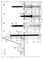
- FIG. 1 the production of a in four phases a) to d) shown column according to the invention.
- a vertically cut Soil with the surface 11 has a non-load-bearing and non-supportable top layer 12 (soft layer), below an at least supportable bottom layer 13 and finally underneath a well-bearing floor layer 14.
- a vibrator 17 is guided, which is a feed hopper 18 passes through for material introduction.
- the jogger tip is vibrated into the load-bearing floor layer 14.
- dashed lines is a thickened column base 19 shown, the optional in a first step Vibratory compaction or stuffing compaction from rolling material - with or without binder surcharge - can be generated.
- the vibrator 17 is already complete pulled, whereby - on the optional column base 19 - a lower column section using vibrating or tamping technology 20 is built from rolly material that extends into the load-bearing Bottom layer 14 extends radially directly from the bottom the supportable bottom layer 13 is supported.
- This lower one Column section 20 extends into the unsustainable top Bottom layer 12 slightly into it, while the rest Displacement hole 21 can be seen in this bottom layer.
- a tube 22 is coaxial which has inner drivers 24 at the lower end, that of driver pin 23 at the lower end of the vibrator can be taken.
- the illustration d) shows that the final Pulling the vibrator 17 the sheathing tube 22 over the vibrator has been filled with rolling material that is in suitable Dimensions can be compressed, creating an upper column section 26 arose with radial support through the sheathing tube 22 is.
- the cladding tube open here used below 22 could also be closed at the bottom by a cover Pipe set in the lower column section 20 become.
- the geotextile hose 27 to form an upper column section 28 with rolled material filled, the hose 27 by radial expansion Support forces can build up and the filling material essentially demarcated from the ground.
- FIG. 3 shows essentially the same device situation in three phases and the same soil stratification as in the figures 1 and 2 shown.
- the same details are the same Provide reference numbers.
- a solid sheathing tube is used 22 'during the first vibrating process of the vibrator 17 according to illustration a) at a distance from the vibrator tip pushed coaxially onto the vibrator and brought down into the ground.
- the corresponding driver means 23, 24 are located at a corresponding distance from the vibrator tip.
- the cladding tube 22 'already has reaches its intended position that the non-supportive Soil layer 12 penetrates and into the at least Sustainable bottom layer 13 protrudes.
- the vibrator 17 is already inside of the cladding tube 22 'withdrawn after being pulled a lower column section 20 in the area of at least Sustainable bottom layer 13 has generated the radially immediately is supported by the ground.
- the vibrator 17 is completely out of the Wrapping tube 22 'pulled up, the wrap tube 22 'to form an upper column section 28 is filled with rolly material that differs from the material here of the lower column section 20 differs.
- FIG. 4 is essentially the same terrain and equipment situation and the same sequence of processes as in FIG. 3 shown. The same details are given the same reference numbers Mistake. In this respect, reference is made to the description of FIG. 3 taken.
- a rigid cladding tube is here a less recognizable geotextile tube open at the bottom 27 'pulled over the middle section of the vibrator 17 and so far taken down that he was the unsustainable bottom layer 12 penetrates and with the lower end in the least Sustainable bottom layer 13 protrudes.
- the pillar foot 19 is already finished in the area of the load-bearing floor layer 14 posed.
- the common principle can be seen in the illustrations to reduce costs and reduce material consumption additional covering for the column material only in the area not at least supportable upper soil layers. This reduces the need for support bodies by length as well as the consumption of filling material in the area of non-supportive layers.
- the load is transferred via the entire column body into the lower layers of the floor, load transfer in the area of the lower column section via jacket friction in addition to the bearing load of the column base or as an exclusive force transmission into the ground becomes possible.
Applications Claiming Priority (2)
| Application Number | Priority Date | Filing Date | Title |
|---|---|---|---|
| DE10108602 | 2001-02-22 | ||
| DE10108602A DE10108602A1 (de) | 2001-02-22 | 2001-02-22 | Verfahren zum Herstellen von Säulen |
Publications (3)
| Publication Number | Publication Date |
|---|---|
| EP1234916A2 true EP1234916A2 (fr) | 2002-08-28 |
| EP1234916A3 EP1234916A3 (fr) | 2002-12-18 |
| EP1234916B1 EP1234916B1 (fr) | 2006-05-24 |
Family
ID=7675158
Family Applications (1)
| Application Number | Title | Priority Date | Filing Date |
|---|---|---|---|
| EP02003803A Expired - Lifetime EP1234916B1 (fr) | 2001-02-22 | 2002-02-20 | Méthode pour construire des colonnes |
Country Status (3)
| Country | Link |
|---|---|
| EP (1) | EP1234916B1 (fr) |
| AT (1) | ATE327389T1 (fr) |
| DE (2) | DE10108602A1 (fr) |
Cited By (13)
| Publication number | Priority date | Publication date | Assignee | Title |
|---|---|---|---|---|
| WO2006127571A2 (fr) | 2005-05-20 | 2006-11-30 | Geopier Foundation Company, Inc. | Mandrin a fentes pour pieux a refoulement lateral et procede d'utilisation |
| WO2007041250A2 (fr) | 2005-09-29 | 2007-04-12 | Geopier Foundation Company | Tetes de damage et procede d'utilisation |
| WO2011001297A1 (fr) * | 2009-06-30 | 2011-01-06 | Russet Trading & Investment 24 (Pty) Ltd | Procédé pour construire une colonne |
| US8128319B2 (en) | 2008-07-29 | 2012-03-06 | Geopier Foundation Company, Inc. | Shielded tamper and method of use for making aggregate columns |
| WO2012037089A2 (fr) | 2010-09-13 | 2012-03-22 | Geopier Foundation Company, Inc. | Coques extensibles et procédés associés pour la construction d'un pilier porteur |
| CN102444119A (zh) * | 2011-09-19 | 2012-05-09 | 刘清洁 | 在卵石层、园砾层、砂层中施工沉管灌注桩的方法 |
| WO2011098081A3 (fr) * | 2010-02-09 | 2012-06-28 | Wilhelm Degen | Procédé de production de colonnes de matériau et dispositif vibrant comprenant une unité de levage |
| US8562258B2 (en) | 2008-07-29 | 2013-10-22 | Geopier Foundation Company, Inc. | Shielded tamper and method of use for making aggregate columns |
| WO2013175208A2 (fr) * | 2012-05-23 | 2013-11-28 | Scotrenewalables Tidal Power Limited | Procédé de formation d'un dispositif de massif d'ancrage en béton |
| EP3118375A1 (fr) | 2015-07-13 | 2017-01-18 | Dura Vermeer Beton & Waterbouw B.V. | Procédé pour améliorer la stabilité interne d'une berge |
| US10513831B2 (en) | 2010-09-13 | 2019-12-24 | Geopier Foundation Company, Inc. | Open-end extensible shells and related methods for constructing a support pier |
| CN111851479A (zh) * | 2020-07-30 | 2020-10-30 | 陕西龙海新创基础工程有限公司 | 一种在砂层或碎石层中施工沉管夯扩灌注桩的方法 |
| US10858796B2 (en) | 2015-07-27 | 2020-12-08 | Geopier Foundation Company, Inc. | Extensible shells and related methods for constructing a ductile support pier |
Families Citing this family (8)
| Publication number | Priority date | Publication date | Assignee | Title |
|---|---|---|---|---|
| US8152415B2 (en) | 2000-06-15 | 2012-04-10 | Geopier Foundation Company, Inc. | Method and apparatus for building support piers from one or more successive lifts formed in a soil matrix |
| DE20120859U1 (de) * | 2001-12-27 | 2003-05-08 | Kirchner Martin E | Vorrichtung zur Herstellung von textilummantelten Schüttbaustoffsäulen im Erdreich |
| DE10218330A1 (de) * | 2002-04-24 | 2003-11-13 | Vibroflotation B V | Verfahren und Vorrichtung zur Herstellung von Materialsäulen im Boden |
| DE10242264B4 (de) * | 2002-09-12 | 2005-02-24 | Josef Möbius Bau-Gesellschaft (GmbH & Co.) | Verfahren zur Herstellung eines interaktiven Tragsystems aus geotextilummantelten Sandsäulen und den anstehenden Böden zur Abtragung von Bauwerks- und Verkehrslasten bei wenig tragfähigem Untergrund |
| DE10310727B4 (de) * | 2003-03-12 | 2007-09-13 | Bauer Spezialtiefbau Gmbh | Füllrohr |
| DE10333613B4 (de) * | 2003-07-24 | 2011-06-30 | Keller Grundbau GmbH, 63067 | Verbesserung einer Weichschicht |
| DE102005001227A1 (de) | 2005-01-10 | 2006-07-20 | Keller Grundbau Gmbh | Baugrundverbesserung durch Hybrid- Säulen |
| DE102006033957B4 (de) * | 2006-07-22 | 2010-04-15 | Josef Möbius Bau-Aktiengesellschaft | Verfahren zur Erstellung von geotextilummantelten Säulen aus körnigem bzw. rolligem Material |
Citations (2)
| Publication number | Priority date | Publication date | Assignee | Title |
|---|---|---|---|---|
| DE4408173A1 (de) | 1994-03-10 | 1995-09-14 | Moebius Josef Bau | Verfahren zur Stabilisierung des Untergrundes und zur Abtragung von Bauwerks- und Verkehrslasten |
| EP0900883A1 (fr) | 1997-09-04 | 1999-03-10 | JOSEF MÖBIUS BAUGESELLSCHAFT (GmbH & Co.) | Procédé et enveloppe pour former une colonne dans le sol, pour supporter le poids d'une structure ou de la circulation |
Family Cites Families (5)
| Publication number | Priority date | Publication date | Assignee | Title |
|---|---|---|---|---|
| DE537358C (de) * | 1931-11-02 | Emil Gerbracht | Gruendungsverfahren in wenig tragfaehigem Boden unter Anwendung von Betonpfaehlen | |
| GB515120A (en) * | 1938-05-24 | 1939-11-27 | Alfred Hiley | Improved method of and means for forming concrete piles |
| AT296168B (de) * | 1968-11-05 | 1972-02-10 | Ignaz Dipl Ing Zeissl | Verfahren zur Herstellung eines abschnittsweise hergestellten Ortbetonpfahles mittels eines Dieselrammbären und eines Rammrohres |
| SE506023C2 (sv) * | 1992-10-09 | 1997-11-03 | Anders Mohss | Fristående vertikal gjutform för exempelvis plintar och pelare |
| DE29611427U1 (de) * | 1996-07-01 | 1996-09-05 | Moebius Josef Bau | Rohrförmiger Verdrängungskörper |
-
2001
- 2001-02-22 DE DE10108602A patent/DE10108602A1/de not_active Withdrawn
-
2002
- 2002-02-20 EP EP02003803A patent/EP1234916B1/fr not_active Expired - Lifetime
- 2002-02-20 DE DE50206850T patent/DE50206850D1/de not_active Expired - Lifetime
- 2002-02-20 AT AT02003803T patent/ATE327389T1/de active
Patent Citations (2)
| Publication number | Priority date | Publication date | Assignee | Title |
|---|---|---|---|---|
| DE4408173A1 (de) | 1994-03-10 | 1995-09-14 | Moebius Josef Bau | Verfahren zur Stabilisierung des Untergrundes und zur Abtragung von Bauwerks- und Verkehrslasten |
| EP0900883A1 (fr) | 1997-09-04 | 1999-03-10 | JOSEF MÖBIUS BAUGESELLSCHAFT (GmbH & Co.) | Procédé et enveloppe pour former une colonne dans le sol, pour supporter le poids d'une structure ou de la circulation |
Cited By (22)
| Publication number | Priority date | Publication date | Assignee | Title |
|---|---|---|---|---|
| EP1888848A4 (fr) * | 2005-05-20 | 2009-12-23 | Geopier Found Co Inc | Mandrin a fentes pour pieux a refoulement lateral et procede d'utilisation |
| WO2006127571A2 (fr) | 2005-05-20 | 2006-11-30 | Geopier Foundation Company, Inc. | Mandrin a fentes pour pieux a refoulement lateral et procede d'utilisation |
| EP1888848A2 (fr) * | 2005-05-20 | 2008-02-20 | Geopier Foundation Company, Inc. | Mandrin a fentes pour pieux a refoulement lateral et procede d'utilisation |
| EP1937900A2 (fr) * | 2005-09-29 | 2008-07-02 | Geopier Foundation Company | Tetes de damage pyramidales ou coniques, et procede d'utilisation pour la realisation de contreforts d'agregats dames |
| EP1937900A4 (fr) * | 2005-09-29 | 2008-10-15 | Geopier Foundation Company | Tetes de damage pyramidales ou coniques, et procede d'utilisation pour la realisation de contreforts d'agregats dames |
| US7488139B2 (en) | 2005-09-29 | 2009-02-10 | Geopier Foundation Company, Inc. | Pyramidal or conical shaped tamper heads and method of use for making rammed aggregate piers |
| WO2007041250A2 (fr) | 2005-09-29 | 2007-04-12 | Geopier Foundation Company | Tetes de damage et procede d'utilisation |
| US8128319B2 (en) | 2008-07-29 | 2012-03-06 | Geopier Foundation Company, Inc. | Shielded tamper and method of use for making aggregate columns |
| US8562258B2 (en) | 2008-07-29 | 2013-10-22 | Geopier Foundation Company, Inc. | Shielded tamper and method of use for making aggregate columns |
| WO2011001297A1 (fr) * | 2009-06-30 | 2011-01-06 | Russet Trading & Investment 24 (Pty) Ltd | Procédé pour construire une colonne |
| WO2011098081A3 (fr) * | 2010-02-09 | 2012-06-28 | Wilhelm Degen | Procédé de production de colonnes de matériau et dispositif vibrant comprenant une unité de levage |
| EP2616591A4 (fr) * | 2010-09-13 | 2017-03-01 | Geopier Foundation Company, Inc. | Coques extensibles et procédés associés pour la construction d'un pilier porteur |
| WO2012037089A2 (fr) | 2010-09-13 | 2012-03-22 | Geopier Foundation Company, Inc. | Coques extensibles et procédés associés pour la construction d'un pilier porteur |
| US10513831B2 (en) | 2010-09-13 | 2019-12-24 | Geopier Foundation Company, Inc. | Open-end extensible shells and related methods for constructing a support pier |
| CN102444119A (zh) * | 2011-09-19 | 2012-05-09 | 刘清洁 | 在卵石层、园砾层、砂层中施工沉管灌注桩的方法 |
| WO2013175208A3 (fr) * | 2012-05-23 | 2014-01-30 | Scotrenewalables Tidal Power Limited | Procédé de formation d'un dispositif de massif d'ancrage en béton |
| WO2013175208A2 (fr) * | 2012-05-23 | 2013-11-28 | Scotrenewalables Tidal Power Limited | Procédé de formation d'un dispositif de massif d'ancrage en béton |
| EP3118375A1 (fr) | 2015-07-13 | 2017-01-18 | Dura Vermeer Beton & Waterbouw B.V. | Procédé pour améliorer la stabilité interne d'une berge |
| US10858796B2 (en) | 2015-07-27 | 2020-12-08 | Geopier Foundation Company, Inc. | Extensible shells and related methods for constructing a ductile support pier |
| US11479935B2 (en) | 2015-07-27 | 2022-10-25 | Geopier Foundation Company, Inc. | Extensible shells and related methods for constructing a ductile support pier |
| CN111851479A (zh) * | 2020-07-30 | 2020-10-30 | 陕西龙海新创基础工程有限公司 | 一种在砂层或碎石层中施工沉管夯扩灌注桩的方法 |
| WO2022021469A1 (fr) * | 2020-07-30 | 2022-02-03 | 陕西龙海新创基础工程有限公司 | Procédé de construction d'un pieu coulé in situ introduit et étendu par creusement de pipeline dans une couche de sable ou de gravier |
Also Published As
| Publication number | Publication date |
|---|---|
| DE10108602A1 (de) | 2002-09-12 |
| EP1234916A3 (fr) | 2002-12-18 |
| EP1234916B1 (fr) | 2006-05-24 |
| DE50206850D1 (de) | 2006-06-29 |
| ATE327389T1 (de) | 2006-06-15 |
Similar Documents
| Publication | Publication Date | Title |
|---|---|---|
| EP1234916A2 (fr) | Méthode pour construire des colonnes | |
| EP1688543B1 (fr) | Amélioration de la consolidation du sol par des colonnes hybrides | |
| DE1634470A1 (de) | Gruendungspfahl | |
| EP1009884B1 (fr) | Procede et enveloppe pour produire une colonne de terre servant a supporter des charges d'ouvrage et des charges mobiles | |
| DE3445965A1 (de) | Verdichtende tiefgruendung, verfahren und vorrichtung zu deren herstellen | |
| DE4408173C2 (de) | Verfahren zur Stabilisierung des Untergrundes und zur Abtragung von Bauwerks- und Verkehrslasten | |
| DE19518830B4 (de) | Verfahren zur Stabilisierung des Untergrundes und zur Abtragung von Bauwerks- und Verkehrslasten | |
| EP0788572B1 (fr) | Procede de reprise en sous-oeuvre de batiments | |
| EP1134319A2 (fr) | Procédé et dispositif pour l'obtention d'un pieu en béton coulé in situ | |
| DE3318050C2 (fr) | ||
| DE102005029364B4 (de) | Fertigteilpfahl sowie dazugehöriges Verfahren zur Bauwerksgründung | |
| DE102005008679A1 (de) | Verfahren zur Herstellung von Rammpfählen mit mindestens einem doppelwandigen Rammrohr | |
| DE10025966C2 (de) | Stützschlauch-Säulen | |
| DE102012004980A1 (de) | Verfahren zur Stabilisierung des Untergrunds und zur Abtragung von Bauwerks- und Verkehrslasten in standfeste Bereiche | |
| DE10242264B4 (de) | Verfahren zur Herstellung eines interaktiven Tragsystems aus geotextilummantelten Sandsäulen und den anstehenden Böden zur Abtragung von Bauwerks- und Verkehrslasten bei wenig tragfähigem Untergrund | |
| DE102021116487B3 (de) | Geotextilummantelte Flüssigbodensäulen | |
| EP1273713B1 (fr) | Méthode pour construire des colonnes de matériaux pour améliorer la consolidation du sol | |
| DE3033715A1 (de) | Verfahren zur untergrundverbesserung und dazu dienender gruendungspfahl, -anker o.dgl. | |
| DE1910556A1 (de) | Verfahren zur Herstellung von Gruendungspfaehlen aus Ortbeton mit Erweiterungen des Pfahlschaftes und des Pfahlfusses,sowie Innenschalung zur Durchfuehrung des Verfahrens | |
| EP3789469B1 (fr) | Procédé de fabrication d'un composant de base | |
| DE3324509A1 (de) | Verfahren zur herstellung von bohrpfaehlen mit verbesserter tragfaehigkeit | |
| DE2303056A1 (de) | Vorrichtung zum bau von gruendungen aus betonpfaehlen mit sockel und rippen | |
| AT330095B (de) | Vorrichtung zur herstellung eines ortsbetonrammpfahles | |
| DE10338171B4 (de) | Verfahren zum Einbringen eines schlanken Bodenpfahls und nach diesem Verfahren hergestellter Bodenpfahl | |
| DE2851619A1 (de) | Verfahren zum herstellen eines ortbetonpfahles |
Legal Events
| Date | Code | Title | Description |
|---|---|---|---|
| PUAI | Public reference made under article 153(3) epc to a published international application that has entered the european phase |
Free format text: ORIGINAL CODE: 0009012 |
|
| AK | Designated contracting states |
Kind code of ref document: A2 Designated state(s): AT BE CH CY DE DK ES FI FR GB GR IE IT LI LU MC NL PT SE TR |
|
| AX | Request for extension of the european patent |
Free format text: AL;LT;LV;MK;RO;SI |
|
| RIN1 | Information on inventor provided before grant (corrected) |
Inventor name: TRUNK, ULRICH, DR. Inventor name: VOELZKE, BURKHARD Inventor name: ASCHENBRENNER, GABRIELE Inventor name: ZIMMERMANN, KAI-UWE |
|
| PUAL | Search report despatched |
Free format text: ORIGINAL CODE: 0009013 |
|
| AK | Designated contracting states |
Kind code of ref document: A3 Designated state(s): AT BE CH CY DE DK ES FI FR GB GR IE IT LI LU MC NL PT SE TR |
|
| AX | Request for extension of the european patent |
Free format text: AL;LT;LV;MK;RO;SI |
|
| RIC1 | Information provided on ipc code assigned before grant |
Free format text: 7E 02D 3/08 A, 7E 02D 5/38 B, 7E 02D 5/44 B, 7E 02D 5/48 B, 7E 02D 5/66 B |
|
| 17P | Request for examination filed |
Effective date: 20030215 |
|
| AKX | Designation fees paid |
Designated state(s): AT BE CH CY DE DK ES FI FR GB GR IE IT LI LU MC NL PT SE TR |
|
| AXX | Extension fees paid |
Extension state: SI Payment date: 20030312 |
|
| GRAP | Despatch of communication of intention to grant a patent |
Free format text: ORIGINAL CODE: EPIDOSNIGR1 |
|
| GRAS | Grant fee paid |
Free format text: ORIGINAL CODE: EPIDOSNIGR3 |
|
| GRAA | (expected) grant |
Free format text: ORIGINAL CODE: 0009210 |
|
| AK | Designated contracting states |
Kind code of ref document: B1 Designated state(s): AT BE CH CY DE DK ES FI FR GB GR IE IT LI LU MC NL PT SE TR |
|
| AX | Request for extension of the european patent |
Extension state: SI |
|
| PG25 | Lapsed in a contracting state [announced via postgrant information from national office to epo] |
Ref country code: IT Free format text: LAPSE BECAUSE OF FAILURE TO SUBMIT A TRANSLATION OF THE DESCRIPTION OR TO PAY THE FEE WITHIN THE PRESCRIBED TIME-LIMIT;WARNING: LAPSES OF ITALIAN PATENTS WITH EFFECTIVE DATE BEFORE 2007 MAY HAVE OCCURRED AT ANY TIME BEFORE 2007. THE CORRECT EFFECTIVE DATE MAY BE DIFFERENT FROM THE ONE RECORDED. Effective date: 20060524 Ref country code: IE Free format text: LAPSE BECAUSE OF FAILURE TO SUBMIT A TRANSLATION OF THE DESCRIPTION OR TO PAY THE FEE WITHIN THE PRESCRIBED TIME-LIMIT Effective date: 20060524 Ref country code: GB Free format text: LAPSE BECAUSE OF FAILURE TO SUBMIT A TRANSLATION OF THE DESCRIPTION OR TO PAY THE FEE WITHIN THE PRESCRIBED TIME-LIMIT Effective date: 20060524 Ref country code: FI Free format text: LAPSE BECAUSE OF FAILURE TO SUBMIT A TRANSLATION OF THE DESCRIPTION OR TO PAY THE FEE WITHIN THE PRESCRIBED TIME-LIMIT Effective date: 20060524 |
|
| REG | Reference to a national code |
Ref country code: GB Ref legal event code: FG4D Free format text: NOT ENGLISH |
|
| REG | Reference to a national code |
Ref country code: CH Ref legal event code: EP |
|
| REG | Reference to a national code |
Ref country code: IE Ref legal event code: FG4D Free format text: LANGUAGE OF EP DOCUMENT: GERMAN |
|
| REF | Corresponds to: |
Ref document number: 50206850 Country of ref document: DE Date of ref document: 20060629 Kind code of ref document: P |
|
| REG | Reference to a national code |
Ref country code: CH Ref legal event code: NV Representative=s name: PA ALDO ROEMPLER |
|
| PG25 | Lapsed in a contracting state [announced via postgrant information from national office to epo] |
Ref country code: SE Free format text: LAPSE BECAUSE OF FAILURE TO SUBMIT A TRANSLATION OF THE DESCRIPTION OR TO PAY THE FEE WITHIN THE PRESCRIBED TIME-LIMIT Effective date: 20060824 Ref country code: DK Free format text: LAPSE BECAUSE OF FAILURE TO SUBMIT A TRANSLATION OF THE DESCRIPTION OR TO PAY THE FEE WITHIN THE PRESCRIBED TIME-LIMIT Effective date: 20060824 |
|
| PG25 | Lapsed in a contracting state [announced via postgrant information from national office to epo] |
Ref country code: ES Free format text: LAPSE BECAUSE OF FAILURE TO SUBMIT A TRANSLATION OF THE DESCRIPTION OR TO PAY THE FEE WITHIN THE PRESCRIBED TIME-LIMIT Effective date: 20060904 |
|
| PG25 | Lapsed in a contracting state [announced via postgrant information from national office to epo] |
Ref country code: PT Free format text: LAPSE BECAUSE OF FAILURE TO SUBMIT A TRANSLATION OF THE DESCRIPTION OR TO PAY THE FEE WITHIN THE PRESCRIBED TIME-LIMIT Effective date: 20061024 |
|
| GBV | Gb: ep patent (uk) treated as always having been void in accordance with gb section 77(7)/1977 [no translation filed] |
Effective date: 20060524 |
|
| REG | Reference to a national code |
Ref country code: IE Ref legal event code: FD4D |
|
| PG25 | Lapsed in a contracting state [announced via postgrant information from national office to epo] |
Ref country code: MC Free format text: LAPSE BECAUSE OF NON-PAYMENT OF DUE FEES Effective date: 20070228 |
|
| PLBE | No opposition filed within time limit |
Free format text: ORIGINAL CODE: 0009261 |
|
| STAA | Information on the status of an ep patent application or granted ep patent |
Free format text: STATUS: NO OPPOSITION FILED WITHIN TIME LIMIT |
|
| 26N | No opposition filed |
Effective date: 20070227 |
|
| EN | Fr: translation not filed | ||
| BERE | Be: lapsed |
Owner name: KELLER GRUNDBAU G.M.B.H. Effective date: 20070228 |
|
| PG25 | Lapsed in a contracting state [announced via postgrant information from national office to epo] |
Ref country code: BE Free format text: LAPSE BECAUSE OF NON-PAYMENT OF DUE FEES Effective date: 20070228 |
|
| PG25 | Lapsed in a contracting state [announced via postgrant information from national office to epo] |
Ref country code: GR Free format text: LAPSE BECAUSE OF FAILURE TO SUBMIT A TRANSLATION OF THE DESCRIPTION OR TO PAY THE FEE WITHIN THE PRESCRIBED TIME-LIMIT Effective date: 20060825 Ref country code: FR Free format text: LAPSE BECAUSE OF FAILURE TO SUBMIT A TRANSLATION OF THE DESCRIPTION OR TO PAY THE FEE WITHIN THE PRESCRIBED TIME-LIMIT Effective date: 20070309 |
|
| REG | Reference to a national code |
Ref country code: CH Ref legal event code: PCAR Free format text: ALDO ROEMPLER PATENTANWALT;BRENDENWEG 11 POSTFACH 154;9424 RHEINECK (CH) |
|
| PG25 | Lapsed in a contracting state [announced via postgrant information from national office to epo] |
Ref country code: FR Free format text: LAPSE BECAUSE OF FAILURE TO SUBMIT A TRANSLATION OF THE DESCRIPTION OR TO PAY THE FEE WITHIN THE PRESCRIBED TIME-LIMIT Effective date: 20060524 |
|
| PG25 | Lapsed in a contracting state [announced via postgrant information from national office to epo] |
Ref country code: LU Free format text: LAPSE BECAUSE OF NON-PAYMENT OF DUE FEES Effective date: 20070220 Ref country code: CY Free format text: LAPSE BECAUSE OF FAILURE TO SUBMIT A TRANSLATION OF THE DESCRIPTION OR TO PAY THE FEE WITHIN THE PRESCRIBED TIME-LIMIT Effective date: 20060524 |
|
| PG25 | Lapsed in a contracting state [announced via postgrant information from national office to epo] |
Ref country code: TR Free format text: LAPSE BECAUSE OF FAILURE TO SUBMIT A TRANSLATION OF THE DESCRIPTION OR TO PAY THE FEE WITHIN THE PRESCRIBED TIME-LIMIT Effective date: 20060524 |
|
| REG | Reference to a national code |
Ref country code: DE Ref legal event code: R084 Ref document number: 50206850 Country of ref document: DE |
|
| PGFP | Annual fee paid to national office [announced via postgrant information from national office to epo] |
Ref country code: NL Payment date: 20200220 Year of fee payment: 19 Ref country code: DE Payment date: 20200229 Year of fee payment: 19 Ref country code: AT Payment date: 20200218 Year of fee payment: 19 |
|
| PGFP | Annual fee paid to national office [announced via postgrant information from national office to epo] |
Ref country code: CH Payment date: 20200224 Year of fee payment: 19 |
|
| REG | Reference to a national code |
Ref country code: DE Ref legal event code: R119 Ref document number: 50206850 Country of ref document: DE |
|
| REG | Reference to a national code |
Ref country code: AT Ref legal event code: MM01 Ref document number: 327389 Country of ref document: AT Kind code of ref document: T Effective date: 20210220 |
|
| PG25 | Lapsed in a contracting state [announced via postgrant information from national office to epo] |
Ref country code: CH Free format text: LAPSE BECAUSE OF NON-PAYMENT OF DUE FEES Effective date: 20210228 Ref country code: AT Free format text: LAPSE BECAUSE OF NON-PAYMENT OF DUE FEES Effective date: 20210220 Ref country code: LI Free format text: LAPSE BECAUSE OF NON-PAYMENT OF DUE FEES Effective date: 20210228 |
|
| REG | Reference to a national code |
Ref country code: NL Ref legal event code: MM Effective date: 20210301 |
|
| PG25 | Lapsed in a contracting state [announced via postgrant information from national office to epo] |
Ref country code: NL Free format text: LAPSE BECAUSE OF NON-PAYMENT OF DUE FEES Effective date: 20210301 |
|
| PG25 | Lapsed in a contracting state [announced via postgrant information from national office to epo] |
Ref country code: DE Free format text: LAPSE BECAUSE OF NON-PAYMENT OF DUE FEES Effective date: 20210901 |