EP1234916B1 - Méthode pour construire des colonnes - Google Patents
Méthode pour construire des colonnes Download PDFInfo
- Publication number
- EP1234916B1 EP1234916B1 EP02003803A EP02003803A EP1234916B1 EP 1234916 B1 EP1234916 B1 EP 1234916B1 EP 02003803 A EP02003803 A EP 02003803A EP 02003803 A EP02003803 A EP 02003803A EP 1234916 B1 EP1234916 B1 EP 1234916B1
- Authority
- EP
- European Patent Office
- Prior art keywords
- envelope
- soil
- column
- process according
- column portion
- Prior art date
- Legal status (The legal status is an assumption and is not a legal conclusion. Google has not performed a legal analysis and makes no representation as to the accuracy of the status listed.)
- Expired - Lifetime
Links
Images

Classifications
-
- E—FIXED CONSTRUCTIONS
- E02—HYDRAULIC ENGINEERING; FOUNDATIONS; SOIL SHIFTING
- E02D—FOUNDATIONS; EXCAVATIONS; EMBANKMENTS; UNDERGROUND OR UNDERWATER STRUCTURES
- E02D3/00—Improving or preserving soil or rock, e.g. preserving permafrost soil
- E02D3/12—Consolidating by placing solidifying or pore-filling substances in the soil
- E02D3/123—Consolidating by placing solidifying or pore-filling substances in the soil and compacting the soil
-
- E—FIXED CONSTRUCTIONS
- E02—HYDRAULIC ENGINEERING; FOUNDATIONS; SOIL SHIFTING
- E02D—FOUNDATIONS; EXCAVATIONS; EMBANKMENTS; UNDERGROUND OR UNDERWATER STRUCTURES
- E02D3/00—Improving or preserving soil or rock, e.g. preserving permafrost soil
- E02D3/02—Improving by compacting
- E02D3/08—Improving by compacting by inserting stones or lost bodies, e.g. compaction piles
-
- E—FIXED CONSTRUCTIONS
- E02—HYDRAULIC ENGINEERING; FOUNDATIONS; SOIL SHIFTING
- E02D—FOUNDATIONS; EXCAVATIONS; EMBANKMENTS; UNDERGROUND OR UNDERWATER STRUCTURES
- E02D7/00—Methods or apparatus for placing sheet pile bulkheads, piles, mouldpipes, or other moulds
- E02D7/02—Placing by driving
- E02D7/06—Power-driven drivers
- E02D7/14—Components for drivers inasmuch as not specially for a specific driver construction
Definitions
- the invention relates to a method for producing columns in soils with at least one non-load-bearing bottom layer for the purpose of ground improvement or stabilization.
- methods There are a variety of methods are known, according to which insufficiently sustainable ground is improved by the incorporation of columns arranged in a grid.
- Insufficiently sustainable ground is improved by the incorporation of columns arranged in a grid.
- different mechanisms of action to advantage On the one hand can be done by deep-reaching columnar body load transfer into deeper-lying viable layers;
- a soil compaction between the column bodies can take place;
- soil water can be extracted from cohesive soils.
- the invention has for its object to propose a method for the production of columns, which leads to time-consuming and cost advantages in the application of low-lying viable or at least supportive layers and non-sustainable surface layers or intermediate layers.
- the solution to this problem consists in a method for producing columns in soils with at least one non-load-bearing bottom layer for the purpose of ground improvement or stabilization, with the following method steps for producing one of the columns, a displacement device, in particular a deep vibrator with lock tube or a displacement tube with closure, is vibrated from the bottom surface through the at least one non-viable bottom layer into a viable or at least sustainable soil layer, a directly supported by an at least supportable bottom layers lower column section, in particular by means of the displacement device, from bottom to top of rolling material constructed, a tubular or tubular casing is from the bottom surface, at least one non-sustainable bottom layer passing through, built into the lower column section extends in sufficient depth, the envelope is Kurs Schmu ng of an upper supported by the sheath Column section filled with rolling material.
- a thickened column foot of rolligem material in particular by means of the displacement device, first installed in the load-bearing soil layer on which then the lower column section is constructed.
- the main advantage of the method is therefore to use as far as possible in conventional stuffing or vibrating produced uncased column body, which can rest on a particular embedded in a stable or at least supportive layer thickened column base, and the stability of the column body by using a sheath exclusively to a depth from which there is sufficient continuous support capability down to the lower end of the column.
- the present stratification is to be determined by previous excavation drilling or other foundation exploration methods.
- the columns according to the invention are characterized even with the use of binder-free material even with the expected loads thereby dimensionally stable, that the envelope in the unstable floor area is designed so that it absorbs the expected stress conditions with minimal radial deformation and thus the loads in the un-threatened lower column section and the pedestal can be registered without damage.
- the envelope After a first process implementation, the envelope after a first shaking and pulling the displacer - after production of the lower column section - at the coaxially mounted on the lower end of this and drilled at a second shaking the displacement device to its intended depth.
- the process sequence is in this case initially the same as in the production of conventional vibrating or Stopf yarnen, which as already mentioned, when pulling the lower column section is made only zoom up to a first soft layer and the displacement device is then pulled to leave a displacement hole. In this case, the introduction of support liquid may be required.
- the envelope is mounted on the displacement device and drawn in a second additional shaking with this in the existing open Rüttelö réelle and partially introduced into the existing lower column section.
- the displacer can be drawn by immediately filling the casing and compacting the filler material (contractor method) or drawing it without introducing filler material, which can then be filled from the top end of the casing (from the bottom surface).
- the casing is mounted at a distance from the lower end of the displacer coaxially on this and already at a first shaking of the displacement device - made before the production of the lower column section - with this and separated while pulling from this.
- the latter separation can be done automatically, if in one direction effective entrainment means are used.
- special coupling means separable from the ground surface may be provided.
- the enclosure is brought to the intended depth, so that it extends down to at least sustainable soil layers.
- the material of the column can be introduced in a single operation from bottom to top be carried out, wherein in the upper region, the radial support is carried out by the already installed sheath. Accelerated pulling of the displacement device in the region of the enclosure and filling of filling material in the upper column section from the bottom surface is here less sensible, but not excluded.
- binderless, mobile material - rock, gravel, gravel, sand - is appropriate in those cases where the columns are also said to have vertical drainage, i. when water permeability in the vertical direction is to be guaranteed, or in which the same is not disadvantageous.
- binder-containing rolligem material - mortar, concrete - is preferable, especially when higher loads are to be removed and / or water exchange between different water-bearing layers is to be avoided.
- a geotextile tube be it with nonwoven composite portion or without fleece portion, can be used as the sheathing.
- the tube sheaths used are usually designed as open-bottom tube.
- the present invention finds application wherever the displacement or compaction of the soil during the introduction of stuffing or vibrating columns, the required support stress or reaction stress in upper soil layers - surface layers or intermediate layers - is not achieved and the soil for the functionality of the column required radial support can not build up or a horizontal running of the mortar or concrete during insertion before its hardening can not prevent.
- the column In the lying directly above the lower end of the column soil layers in which there is sufficient radial support throughout, the column is prepared according to known techniques without additional coating.
- a sufficiently load-bearing or at least supportable layer must be present, in which initially a pedestal can be stuffed out of roll-like material.
- a pedestal can be stuffed out of roll-like material.
- gravel, gravel, sand, mortar or concrete, d. H. case-hardened material with or without addition of binder is used.
- binder-containing material By using binder-containing material, a vertical flow can be reduced or prevented, so that a connection between different groundwater floors remains suppressed.
- the column is according to the invention with a covering made of tubes or geotextile tubes.
- the upper pillar portion (with wrapper) can be filled and stuffed with coarse material with or without binder additive, usually gravel, crushed stone, sand, mortar or concrete, regardless of the embodiment of the lower pillar portion (without wrapper).
- an envelope made of a material that undergoes significant elongation during load application, so in particular in a geotextile envelope, it is advantageous to compress the filler in the envelope immediately during column production, so that no significant additional strains occur during load application and only construction-compatible settlements are to be accepted later.
- the wrapper may additionally serve to prevent or substantially prevent a change or chemical reaction of the column material with the soil, the soil moisture, the groundwater, for example, to reduce or completely avoid a change in the pH in the surrounding soil by the introduction of binder.
- viable columns can be prepared, which can be charged immediately or after hardening of the binder optionally used. Due to their method of manufacture, only small settlements are expected when applying loads.
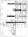
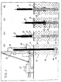
- FIG. 1 shows in four phases a) to d) the preparation of a column according to the invention.
- a vertically cut ground with the surface 11 has a non-load-bearing and unsupportable upper soil layer 12 (soft layer), including an at least supportable soil layer 13 and finally including a well-soil layer 14th
- a brought on the surface 11 in position caterpillar 15 is shown in the erected leader 16, a vibrator 17 is guided, which passes through a feed hopper 18 for material introduction.
- the Rüttlerspitze is shaken to the viable soil layer 14.
- Dashed lines show a thickened column foot 19, which can optionally be produced in a first step by vibratory compaction or stuffing compaction of a rolling material, with or without binder aggregate.
- the vibrator 17 is already fully drawn, wherein - on the optionally existing column foot 19 - in vibrating or stuffing a lower column section 20 is made of rolligem material that extends into the viable bottom layer 14 and radially directly from the bottom of supportive soil layer 13 is supported.
- This lower column section 20 protrudes slightly into the unsupportable upper bottom layer 12, while otherwise the displacement hole 21 can be seen in this bottom layer.
- a tube 22 is coaxial mounted, which has inner driver 24 at the lower end, which can be taken by driving pin 23 at the bottom of the vibrator.
- the geotextile tube 27 is filled with rolling material to form an upper column section 28, whereby the tube 27 can build up supporting forces by radial expansion and delimits the filling material essentially against the pending floor.
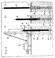
- FIG. 3 substantially the same device situation and the same bottom layering as in FIGS. 1 and 2 are shown in three phases. The same details are provided with the same reference numerals. On the local description reference is made in this regard.
- the corresponding entrainment means 23, 24 are in this case at a corresponding distance from the Rüttlerspitze.
- a thickened column foot 19 is shown with dashed lines, which may optionally be constructed in the load-bearing bottom layer 14.
- the wrapping tube 22 has already reached its intended position, which penetrates the non-sustainable bottom layer 12 and projects into the at least supportable bottom layer 13.
- the vibrator 17 is already retracted into the interior of the casing tube 22 ', after it has produced a lower column section 20 in the region of the at least supportable bottom layer 13, which is supported radially directly from the bottom.
- the vibrator 17 is completely pulled out of the casing tube 22 'upwards, wherein the casing tube 22' is filled with rolling material to form an upper column portion 28, which here differs from the material of the lower column portion 20.
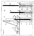
- FIG. 4 shows essentially the same terrain and device situation and the same sequence of processes as in FIG. The same details are provided with the same reference numerals. Reference is made to the description of FIG. 3 in this respect.
- a rigid cladding tube here is a less visible geotextile below open geotextile 27 'pulled over the central portion of the vibrator 17 and taken down so far that it penetrates the non-sustainable bottom layer 12 and protrudes with the lower end in the at least supportable bottom layer 13.
- the column foot 19 is already completed in the area of the load-bearing bottom layer 14.
- the lower column section 20 which here consists of the same material as the pedestal 19, is produced, which is radially supported directly in the lower bottom layer 13.
- an upper column section 28 which builds up on the lower column section 20 is formed by filling in the geotextile tube 27 'again with the same material.
- the radial supporting forces for the filling material are generated as a result of a radial widening of the sheath tube 27 '.
- the common principle takes place to cheapen and reduce the material consumption an additional envelope for the column material only in the area not at least supportive upper soil layers. This reduces the need for supporting bodies by length meters as well as the consumption of filling material in the area of non-sustainable layers.
- the load transfer takes place over the entire column body in the lower soil layers inside, where in the region of the lower column section load transfer on skin friction in addition to the support load of the column foot or as an exclusive force into the ground is possible.
Claims (17)
- Procédé de fabrication de colonnes dans des sols comprenant au moins une couche de sol non résistante à l'écrasement afin d'améliorer et/ou de stabiliser le sol de fondation, comprenant les étapes de procédé suivantes destinées à fabriquer une des colonnes,
un appareil déplaceur (17), notamment un vibroflotteur doté d'un tube d'égout ou un tube déplaceur doté d'une fermeture, est amené à vibrer depuis la surface du sol (11) à travers la au moins une couche de sol non résistante à l'écrasement jusque dans une couche de sol (13, 14) résistante à l'écrasement ou au moins apte au soutènement,
un tronçon de colonne inférieur (20) soutenu directement par une couche de sol (13, 14) au moins apte au soutènement, est établi à partir du matériau roulant de bas en haut, en particulier au moyen de l'appareil déplaceur (17),
une enveloppe tubulaire ou en forme de tuyau (22, 27) est encastrée depuis la surface de sol (11), en traversant au moins une couche de sol (12) inapte au soutènement, en parvenant jusqu'à l'intérieur du tronçon de colonne inférieur (20), l'enveloppe (22, 27) est remplie de matériau roulant pour former un tronçon de colonne supérieur (26, 28) soutenu par l'enveloppe. - Procédé selon la revendication 1,
caractérisé en ce que
un pied de colonne (19) concrété composé de matériau roulant est tout d'abord encastré, notamment au moyen de l'appareil déplaceur (17), dans la couche de sol (13, 14) résistante à l'écrasement ou au moins apte au soutènement, pied sur lequel le tronçon de colonne inférieur (20) est alors bâti. - Procédé selon l'une quelconque des revendications 1 ou 2,
caractérisé en ce que
l'enveloppe (22, 27), après une première vibration et une traction de l'appareil déplaceur (17) - après la fabrication du tronçon de colonne inférieur - est fixée sur l'extrémité inférieure de celui-ci et à l'occasion d'une seconde vibration de l'appareil déplaceur (17), est forée à sa profondeur conventionnelle. - Procédé selon l'une quelconque des revendications 1 ou 2,
caractérisé en ce que
l'enveloppe (22, 27) est fixée à distance de l'extrémité inférieure de
l'appareil déplaceur (17) de manière coaxiale sur celui-ci et à l'occasion d'une première vibration de l'appareil déplaceur (17) - avant la fabrication du tronçon de colonne inférieur - est forée et à la traction, se sépare de celui-ci ou est séparée de celui-ci. - Procédé selon l'une quelconque des revendications 1 à 4,
caractérisé en ce que
on utilise un matériau roulant exempt de liant - pierre, cailloutis, gravier, sable. - Procédé selon l'une quelconque des revendications 1 à 4,
caractérisé en ce que
on utilise un matériau roulant contenant un liant - mortier, béton. - Procédé selon l'une quelconque des revendications 1 à 6.
caractérisé en ce que
un corps tubulaire (22) - sans perforations, avec perforations; en tôle d'acier, en matériau composite, en matière plastique - est utilisé comme enveloppe. - Procédé selon l'une quelconque des revendications 1 à 7,
caractérisé en ce que
un tuyau géotextile (27) - contenant un composite de non tissé ; sans composite de non tissé - est utilisé comme enveloppe. - Procédé selon l'une quelconque des revendications 7 ou 8,
caractérisé en ce que
on utilise une enveloppe (22, 27) fermée par le dessous. - Corps de colonne dans le sol pour améliorer et/ou stabiliser des sols fabriqué selon un procédé selon l'une quelconque des revendications 1 à 9, comprenant au moins une couche de sol non résistante à l'écrasement, comportant
un tronçon de colonne inférieur (20) non tubé, qui est encastré dans des couches de sol (13, 14) résistantes à l'écrasement et/ou au moins aptes au soutènement dans le sens radial,
un tronçon de colonne supérieur (26, 28) doté d'une enveloppe (22, 27), lequel tronçon traverse au moins une couche de sol inapte au soutènement (12) et qui parvient avec son enveloppe (22, 27) dans le tronçon de colonne inférieur (20). - Corps de colonne selon la revendication 10,
caractérisé par
un pied de colonne (19) encastré dans une couche de sol (13, 14) résistante à l'écrasement ou au moins apte au soutènement, pied sur lequel est bâti le tronçon de colonne inférieur (20). - Corps de colonne selon l'une quelconque des revendications 10 ou 11,
caractérisé en ce que
on utilise un matériau roulant exempt de liant - pierre, cailloutis, gravier, sable. - Corps de colonne selon l'une quelconque des revendications 10 ou 11,
caractérisé en ce que
on utilise un matériau roulant contenant un liant -mortier, béton. - Corps de colonne selon l'une quelconque des revendications 10 à 13,
caractérisé en ce que
un corps tubulaire (22) - sans perforations, avec perforations ; en tôle d'acier, en matériau composite, en matière plastique - est utilisé comme enveloppe. - Corps de colonne selon l'une quelconque des revendications 10 à 13,
caractérisé en ce que
un tuyau géotextile (27) - rempli de non tissé, ne contenant pas de non tissé - est utilisé comme enveloppe. - Corps de colonne selon l'une quelconque des revendications 10 à 15,
caractérisé en ce que
on utilise une enveloppe (22, 27) fermée par le bas. - Sol de fondation amélioré et/ou stabilisé, dans lequel des corps de colonne selon l'une quelconque des revendications 10 à 16 sont encastrés en étant répartis selon une grille superficielle.
Applications Claiming Priority (2)
| Application Number | Priority Date | Filing Date | Title |
|---|---|---|---|
| DE10108602A DE10108602A1 (de) | 2001-02-22 | 2001-02-22 | Verfahren zum Herstellen von Säulen |
| DE10108602 | 2001-02-22 |
Publications (3)
| Publication Number | Publication Date |
|---|---|
| EP1234916A2 EP1234916A2 (fr) | 2002-08-28 |
| EP1234916A3 EP1234916A3 (fr) | 2002-12-18 |
| EP1234916B1 true EP1234916B1 (fr) | 2006-05-24 |
Family
ID=7675158
Family Applications (1)
| Application Number | Title | Priority Date | Filing Date |
|---|---|---|---|
| EP02003803A Expired - Lifetime EP1234916B1 (fr) | 2001-02-22 | 2002-02-20 | Méthode pour construire des colonnes |
Country Status (3)
| Country | Link |
|---|---|
| EP (1) | EP1234916B1 (fr) |
| AT (1) | ATE327389T1 (fr) |
| DE (2) | DE10108602A1 (fr) |
Cited By (1)
| Publication number | Priority date | Publication date | Assignee | Title |
|---|---|---|---|---|
| US8079780B2 (en) | 2005-05-20 | 2011-12-20 | Geopier Foundation Company, Inc. | Slotted mandrel for lateral displacement pier and method of use |
Families Citing this family (20)
| Publication number | Priority date | Publication date | Assignee | Title |
|---|---|---|---|---|
| US8152415B2 (en) | 2000-06-15 | 2012-04-10 | Geopier Foundation Company, Inc. | Method and apparatus for building support piers from one or more successive lifts formed in a soil matrix |
| DE20120859U1 (de) * | 2001-12-27 | 2003-05-08 | Kirchner Martin E | Vorrichtung zur Herstellung von textilummantelten Schüttbaustoffsäulen im Erdreich |
| DE10218330A1 (de) * | 2002-04-24 | 2003-11-13 | Vibroflotation B V | Verfahren und Vorrichtung zur Herstellung von Materialsäulen im Boden |
| DE10242264B4 (de) * | 2002-09-12 | 2005-02-24 | Josef Möbius Bau-Gesellschaft (GmbH & Co.) | Verfahren zur Herstellung eines interaktiven Tragsystems aus geotextilummantelten Sandsäulen und den anstehenden Böden zur Abtragung von Bauwerks- und Verkehrslasten bei wenig tragfähigem Untergrund |
| DE10310727B4 (de) * | 2003-03-12 | 2007-09-13 | Bauer Spezialtiefbau Gmbh | Füllrohr |
| DE10333613B4 (de) * | 2003-07-24 | 2011-06-30 | Keller Grundbau GmbH, 63067 | Verbesserung einer Weichschicht |
| DE102005001227A1 (de) | 2005-01-10 | 2006-07-20 | Keller Grundbau Gmbh | Baugrundverbesserung durch Hybrid- Säulen |
| US7488139B2 (en) | 2005-09-29 | 2009-02-10 | Geopier Foundation Company, Inc. | Pyramidal or conical shaped tamper heads and method of use for making rammed aggregate piers |
| DE102006033957B4 (de) * | 2006-07-22 | 2010-04-15 | Josef Möbius Bau-Aktiengesellschaft | Verfahren zur Erstellung von geotextilummantelten Säulen aus körnigem bzw. rolligem Material |
| US8562258B2 (en) | 2008-07-29 | 2013-10-22 | Geopier Foundation Company, Inc. | Shielded tamper and method of use for making aggregate columns |
| EP2313562B1 (fr) | 2008-07-29 | 2012-06-27 | Geopier Foundation Company, Inc. | Dispositif de damage equipe d'une protection et procede d'utilisation pour construire des colonnes de granulats |
| WO2011001297A1 (fr) * | 2009-06-30 | 2011-01-06 | Russet Trading & Investment 24 (Pty) Ltd | Procédé pour construire une colonne |
| US8221033B2 (en) * | 2009-09-12 | 2012-07-17 | Geopier Foundation Company, Inc. | Extensible shells and related methods for constructing a support pier |
| DE102010001839A1 (de) * | 2010-02-09 | 2011-08-11 | Alexander Degen | Rüttlervorrichtung mit einer Hubeinheit und Verfahren zur Herstellung von Materialsäulen |
| US9567723B2 (en) | 2010-09-13 | 2017-02-14 | Geopier Foundation Company, Inc. | Open-end extensible shells and related methods for constructing a support pier |
| CN102444119A (zh) * | 2011-09-19 | 2012-05-09 | 刘清洁 | 在卵石层、园砾层、砂层中施工沉管灌注桩的方法 |
| GB201209058D0 (en) * | 2012-05-23 | 2012-07-04 | Scotrenewables Tidal Power Ltd | Method of forming a concrete anchor device |
| EP3118375B1 (fr) | 2015-07-13 | 2018-04-11 | Dura Vermeer Beton & Waterbouw B.V. | Procédé pour améliorer la stabilité interne d'une berge |
| US10858796B2 (en) | 2015-07-27 | 2020-12-08 | Geopier Foundation Company, Inc. | Extensible shells and related methods for constructing a ductile support pier |
| CN111851479B (zh) * | 2020-07-30 | 2022-03-11 | 陕西龙海新创基础工程有限公司 | 一种在砂层或碎石层中施工沉管夯扩灌注桩的方法 |
Family Cites Families (7)
| Publication number | Priority date | Publication date | Assignee | Title |
|---|---|---|---|---|
| DE537358C (de) * | 1931-11-02 | Emil Gerbracht | Gruendungsverfahren in wenig tragfaehigem Boden unter Anwendung von Betonpfaehlen | |
| GB515120A (en) * | 1938-05-24 | 1939-11-27 | Alfred Hiley | Improved method of and means for forming concrete piles |
| AT296168B (de) * | 1968-11-05 | 1972-02-10 | Ignaz Dipl Ing Zeissl | Verfahren zur Herstellung eines abschnittsweise hergestellten Ortbetonpfahles mittels eines Dieselrammbären und eines Rammrohres |
| SE506023C2 (sv) * | 1992-10-09 | 1997-11-03 | Anders Mohss | Fristående vertikal gjutform för exempelvis plintar och pelare |
| DE4408173C5 (de) * | 1994-03-10 | 2006-04-27 | Josef Möbius Bau-Gesellschaft (GmbH & Co.) | Verfahren zur Stabilisierung des Untergrundes und zur Abtragung von Bauwerks- und Verkehrslasten |
| DE29611427U1 (de) * | 1996-07-01 | 1996-09-05 | Moebius Josef Bau | Rohrförmiger Verdrängungskörper |
| EP0900883B1 (fr) | 1997-09-04 | 2002-03-20 | JOSEF MÖBIUS BAUGESELLSCHAFT (GmbH & Co.) | Procédé pour former une colonne dans le sol, pour supporter le poids d'une structure ou de la circulation |
-
2001
- 2001-02-22 DE DE10108602A patent/DE10108602A1/de not_active Withdrawn
-
2002
- 2002-02-20 AT AT02003803T patent/ATE327389T1/de active
- 2002-02-20 EP EP02003803A patent/EP1234916B1/fr not_active Expired - Lifetime
- 2002-02-20 DE DE50206850T patent/DE50206850D1/de not_active Expired - Lifetime
Cited By (1)
| Publication number | Priority date | Publication date | Assignee | Title |
|---|---|---|---|---|
| US8079780B2 (en) | 2005-05-20 | 2011-12-20 | Geopier Foundation Company, Inc. | Slotted mandrel for lateral displacement pier and method of use |
Also Published As
| Publication number | Publication date |
|---|---|
| EP1234916A3 (fr) | 2002-12-18 |
| EP1234916A2 (fr) | 2002-08-28 |
| DE50206850D1 (de) | 2006-06-29 |
| ATE327389T1 (de) | 2006-06-15 |
| DE10108602A1 (de) | 2002-09-12 |
Similar Documents
| Publication | Publication Date | Title |
|---|---|---|
| EP1234916B1 (fr) | Méthode pour construire des colonnes | |
| DE2651023C2 (de) | Verfahren zum Herstellen eines Ortbetonpfahles mit einer Fußerweiterung und Vorrichtung zum Durchführen des Verfahrens | |
| EP1688543B1 (fr) | Amélioration de la consolidation du sol par des colonnes hybrides | |
| DE102018123794B3 (de) | Verfahren zur Herstellung eines spitzendruckfreien Bauelementes | |
| DE3445965A1 (de) | Verdichtende tiefgruendung, verfahren und vorrichtung zu deren herstellen | |
| EP1009884B1 (fr) | Procede et enveloppe pour produire une colonne de terre servant a supporter des charges d'ouvrage et des charges mobiles | |
| DE4408173C2 (de) | Verfahren zur Stabilisierung des Untergrundes und zur Abtragung von Bauwerks- und Verkehrslasten | |
| DE19518830B4 (de) | Verfahren zur Stabilisierung des Untergrundes und zur Abtragung von Bauwerks- und Verkehrslasten | |
| EP1134319A2 (fr) | Procédé et dispositif pour l'obtention d'un pieu en béton coulé in situ | |
| DE4224042A1 (de) | Verfahren und Vorrichtung zur Pfahlgründung | |
| EP0788572B1 (fr) | Procede de reprise en sous-oeuvre de batiments | |
| DE19941302A1 (de) | Vorrichtung und Verfahren zur Herstellung von im Boden versenkten Tragsäulen | |
| DE10025966C2 (de) | Stützschlauch-Säulen | |
| DE2639792A1 (de) | Verfahren zur oertlichen erhoehung der tragfaehigkeit von lockerem boden | |
| DE10242264B4 (de) | Verfahren zur Herstellung eines interaktiven Tragsystems aus geotextilummantelten Sandsäulen und den anstehenden Böden zur Abtragung von Bauwerks- und Verkehrslasten bei wenig tragfähigem Untergrund | |
| EP1273713B1 (fr) | Méthode pour construire des colonnes de matériaux pour améliorer la consolidation du sol | |
| DE102021116487B3 (de) | Geotextilummantelte Flüssigbodensäulen | |
| DE3324509A1 (de) | Verfahren zur herstellung von bohrpfaehlen mit verbesserter tragfaehigkeit | |
| EP3789469B1 (fr) | Procédé de fabrication d'un composant de base | |
| EP0340599B1 (fr) | Dalle de fond ajustable pour hauts bâtiments ainsi que méthode pour sa réalisation | |
| EP2706148B1 (fr) | Procédé d'amélioration de la portance de profilés ouverts disposés dans le sol de fondation et système réalisé grâce à ce procédé | |
| DE2521712A1 (de) | Verfahren zur fertigung von ortpfaehlen mit verbreiterungen im unteren teil | |
| EP3656926B1 (fr) | Procédé de stabilisation et d'élévation des bâtiments | |
| DE2851619A1 (de) | Verfahren zum herstellen eines ortbetonpfahles | |
| DE102020131395A1 (de) | Verfahren zum Sichern eines Bauwerks und Anordnung eines Bauwerks in einem Gelände |
Legal Events
| Date | Code | Title | Description |
|---|---|---|---|
| PUAI | Public reference made under article 153(3) epc to a published international application that has entered the european phase |
Free format text: ORIGINAL CODE: 0009012 |
|
| AK | Designated contracting states |
Kind code of ref document: A2 Designated state(s): AT BE CH CY DE DK ES FI FR GB GR IE IT LI LU MC NL PT SE TR |
|
| AX | Request for extension of the european patent |
Free format text: AL;LT;LV;MK;RO;SI |
|
| RIN1 | Information on inventor provided before grant (corrected) |
Inventor name: TRUNK, ULRICH, DR. Inventor name: VOELZKE, BURKHARD Inventor name: ASCHENBRENNER, GABRIELE Inventor name: ZIMMERMANN, KAI-UWE |
|
| PUAL | Search report despatched |
Free format text: ORIGINAL CODE: 0009013 |
|
| AK | Designated contracting states |
Kind code of ref document: A3 Designated state(s): AT BE CH CY DE DK ES FI FR GB GR IE IT LI LU MC NL PT SE TR |
|
| AX | Request for extension of the european patent |
Free format text: AL;LT;LV;MK;RO;SI |
|
| RIC1 | Information provided on ipc code assigned before grant |
Free format text: 7E 02D 3/08 A, 7E 02D 5/38 B, 7E 02D 5/44 B, 7E 02D 5/48 B, 7E 02D 5/66 B |
|
| 17P | Request for examination filed |
Effective date: 20030215 |
|
| AKX | Designation fees paid |
Designated state(s): AT BE CH CY DE DK ES FI FR GB GR IE IT LI LU MC NL PT SE TR |
|
| AXX | Extension fees paid |
Extension state: SI Payment date: 20030312 |
|
| GRAP | Despatch of communication of intention to grant a patent |
Free format text: ORIGINAL CODE: EPIDOSNIGR1 |
|
| GRAS | Grant fee paid |
Free format text: ORIGINAL CODE: EPIDOSNIGR3 |
|
| GRAA | (expected) grant |
Free format text: ORIGINAL CODE: 0009210 |
|
| AK | Designated contracting states |
Kind code of ref document: B1 Designated state(s): AT BE CH CY DE DK ES FI FR GB GR IE IT LI LU MC NL PT SE TR |
|
| AX | Request for extension of the european patent |
Extension state: SI |
|
| PG25 | Lapsed in a contracting state [announced via postgrant information from national office to epo] |
Ref country code: IT Free format text: LAPSE BECAUSE OF FAILURE TO SUBMIT A TRANSLATION OF THE DESCRIPTION OR TO PAY THE FEE WITHIN THE PRESCRIBED TIME-LIMIT;WARNING: LAPSES OF ITALIAN PATENTS WITH EFFECTIVE DATE BEFORE 2007 MAY HAVE OCCURRED AT ANY TIME BEFORE 2007. THE CORRECT EFFECTIVE DATE MAY BE DIFFERENT FROM THE ONE RECORDED. Effective date: 20060524 Ref country code: IE Free format text: LAPSE BECAUSE OF FAILURE TO SUBMIT A TRANSLATION OF THE DESCRIPTION OR TO PAY THE FEE WITHIN THE PRESCRIBED TIME-LIMIT Effective date: 20060524 Ref country code: GB Free format text: LAPSE BECAUSE OF FAILURE TO SUBMIT A TRANSLATION OF THE DESCRIPTION OR TO PAY THE FEE WITHIN THE PRESCRIBED TIME-LIMIT Effective date: 20060524 Ref country code: FI Free format text: LAPSE BECAUSE OF FAILURE TO SUBMIT A TRANSLATION OF THE DESCRIPTION OR TO PAY THE FEE WITHIN THE PRESCRIBED TIME-LIMIT Effective date: 20060524 |
|
| REG | Reference to a national code |
Ref country code: GB Ref legal event code: FG4D Free format text: NOT ENGLISH |
|
| REG | Reference to a national code |
Ref country code: CH Ref legal event code: EP |
|
| REG | Reference to a national code |
Ref country code: IE Ref legal event code: FG4D Free format text: LANGUAGE OF EP DOCUMENT: GERMAN |
|
| REF | Corresponds to: |
Ref document number: 50206850 Country of ref document: DE Date of ref document: 20060629 Kind code of ref document: P |
|
| REG | Reference to a national code |
Ref country code: CH Ref legal event code: NV Representative=s name: PA ALDO ROEMPLER |
|
| PG25 | Lapsed in a contracting state [announced via postgrant information from national office to epo] |
Ref country code: SE Free format text: LAPSE BECAUSE OF FAILURE TO SUBMIT A TRANSLATION OF THE DESCRIPTION OR TO PAY THE FEE WITHIN THE PRESCRIBED TIME-LIMIT Effective date: 20060824 Ref country code: DK Free format text: LAPSE BECAUSE OF FAILURE TO SUBMIT A TRANSLATION OF THE DESCRIPTION OR TO PAY THE FEE WITHIN THE PRESCRIBED TIME-LIMIT Effective date: 20060824 |
|
| PG25 | Lapsed in a contracting state [announced via postgrant information from national office to epo] |
Ref country code: ES Free format text: LAPSE BECAUSE OF FAILURE TO SUBMIT A TRANSLATION OF THE DESCRIPTION OR TO PAY THE FEE WITHIN THE PRESCRIBED TIME-LIMIT Effective date: 20060904 |
|
| PG25 | Lapsed in a contracting state [announced via postgrant information from national office to epo] |
Ref country code: PT Free format text: LAPSE BECAUSE OF FAILURE TO SUBMIT A TRANSLATION OF THE DESCRIPTION OR TO PAY THE FEE WITHIN THE PRESCRIBED TIME-LIMIT Effective date: 20061024 |
|
| GBV | Gb: ep patent (uk) treated as always having been void in accordance with gb section 77(7)/1977 [no translation filed] |
Effective date: 20060524 |
|
| REG | Reference to a national code |
Ref country code: IE Ref legal event code: FD4D |
|
| PG25 | Lapsed in a contracting state [announced via postgrant information from national office to epo] |
Ref country code: MC Free format text: LAPSE BECAUSE OF NON-PAYMENT OF DUE FEES Effective date: 20070228 |
|
| PLBE | No opposition filed within time limit |
Free format text: ORIGINAL CODE: 0009261 |
|
| STAA | Information on the status of an ep patent application or granted ep patent |
Free format text: STATUS: NO OPPOSITION FILED WITHIN TIME LIMIT |
|
| 26N | No opposition filed |
Effective date: 20070227 |
|
| EN | Fr: translation not filed | ||
| BERE | Be: lapsed |
Owner name: KELLER GRUNDBAU G.M.B.H. Effective date: 20070228 |
|
| PG25 | Lapsed in a contracting state [announced via postgrant information from national office to epo] |
Ref country code: BE Free format text: LAPSE BECAUSE OF NON-PAYMENT OF DUE FEES Effective date: 20070228 |
|
| PG25 | Lapsed in a contracting state [announced via postgrant information from national office to epo] |
Ref country code: GR Free format text: LAPSE BECAUSE OF FAILURE TO SUBMIT A TRANSLATION OF THE DESCRIPTION OR TO PAY THE FEE WITHIN THE PRESCRIBED TIME-LIMIT Effective date: 20060825 Ref country code: FR Free format text: LAPSE BECAUSE OF FAILURE TO SUBMIT A TRANSLATION OF THE DESCRIPTION OR TO PAY THE FEE WITHIN THE PRESCRIBED TIME-LIMIT Effective date: 20070309 |
|
| REG | Reference to a national code |
Ref country code: CH Ref legal event code: PCAR Free format text: ALDO ROEMPLER PATENTANWALT;BRENDENWEG 11 POSTFACH 154;9424 RHEINECK (CH) |
|
| PG25 | Lapsed in a contracting state [announced via postgrant information from national office to epo] |
Ref country code: FR Free format text: LAPSE BECAUSE OF FAILURE TO SUBMIT A TRANSLATION OF THE DESCRIPTION OR TO PAY THE FEE WITHIN THE PRESCRIBED TIME-LIMIT Effective date: 20060524 |
|
| PG25 | Lapsed in a contracting state [announced via postgrant information from national office to epo] |
Ref country code: LU Free format text: LAPSE BECAUSE OF NON-PAYMENT OF DUE FEES Effective date: 20070220 Ref country code: CY Free format text: LAPSE BECAUSE OF FAILURE TO SUBMIT A TRANSLATION OF THE DESCRIPTION OR TO PAY THE FEE WITHIN THE PRESCRIBED TIME-LIMIT Effective date: 20060524 |
|
| PG25 | Lapsed in a contracting state [announced via postgrant information from national office to epo] |
Ref country code: TR Free format text: LAPSE BECAUSE OF FAILURE TO SUBMIT A TRANSLATION OF THE DESCRIPTION OR TO PAY THE FEE WITHIN THE PRESCRIBED TIME-LIMIT Effective date: 20060524 |
|
| REG | Reference to a national code |
Ref country code: DE Ref legal event code: R084 Ref document number: 50206850 Country of ref document: DE |
|
| PGFP | Annual fee paid to national office [announced via postgrant information from national office to epo] |
Ref country code: NL Payment date: 20200220 Year of fee payment: 19 Ref country code: DE Payment date: 20200229 Year of fee payment: 19 Ref country code: AT Payment date: 20200218 Year of fee payment: 19 |
|
| PGFP | Annual fee paid to national office [announced via postgrant information from national office to epo] |
Ref country code: CH Payment date: 20200224 Year of fee payment: 19 |
|
| REG | Reference to a national code |
Ref country code: DE Ref legal event code: R119 Ref document number: 50206850 Country of ref document: DE |
|
| REG | Reference to a national code |
Ref country code: AT Ref legal event code: MM01 Ref document number: 327389 Country of ref document: AT Kind code of ref document: T Effective date: 20210220 |
|
| PG25 | Lapsed in a contracting state [announced via postgrant information from national office to epo] |
Ref country code: CH Free format text: LAPSE BECAUSE OF NON-PAYMENT OF DUE FEES Effective date: 20210228 Ref country code: AT Free format text: LAPSE BECAUSE OF NON-PAYMENT OF DUE FEES Effective date: 20210220 Ref country code: LI Free format text: LAPSE BECAUSE OF NON-PAYMENT OF DUE FEES Effective date: 20210228 |
|
| REG | Reference to a national code |
Ref country code: NL Ref legal event code: MM Effective date: 20210301 |
|
| PG25 | Lapsed in a contracting state [announced via postgrant information from national office to epo] |
Ref country code: NL Free format text: LAPSE BECAUSE OF NON-PAYMENT OF DUE FEES Effective date: 20210301 |
|
| PG25 | Lapsed in a contracting state [announced via postgrant information from national office to epo] |
Ref country code: DE Free format text: LAPSE BECAUSE OF NON-PAYMENT OF DUE FEES Effective date: 20210901 |