EP1234916B1 - Method for making column members - Google Patents
Method for making column members Download PDFInfo
- Publication number
- EP1234916B1 EP1234916B1 EP02003803A EP02003803A EP1234916B1 EP 1234916 B1 EP1234916 B1 EP 1234916B1 EP 02003803 A EP02003803 A EP 02003803A EP 02003803 A EP02003803 A EP 02003803A EP 1234916 B1 EP1234916 B1 EP 1234916B1
- Authority
- EP
- European Patent Office
- Prior art keywords
- envelope
- soil
- column
- process according
- column portion
- Prior art date
- Legal status (The legal status is an assumption and is not a legal conclusion. Google has not performed a legal analysis and makes no representation as to the accuracy of the status listed.)
- Expired - Lifetime
Links
Images

Classifications
-
- E—FIXED CONSTRUCTIONS
- E02—HYDRAULIC ENGINEERING; FOUNDATIONS; SOIL SHIFTING
- E02D—FOUNDATIONS; EXCAVATIONS; EMBANKMENTS; UNDERGROUND OR UNDERWATER STRUCTURES
- E02D3/00—Improving or preserving soil or rock, e.g. preserving permafrost soil
- E02D3/12—Consolidating by placing solidifying or pore-filling substances in the soil
- E02D3/123—Consolidating by placing solidifying or pore-filling substances in the soil and compacting the soil
-
- E—FIXED CONSTRUCTIONS
- E02—HYDRAULIC ENGINEERING; FOUNDATIONS; SOIL SHIFTING
- E02D—FOUNDATIONS; EXCAVATIONS; EMBANKMENTS; UNDERGROUND OR UNDERWATER STRUCTURES
- E02D3/00—Improving or preserving soil or rock, e.g. preserving permafrost soil
- E02D3/02—Improving by compacting
- E02D3/08—Improving by compacting by inserting stones or lost bodies, e.g. compaction piles
-
- E—FIXED CONSTRUCTIONS
- E02—HYDRAULIC ENGINEERING; FOUNDATIONS; SOIL SHIFTING
- E02D—FOUNDATIONS; EXCAVATIONS; EMBANKMENTS; UNDERGROUND OR UNDERWATER STRUCTURES
- E02D7/00—Methods or apparatus for placing sheet pile bulkheads, piles, mouldpipes, or other moulds
- E02D7/02—Placing by driving
- E02D7/06—Power-driven drivers
- E02D7/14—Components for drivers inasmuch as not specially for a specific driver construction
Definitions
- the invention relates to a method for producing columns in soils with at least one non-load-bearing bottom layer for the purpose of ground improvement or stabilization.
- methods There are a variety of methods are known, according to which insufficiently sustainable ground is improved by the incorporation of columns arranged in a grid.
- Insufficiently sustainable ground is improved by the incorporation of columns arranged in a grid.
- different mechanisms of action to advantage On the one hand can be done by deep-reaching columnar body load transfer into deeper-lying viable layers;
- a soil compaction between the column bodies can take place;
- soil water can be extracted from cohesive soils.
- the invention has for its object to propose a method for the production of columns, which leads to time-consuming and cost advantages in the application of low-lying viable or at least supportive layers and non-sustainable surface layers or intermediate layers.
- the solution to this problem consists in a method for producing columns in soils with at least one non-load-bearing bottom layer for the purpose of ground improvement or stabilization, with the following method steps for producing one of the columns, a displacement device, in particular a deep vibrator with lock tube or a displacement tube with closure, is vibrated from the bottom surface through the at least one non-viable bottom layer into a viable or at least sustainable soil layer, a directly supported by an at least supportable bottom layers lower column section, in particular by means of the displacement device, from bottom to top of rolling material constructed, a tubular or tubular casing is from the bottom surface, at least one non-sustainable bottom layer passing through, built into the lower column section extends in sufficient depth, the envelope is Kurs Schmu ng of an upper supported by the sheath Column section filled with rolling material.
- a thickened column foot of rolligem material in particular by means of the displacement device, first installed in the load-bearing soil layer on which then the lower column section is constructed.
- the main advantage of the method is therefore to use as far as possible in conventional stuffing or vibrating produced uncased column body, which can rest on a particular embedded in a stable or at least supportive layer thickened column base, and the stability of the column body by using a sheath exclusively to a depth from which there is sufficient continuous support capability down to the lower end of the column.
- the present stratification is to be determined by previous excavation drilling or other foundation exploration methods.
- the columns according to the invention are characterized even with the use of binder-free material even with the expected loads thereby dimensionally stable, that the envelope in the unstable floor area is designed so that it absorbs the expected stress conditions with minimal radial deformation and thus the loads in the un-threatened lower column section and the pedestal can be registered without damage.
- the envelope After a first process implementation, the envelope after a first shaking and pulling the displacer - after production of the lower column section - at the coaxially mounted on the lower end of this and drilled at a second shaking the displacement device to its intended depth.
- the process sequence is in this case initially the same as in the production of conventional vibrating or Stopf yarnen, which as already mentioned, when pulling the lower column section is made only zoom up to a first soft layer and the displacement device is then pulled to leave a displacement hole. In this case, the introduction of support liquid may be required.
- the envelope is mounted on the displacement device and drawn in a second additional shaking with this in the existing open Rüttelö réelle and partially introduced into the existing lower column section.
- the displacer can be drawn by immediately filling the casing and compacting the filler material (contractor method) or drawing it without introducing filler material, which can then be filled from the top end of the casing (from the bottom surface).
- the casing is mounted at a distance from the lower end of the displacer coaxially on this and already at a first shaking of the displacement device - made before the production of the lower column section - with this and separated while pulling from this.
- the latter separation can be done automatically, if in one direction effective entrainment means are used.
- special coupling means separable from the ground surface may be provided.
- the enclosure is brought to the intended depth, so that it extends down to at least sustainable soil layers.
- the material of the column can be introduced in a single operation from bottom to top be carried out, wherein in the upper region, the radial support is carried out by the already installed sheath. Accelerated pulling of the displacement device in the region of the enclosure and filling of filling material in the upper column section from the bottom surface is here less sensible, but not excluded.
- binderless, mobile material - rock, gravel, gravel, sand - is appropriate in those cases where the columns are also said to have vertical drainage, i. when water permeability in the vertical direction is to be guaranteed, or in which the same is not disadvantageous.
- binder-containing rolligem material - mortar, concrete - is preferable, especially when higher loads are to be removed and / or water exchange between different water-bearing layers is to be avoided.
- a geotextile tube be it with nonwoven composite portion or without fleece portion, can be used as the sheathing.
- the tube sheaths used are usually designed as open-bottom tube.
- the present invention finds application wherever the displacement or compaction of the soil during the introduction of stuffing or vibrating columns, the required support stress or reaction stress in upper soil layers - surface layers or intermediate layers - is not achieved and the soil for the functionality of the column required radial support can not build up or a horizontal running of the mortar or concrete during insertion before its hardening can not prevent.
- the column In the lying directly above the lower end of the column soil layers in which there is sufficient radial support throughout, the column is prepared according to known techniques without additional coating.
- a sufficiently load-bearing or at least supportable layer must be present, in which initially a pedestal can be stuffed out of roll-like material.
- a pedestal can be stuffed out of roll-like material.
- gravel, gravel, sand, mortar or concrete, d. H. case-hardened material with or without addition of binder is used.
- binder-containing material By using binder-containing material, a vertical flow can be reduced or prevented, so that a connection between different groundwater floors remains suppressed.
- the column is according to the invention with a covering made of tubes or geotextile tubes.
- the upper pillar portion (with wrapper) can be filled and stuffed with coarse material with or without binder additive, usually gravel, crushed stone, sand, mortar or concrete, regardless of the embodiment of the lower pillar portion (without wrapper).
- an envelope made of a material that undergoes significant elongation during load application, so in particular in a geotextile envelope, it is advantageous to compress the filler in the envelope immediately during column production, so that no significant additional strains occur during load application and only construction-compatible settlements are to be accepted later.
- the wrapper may additionally serve to prevent or substantially prevent a change or chemical reaction of the column material with the soil, the soil moisture, the groundwater, for example, to reduce or completely avoid a change in the pH in the surrounding soil by the introduction of binder.
- viable columns can be prepared, which can be charged immediately or after hardening of the binder optionally used. Due to their method of manufacture, only small settlements are expected when applying loads.
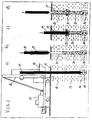
- FIG. 1 shows in four phases a) to d) the preparation of a column according to the invention.
- a vertically cut ground with the surface 11 has a non-load-bearing and unsupportable upper soil layer 12 (soft layer), including an at least supportable soil layer 13 and finally including a well-soil layer 14th
- a brought on the surface 11 in position caterpillar 15 is shown in the erected leader 16, a vibrator 17 is guided, which passes through a feed hopper 18 for material introduction.
- the Rüttlerspitze is shaken to the viable soil layer 14.
- Dashed lines show a thickened column foot 19, which can optionally be produced in a first step by vibratory compaction or stuffing compaction of a rolling material, with or without binder aggregate.
- the vibrator 17 is already fully drawn, wherein - on the optionally existing column foot 19 - in vibrating or stuffing a lower column section 20 is made of rolligem material that extends into the viable bottom layer 14 and radially directly from the bottom of supportive soil layer 13 is supported.
- This lower column section 20 protrudes slightly into the unsupportable upper bottom layer 12, while otherwise the displacement hole 21 can be seen in this bottom layer.
- a tube 22 is coaxial mounted, which has inner driver 24 at the lower end, which can be taken by driving pin 23 at the bottom of the vibrator.
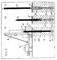
- the geotextile tube 27 is filled with rolling material to form an upper column section 28, whereby the tube 27 can build up supporting forces by radial expansion and delimits the filling material essentially against the pending floor.
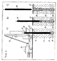
- FIG. 3 substantially the same device situation and the same bottom layering as in FIGS. 1 and 2 are shown in three phases. The same details are provided with the same reference numerals. On the local description reference is made in this regard.
- the corresponding entrainment means 23, 24 are in this case at a corresponding distance from the Rüttlerspitze.
- a thickened column foot 19 is shown with dashed lines, which may optionally be constructed in the load-bearing bottom layer 14.
- the wrapping tube 22 has already reached its intended position, which penetrates the non-sustainable bottom layer 12 and projects into the at least supportable bottom layer 13.
- the vibrator 17 is already retracted into the interior of the casing tube 22 ', after it has produced a lower column section 20 in the region of the at least supportable bottom layer 13, which is supported radially directly from the bottom.
- the vibrator 17 is completely pulled out of the casing tube 22 'upwards, wherein the casing tube 22' is filled with rolling material to form an upper column portion 28, which here differs from the material of the lower column portion 20.
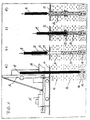
- FIG. 4 shows essentially the same terrain and device situation and the same sequence of processes as in FIG. The same details are provided with the same reference numerals. Reference is made to the description of FIG. 3 in this respect.
- a rigid cladding tube here is a less visible geotextile below open geotextile 27 'pulled over the central portion of the vibrator 17 and taken down so far that it penetrates the non-sustainable bottom layer 12 and protrudes with the lower end in the at least supportable bottom layer 13.
- the column foot 19 is already completed in the area of the load-bearing bottom layer 14.
- the lower column section 20 which here consists of the same material as the pedestal 19, is produced, which is radially supported directly in the lower bottom layer 13.
- an upper column section 28 which builds up on the lower column section 20 is formed by filling in the geotextile tube 27 'again with the same material.
- the radial supporting forces for the filling material are generated as a result of a radial widening of the sheath tube 27 '.
- the common principle takes place to cheapen and reduce the material consumption an additional envelope for the column material only in the area not at least supportive upper soil layers. This reduces the need for supporting bodies by length meters as well as the consumption of filling material in the area of non-sustainable layers.
- the load transfer takes place over the entire column body in the lower soil layers inside, where in the region of the lower column section load transfer on skin friction in addition to the support load of the column foot or as an exclusive force into the ground is possible.
Abstract
Description
Die Erfindung betrifft ein Verfahren zum Herstellen von Säulen in Böden mit zumindest einer nicht-tragfähigen Bodenschicht zum Zweck der Baugrundverbesserung bzw. -stabilisierung. Es sind vielfältige Verfahren bekannt, nach denen nicht ausreichend tragfähiger Untergrund durch das Einbauen von in einem Raster angeordneten Säulen verbessert wird. Hierbei kommen verschiedene Wirkmechanismen zur Geltung. Zum einen kann durch tiefreichende Säulenkörper eine Lastabtragung in tiefer liegende tragfähige Schichten erfolgen; daneben kann durch das Einbauen der Säulenkörper ohne vorherigen Bodenaushub eine Bodenverdichtung zwischen den Säulenkörpern erfolgen; schließlich kann bei Verwendung von trockenem Bindemittel in den Säulenkörpern Bodenwasser aus bindigen Böden entzogen werden.The invention relates to a method for producing columns in soils with at least one non-load-bearing bottom layer for the purpose of ground improvement or stabilization. There are a variety of methods are known, according to which insufficiently sustainable ground is improved by the incorporation of columns arranged in a grid. Here are different mechanisms of action to advantage. On the one hand can be done by deep-reaching columnar body load transfer into deeper-lying viable layers; In addition, by incorporating the columnar body without prior excavation, a soil compaction between the column bodies can take place; Finally, when using dry binder in the column bodies soil water can be extracted from cohesive soils.
Aus Kosten- und Verfahrensgründen günstig sind unverrohrte Säulen, die in Stopf- oder Rütteltechnik mittels Tiefenrüttlern mit Schleusenrohr in einem kontinuierlichen Arbeitsgang auf einem Säulenfuß aufgebaut werden können. Diese Herstelltechnik kommt an ihre Grenzen oder versagt beim Vorliegen von Weichschichten, die keine ausreichenden radialen Stützkräfte aufbauen können, um den Säulenkörper bei Belastung durch Auflasten formstabil halten zu können, in folgenden nicht-stützfähigen Bodenschichten genannt.For cost and procedural reasons are favorable uncased columns, which can be constructed in a continuous operation on a pedestal in stuffing or vibrating by means of deep vibrators with lock tube. This manufacturing technique comes to its limits or fails in the presence of soft layers that can not build sufficient radial support forces to hold the column body when loaded by loading dimensionally stable, called in the following non-sustainable soil layers.
Aus der DE 44 08 173 A1 und der EP 0 900 883 A1 ist es bekannt, Säulenkörper, die bis in eine tragfähige Bodenschicht hineinreichen, mit einer Umhüllung aus einem Rohr oder einem Geotextilmaterial zu versehen, wobei zunächst ein Aushub oder eine Verdrängung des Bodens erfolgt und dann Umhüllung und Füllmaterial eingebracht werden. Bei sehr tief liegenden tragfähigen Schichten ist das Verfahren, das eine zeitweilige Verrohrung erfordert, zu aufwendig.From DE 44 08 173 A1 and EP 0 900 883 A1 it is known to provide column bodies which extend into a load-bearing bottom layer, with an envelope made of a tube or a geotextile material, wherein first an excavation or a displacement of the soil takes place and then wrapping and filling material are introduced. For very low-lying, load-bearing layers, the process requiring temporary piping is too expensive.
Hiervon ausgehend, liegt der Erfindung die Aufgabe zugrunde, ein Verfahren zur Herstellung von Säulen vorzuschlagen, das bei tiefliegenden tragfähigen oder zumindest stützfähigen Schichten und nicht-stützfähigen Oberflächenschichten oder Zwischenschichten zu Zeit- und Kostenvorteilen bei der Anwendung führt. Die Lösung hierfür besteht in einem Verfahren zum Herstellen von Säulen in Böden mit zumindest einer nicht-tragfähigen Bodenschicht zum Zweck der Baugrundverbesserung bzw. -stabilisierung, mit den folgenden Verfahrensschritten zur Herstellung einer der Säulen, ein Verdrängungsgerät, insbesondere ein Tiefenrüttler mit Schleusenrohr oder ein Verdrängungsrohr mit Verschluß, wird von der Bodenoberfläche aus durch die zumindest eine nicht-tragfähige Bodenschicht bis in eine tragfähige oder zumindest stützfähige Bodenschicht eingerüttelt, ein unmittelbar von einer zumindest stützfähigen Bodenschichten abgestützter unterer Säulenabschnitt wird, insbesondere mittels des Verdrängungsgerätes, von unten nach oben aus rolligem Material aufgebaut, eine rohr- oder schlauchförmige Umhüllung wird von der Bodenoberfläche aus, zumindest eine nicht-stützfähige Bodenschicht durchsetzend, bis in den unteren Säulenabschnitt hineinreichend eingebaut, die Umhüllung wird zur Bildung eines von der Umhüllung gestützten oberen Säulenabschnitts mit rolligem Material verfüllt. Dieses wird in der Umhüllung verdichtet.On this basis, the invention has for its object to propose a method for the production of columns, which leads to time-consuming and cost advantages in the application of low-lying viable or at least supportive layers and non-sustainable surface layers or intermediate layers. The solution to this problem consists in a method for producing columns in soils with at least one non-load-bearing bottom layer for the purpose of ground improvement or stabilization, with the following method steps for producing one of the columns, a displacement device, in particular a deep vibrator with lock tube or a displacement tube with closure, is vibrated from the bottom surface through the at least one non-viable bottom layer into a viable or at least sustainable soil layer, a directly supported by an at least supportable bottom layers lower column section, in particular by means of the displacement device, from bottom to top of rolling material constructed, a tubular or tubular casing is from the bottom surface, at least one non-sustainable bottom layer passing through, built into the lower column section extends in sufficient depth, the envelope is zum Bildu ng of an upper supported by the sheath Column section filled with rolling material. This is compacted in the cladding.
In günstiger Weiterbildung, insbesondere bei Vorliegen von tragfähigen Bodenschichten, wird zunächst ein verdickter Säulenfuß aus rolligem Material, insbesondere mittels des Verdrängungsgerätes, in der tragfähigen Bodenschicht eingebaut, auf dem dann der untere Säulenabschnitt aufgebaut wird.In a favorable development, in particular in the presence of load-bearing soil layers, a thickened column foot of rolligem material, in particular by means of the displacement device, first installed in the load-bearing soil layer on which then the lower column section is constructed.
Der wesentliche Vorteil des Verfahrens besteht also darin, soweit eben möglich in herkömmlicher Stopf- oder Rütteltechnik hergestellte unverrohrte Säulenkörper zu verwenden, die insbesondere auf einem in einer tragfähigen oder zumindest stützfähigen Schicht eingebetteten verdickten Säulenfuß ruhen können, und die Stabilität des Säulenkörpers durch Einsatz einer Umhüllung ausschließlich bis in eine Tiefe, von der aus nach unten eine ausreichende durchgehende Stützfähigkeit bis zum unteren Säulenende vorliegt, herzustellen. Die vorliegende Schichtung ist durch vorhergehende Aufschlußbohrungen oder andere Baugrunderkundungsmethoden zu ermitteln.The main advantage of the method is therefore to use as far as possible in conventional stuffing or vibrating produced uncased column body, which can rest on a particular embedded in a stable or at least supportive layer thickened column base, and the stability of the column body by using a sheath exclusively to a depth from which there is sufficient continuous support capability down to the lower end of the column. The present stratification is to be determined by previous excavation drilling or other foundation exploration methods.
Die erfindungsgemäßen Säulen sind selbst bei Verwendung von ausschließlich bindemittelfreiem Material auch bei den zu erwartenden Auflasten dadurch formstabil, daß die Umhüllung im instabilen Bodenbereich so ausgelegt ist, daß sie die zu erwartenden Spannungszustände mit allenfalls geringer Radialverformung auffängt und damit die Lasten in den unverrohten unteren Säulenabschnitt und den Säulenfuß schadensfrei eingetragen werden können.The columns according to the invention are characterized even with the use of binder-free material even with the expected loads thereby dimensionally stable, that the envelope in the unstable floor area is designed so that it absorbs the expected stress conditions with minimal radial deformation and thus the loads in the un-threatened lower column section and the pedestal can be registered without damage.
Nach einer ersten Verfahrensdurchführung wird die Umhüllung nach einem ersten Einrütteln und Ziehen des Verdrängungsgerätes - nach Herstellung des unteren Säulenabschnitts - an dessen unterem Ende koaxial auf diesem befestigt und bei einem zweiten Einrütteln des Verdrängungsgerätes auf ihre bestimmungsgemäße Tiefe niedergebracht. Der Verfahrensablauf stellt sich hierbei zunächst genauso dar wie bei der Herstellung üblicher Rüttel- oder Stopfsäulen, wobei wie bereits erwähnt, beim Ziehen der untere Säulenabschnitt nur bis an eine erste Weichschicht heran hergestellt wird und das Verdrängungsgerät danach unter Offenlassen eines Verdrängungsloches gezogen wird. Hierbei kann das Einbringen von Stützflüssigkeit erforderlich werden. Danach wird die Umhüllung auf dem Verdrängungsgerät befestigt und in einem zweiten zusätzlichen Rüttelvorgang mit diesem in die vorhandene offene Rüttelöffnung eingezogen und teilweise in den bereits bestehenden unteren Säulenabschnitt eingebracht. Danach kann das Verdrängungsgerät unter sofortigem Auffüllen der Umhüllung und Verdichten des Füllmaterials (Kontraktorverfahren) gezogen werden oder ohne Einbringen von Füllmaterial gezogen werden, welches dann vom oberen Umhüllungsende (von der Bodenoberfläche aus) eingefüllt werden kann.After a first process implementation, the envelope after a first shaking and pulling the displacer - after production of the lower column section - at the coaxially mounted on the lower end of this and drilled at a second shaking the displacement device to its intended depth. The process sequence is in this case initially the same as in the production of conventional vibrating or Stopfsäulen, which as already mentioned, when pulling the lower column section is made only zoom up to a first soft layer and the displacement device is then pulled to leave a displacement hole. In this case, the introduction of support liquid may be required. Thereafter, the envelope is mounted on the displacement device and drawn in a second additional shaking with this in the existing open Rüttelöffnung and partially introduced into the existing lower column section. Thereafter, the displacer can be drawn by immediately filling the casing and compacting the filler material (contractor method) or drawing it without introducing filler material, which can then be filled from the top end of the casing (from the bottom surface).
Nach einer zweiten vereinfachten Verfahrensführung wird die Umhüllung mit Abstand vom unteren Ende des Verdrängungsgerätes koaxial auf diesem befestigt und bereits bei einem ersten Einrütteln des Verdrängungsgerätes - vor dem Herstellen des unteren Säulenabschnitts - mit diesem niedergebracht und beim Ziehen von diesem getrennt. Das letztgenannte Trennen kann selbsttätig erfolgen, wenn in nur einer Richtung wirksame Mitnehmermittel verwendet werden. Es können auch besondere Kopplungsmittel, die von der Bodenoberfläche aus trennbar sind, vorgesehen sein. Bei dieser Verfahrensführung wird die Umhüllung auf die bestimmungsgemäße Tiefe gebracht, so daß sie bis in zumindest stützfähigen Bodenschichten hinunterreicht. Beim Ziehen des Verdrängungsgerätes kann das Material der Säule in einem einheitlichen Vorgang von unten nach oben eingebracht werden, wobei im oberen Bereich die radiale Abstützung durch die bereits eingebaute Umhüllung erfolgt. Ein beschleunigtes Ziehen des Verdrängungsgerätes im Bereich der Umhüllung und ein Einfüllen von Füllmaterial in den oberen Säulenabschnitt von der Bodenoberfläche aus ist hierbei weniger sinnvoll, jedoch nicht ausgeschlossen.According to a second simplified procedure, the casing is mounted at a distance from the lower end of the displacer coaxially on this and already at a first shaking of the displacement device - made before the production of the lower column section - with this and separated while pulling from this. The latter separation can be done automatically, if in one direction effective entrainment means are used. Also, special coupling means separable from the ground surface may be provided. In this process, the enclosure is brought to the intended depth, so that it extends down to at least sustainable soil layers. When pulling the displacement device, the material of the column can be introduced in a single operation from bottom to top be carried out, wherein in the upper region, the radial support is carried out by the already installed sheath. Accelerated pulling of the displacement device in the region of the enclosure and filling of filling material in the upper column section from the bottom surface is here less sensible, but not excluded.
Die Verwendung von bindemittelfreiem rolligem Material - Gestein, Schotter, Kies, Sand - bietet sich in solchen Fällen an, in denen die Säulen auch vertikale Dränwirkung haben sollen, d.h. wenn Wasserdurchlässigkeit in vertikaler Richtung garantiert sein soll, oder in denen selbiges nicht von Nachteil ist.The use of binderless, mobile material - rock, gravel, gravel, sand - is appropriate in those cases where the columns are also said to have vertical drainage, i. when water permeability in the vertical direction is to be guaranteed, or in which the same is not disadvantageous.
In anderen Fällen ist die Verwendung von bindemittelhaltigem rolligem Material - Mörtel, Beton - vorzuziehen, insbesondere wenn höhere Auflasten abzutragen sind und/oder Wasseraustausch zwischen verschiedenen wasserführenden Schichten zu vermeiden ist.In other cases, the use of binder-containing rolligem material - mortar, concrete - is preferable, especially when higher loads are to be removed and / or water exchange between different water-bearing layers is to be avoided.
Als Umhüllung kommen im wesentlichen formstabile Rohrkörper, sei es ohne Durchbrüche, sei es mit Durchbrüchen, aus den bekannten Materialen wie Stahlblech, Verbundwerkstoff oder Kunststoff in Betracht. Nach einem anderen Ansatz kann als Umhüllung ein Geotextilschlauch, sei es mit Vliesverbundanteil oder ohne Vliesanteil zur Verwendung kommen. In diesem Fall stellt sich ein notwendiger radialer Spannungszustand im Säulenkörper erst als Folge einer deutlichen radialen Aufweitung des Schlauchkörpers ein. Die verwendeten Rohrumhüllungen werden in der Regel als unten offenes Rohr ausgeführt. Bei der Verwendung von Geotextilien kann die Verwendung unten geschlossener Schläuche zum erleichterten Niederbringen günstiger sein.When wrapping come substantially dimensionally stable tubular body, whether without breakthroughs, be it with breakthroughs, from the known materials such as steel, composite material or plastic into consideration. According to another approach, a geotextile tube, be it with nonwoven composite portion or without fleece portion, can be used as the sheathing. In this case, a necessary radial stress state in the column body arises only as a result of a significant radial expansion of the hose body. The tube sheaths used are usually designed as open-bottom tube. When using geotextiles, the use of closed-bottom hoses may be more convenient for easier downsizing.
Die vorliegende Erfindung findet überall dort Anwendung, wo bei der Verdrängung bzw. Verdichtung des Bodens beim Einbringen von Stopf- oder Rüttelsäulen die erforderliche Stützspannung bzw. Reaktionsspannung in oberen Bodenschichten - Oberflächenschichten oder Zwischenschichten - nicht erreicht wird und der Boden die für die Funktionstüchtigkeit der Säule erforderliche radiale Stützung nicht aufbauen kann bzw. ein horizontalles Verlaufen des Mörtels oder Betons beim Einbringen vor dessen Erhärtung nicht verhindern kann.The present invention finds application wherever the displacement or compaction of the soil during the introduction of stuffing or vibrating columns, the required support stress or reaction stress in upper soil layers - surface layers or intermediate layers - is not achieved and the soil for the functionality of the column required radial support can not build up or a horizontal running of the mortar or concrete during insertion before its hardening can not prevent.
In den unmittelbar über dem unteren Säulenende liegenden Bodenschichten, in denen durchgehend eine ausreichende radiale Stützung gegeben ist, wird die Säule entsprechend bekannten Techniken ohne zusätzliche Umhüllung hergestellt.In the lying directly above the lower end of the column soil layers in which there is sufficient radial support throughout, the column is prepared according to known techniques without additional coating.
Im Bereich der Lasteintragung über den unteren Säulenabschnitt muß eine ausreichend tragfähige oder zumindest stützfähige Schicht vorliegen, in der zunächst ein Säulenfuß aus rolligem Material ausgestopft werden kann. Üblicherweise werden Kies, Schotter, Sand, Mörtel oder Beton, d. h. anwendungsfallweise rolliges Material ohne oder mit Bindemittelzusatz vewendet.In the area of the load application over the lower column section, a sufficiently load-bearing or at least supportable layer must be present, in which initially a pedestal can be stuffed out of roll-like material. Usually gravel, gravel, sand, mortar or concrete, d. H. case-hardened material with or without addition of binder is used.
Durch Verwendung von bindemittelhaltigem Material kann eine vertikale Durchströmung reduziert oder verhindert werden, so daß eine Verbindung zwischen unterschiedlichen Grundwasserstockwerken unterbunden bleibt.By using binder-containing material, a vertical flow can be reduced or prevented, so that a connection between different groundwater floors remains suppressed.
In oberen Bodenschichten - Oberflächenschichten oder Zwischenschichten - , in denen eine ausreichende radiale Stützung der Säule nicht gewährleistet ist, wird die Säule erfindungsgemäß mit einer Umhüllung bestehend aus Rohren oder Geotextilschläuchen hergestellt.In upper soil layers - surface layers or intermediate layers - in which a sufficient radial support of the column is not guaranteed, the column is according to the invention with a covering made of tubes or geotextile tubes.
Der obere Säulenabschnitt (mit Umhüllung) kann unabhängig von der Ausführungsart des unteren Säulenabschnittes (ohne Umhüllung) mit rolligem Material ohne oder mit Bindemittelzusatz gefüllt und ausgestopft werden, üblicherweise mit Kies, Schotter, Sand , Mörtel oder Beton.The upper pillar portion (with wrapper) can be filled and stuffed with coarse material with or without binder additive, usually gravel, crushed stone, sand, mortar or concrete, regardless of the embodiment of the lower pillar portion (without wrapper).
Wird eine Umhüllung aus einem Material verwendet, das bei Lastaufbringung eine nennenswerte Dehnung erfährt, also insbesondere bei einer Umhüllung aus Geotextil, ist es vorteilhaft, das Füllmaterial in der Umhüllung sofort bei der Säulenherstellung zu verdichten, so daß keine erheblichen zusätzlichen Dehnungen bei Lastaufbringung erfolgen und nur bauwerksverträgliche Setzungen später hinzunehmen sind.If an envelope is used made of a material that undergoes significant elongation during load application, so in particular in a geotextile envelope, it is advantageous to compress the filler in the envelope immediately during column production, so that no significant additional strains occur during load application and only construction-compatible settlements are to be accepted later.
In Bodenschichten, in denen für unverrohrte Säulen, z. B. Schottersäulen, vermörtelte Stopfsäulen, Fertigmörtelstopfsäulen, Betonrüttelsäulen, erforderliche Stützspannungen nicht dauerhaft durch Verdrängung und Verdichtung des umgebenen Bodens erzeugt werden können, d. h. in denen der Boden nur in geringem Maße zur radialen Stützspannung beiträgt, muß diese daher zu einem wesentlichen Teil durch die Umfangsdehnung der Umhüllung beim Einbringen des Füllmaterials aufgebracht werden.In soil layers in which for uncased columns, z. B. Schottersäulen, mortared Stopfsäulen, Fertigmörtelstopfsäulen, Betonrüttelsäulen, required support voltages can not be permanently generated by displacement and compression of the surrounding soil, d. H. in which the soil contributes only slightly to the radial support stress, it must therefore be applied to a substantial extent by the circumferential expansion of the envelope during introduction of the filling material.
Die Umhüllung kann zusätzlich dazu dienen, einen Austausch oder chemische Reaktionen des Säulenmaterials mit dem Boden, der Bodenfeuchte, dem Grundwasser zu verhindern, beispielsweise eine Veränderung des pH-Wertes im umgebenden Boden durch das Einbringen von Bindemittel zu reduzieren oder gänzlich zu vermeiden.The wrapper may additionally serve to prevent or substantially prevent a change or chemical reaction of the column material with the soil, the soil moisture, the groundwater, for example, to reduce or completely avoid a change in the pH in the surrounding soil by the introduction of binder.
Mit dem erfindungsgemäßen Verfahren können tragfähige Säulen hergestellt werden, die sofort oder nach Erhärtung des gegebenenfalls verwendeten Bindemittels belastet werden können. Aufgrund ihrer Herstellungsweise sind nur geringe Setzungen bei einem Aufbringen von Lasten zu erwarten.With the method according to the invention viable columns can be prepared, which can be charged immediately or after hardening of the binder optionally used. Due to their method of manufacture, only small settlements are expected when applying loads.
Vor der Herstellung des zu verbessernden Baugrundes ist ein detaillierter Baugrundaufschluß erforderlich; insbesondere zur Festlegung der erforderlichen Länge der Umhüllungen werden vorzugsweise in einem engen Raster Drucksondierungen ausgeführt, mit denen der Übergang von nicht-stützfähigen Bodenschichten zu stütz- bzw. tragfähigen Bodenschichten ermittelt wird. Die untere Grenzschicht der untersten nicht-stützfähigen Bodenschicht bestimmt die Tiefe der Umhüllung, die stütz- und tragfähigen Bodenschichten brauchen im wesentlichen nicht unterschieden zu werden. Das Verfahren ist ohne weiteres anwendbar, wenn unter den nicht-stützfähigen Bodenschichten ausschließlich gut tragfähige Bodenschichten liegen. Es ist sinngemäß jedoch auch anwendbar, wenn unter den nicht-stützfähigen Bodenschichten ausschließlich zumindest stützfähige Bodenschichten liegen und die Säulen in diesem Bereich ausreichend tief sind, um einen Lastabtrag vorwiegend über Mantelreibung zu bewirken.
Figur 1- zeigt ein erstes, zweistufiges erfindungsgemäßes Verfahren zur Herstellung von Säulen unter Verwendung einer Rohrumhüllung;
- Figur 2
- zeigt ein zweites, zweistufiges erfindungsgemäßes verfahren unter Verwendung einer Geotextilumhüllung;
- Figur 3
- zeigt ein drittes, einstufiges erfindungsgemäßes Verfahren unter Verwendung einer Rohrumhüllung;
- Figur 4
- zeigt ein viertes, einstufiges erfindungsgemäßes Verfahrend unter Verwendung einer Geotextilumhüllung.
- FIG. 1
- shows a first, two-step process according to the invention for the production of columns using a pipe jacket;
- FIG. 2
- shows a second, two-stage process according to the invention using a geotextile sheath;
- FIG. 3
- shows a third, one-step process according to the invention using a pipe jacket;
- FIG. 4
- shows a fourth, one-step process according to the invention using a geotextile wrapper.
In Figur 1 ist in vier Phasen a) bis d) die Herstellung einer erfindungsgemäßen Säule dargestellt. Ein vertikal geschnittener Baugrund mit der Oberfläche 11 hat eine nicht-trag- und nicht-stützfähige obere Bodenschicht 12 (Weichschicht), darunter eine zumindest stützfähige Bodenschicht 13 und schließlich darunter eine gut tragfähige Bodenschicht 14.FIG. 1 shows in four phases a) to d) the preparation of a column according to the invention. A vertically cut ground with the
In der Darstellung a) ist ein auf der Oberfläche 11 in Stellung gebrachtes Raupenfahrzeug 15 gezeigt, in dessen aufgestelltem Mäkler 16 ein Rüttler 17 geführt ist, der einen Aufgabetrichter 18 zur Materialeinbringung durchfährt. Die Rüttlerspitze ist bis in die tragfähige Bodenschicht 14 eingerüttelt. Mit gestrichelten Linien ist ein verdickter Säulenfuß 19 gezeigt, der fakultativ in einem ersten Schritt durch Rüttelverdichtung oder Stopfverdichtung aus rolligem Material - mit oder ohne Bindemittelzuschlag - erzeugt werden kann.In the representation a) a brought on the
In der Darstellung b) ist der Rüttler 17 bereits vollständig gezogen, wobei - auf dem fakultativ vorhandenen Säulenfuß 19 - in Rütteltechnik oder Stopftechnik ein unterer Säulenabschnitt 20 aus rolligem Material aufgebaut ist, der bis in die tragfähige Bodenschicht 14 reicht und radial unmittelbar vom Boden der stützfähigen Bodenschicht 13 abgestützt wird. Dieser untere Säulenabschnitt 20 ragt bis in die nicht-stützfähige obere Bodenschicht 12 geringfügig hinein, während im übrigen das Verdrängungsloch 21 in dieser Bodenschicht zu erkennen ist. Auf das untere Ende des Rüttlers 17 ist ein Rohr 22 koaxial aufgezogen, das über innere Mitnehmer 24 am unteren Ende verfügt, die von Mitnehmerzapfen 23 am unteren Ende des Rüttlers mitgenommen werden können.In the representation b) the
In Darstellung c) ist gezeigt, daß der Rüttler 17 und mit ihm das Umhüllungsrohr 22 in einem zweiten Einrüttelvorgang bis in das obere Ende des unteren Säulenabschnitts 20, d. h. insbesondere bis in die zumindest stützfähige Bodenschicht 13 hineinreichend eingebracht sind. Der untere Säulenabschnitt 20 hat hierdurch eine obere Verdickung 25 erhalten.In illustration c) it is shown that the
In der Darstellung d) ist gezeigt, daß beim abschließenden Ziehen des Rüttlers 17 das Umhüllungsrohr 22 über den Rüttler mit rolligem Material gefüllt worden ist, das in geeignetem Maße verdichtet sein kann, wodurch ein oberer Säulenabschnitt 26 mit radialer Abstützung durch das Umhüllungsrohr 22 entstanden ist. Anstelle des hier verwendeten unten offenen Umhüllungsrohres 22 könnte auch ein unten durch einen Deckel abgeschlossenes Rohr in den unteren Säulenabschnitt 20 eingestellt werden.In the illustration d) it is shown that in the final pulling of the
In Figur 2 sind gleiche Einzelheiten wie in Figur 1 mit gleichen Bezugsziffern versehen, die Verfahrensabfolge der Säulenherstellung ähnelt weitgehend der in Figur 1 in Einzelschritten dargestellten. Auf die dortige Beschreibung wird insoweit Bezug genommen.In Figure 2, the same details as in Figure 1 are given the same reference numerals, the process sequence of the column production is largely similar to that shown in Figure 1 in single steps. On the local description reference is made in this regard.
Abweichend wird jedoch gemäß Darstellung b) nicht ein unten offenes Umhüllungsrohr, sondern ein unten geschlossener Schlauch 27 aus Geotextil beim zweiten Einrüttelvorgang vom Rüttler 17 in das Rüttelloch 21 eingezogen.Deviating, however, according to representation b) not a downwardly open casing tube, but a
Das Ergebnis dieses Einrüttelvorganges ist in Darstellung c) erkennbar, wobei auch hier die Umhüllung 27 in den unteren Säulenabschnitt 20 eingedrungen ist und eine Verbreiterung 25 am Kopf verursacht hat.The result of this Einrüttelvorganges can be seen in representation c), in which case the
Wie in Darstellung d) gezeigt, wird der Geotextilschlauch 27 zur Bildung eines oberen Säulenabschnittes 28 mit rolligem Material verfüllt, wobei der Schlauch 27 durch radiales Aufweiten Abstützkräfte aufbauen kann und das Füllmaterial im wesentlichen gegen den anstehenden Boden abgrenzt.As shown in illustration d), the
In Figur 3 ist in drei Phasen im wesentlichen die gleiche Gerätesituation und die gleiche Bodenschichtung wie in den Figuren 1 und 2 gezeigt. Gleiche Einzelheiten sind mit gleichen Bezugsziffern versehen. Auf die dortige Beschreibung wird insoweit Bezug genommen. Hierbei wird jedoch ein festes Umhüllungsrohr 22' bereits beim ersten Einrüttelvorgang des Rüttlers 17 gemäß Darstellung a) mit Abstand von der Rüttlerspitze koaxial auf den Rüttler aufgeschoben und in den Boden niedergebracht. Die entsprechenden Mitnehmermittel 23, 24 befinden sich hierbei in entsprechendem Abstand von der Rüttlerspitze. Auch hier ist mit gestrichelten Linien ein verdickter Säulenfuß 19 gezeigt, der fakultativ in der tragfähigen Bodenschicht 14 aufgebaut sein kann. Das Umhüllungsrohr 22' hat bereits seine bestimmungsgemäße Position erreicht, das die nicht-stützfähige Bodenschicht 12 durchdringt und in die zumindest stützfähige Bodenschicht 13 hineinragt.In FIG. 3, substantially the same device situation and the same bottom layering as in FIGS. 1 and 2 are shown in three phases. The same details are provided with the same reference numerals. On the local description reference is made in this regard. In this case, however, a fixed wrapping tube 22 'already during the first Einrüttelvorgang the
In der Darstellung b) ist der Rüttler 17 bereits in das Innere des Umhüllungsrohres 22' zurückgezogen, nachdem er beim Ziehen einen unteren Säulenabschnitt 20 im Bereich der zumindest stützfähigen Bodenschicht 13 erzeugt hat, der radial unmittelbar vom Boden abgestützt wird.In illustration b), the
In der Darstellung c) ist der Rüttler 17 vollständig aus dem Umhüllungsrohr 22' nach oben herausgezogen, wobei das Umhüllungsrohr 22' zur Bildung eines oberen Säulenabschnittes 28 mit rolligem Material verfüllt ist, das sich hier vom Material des unteren Säulenabschnitts 20 unterscheidet.In the illustration c), the
In Figur 4 ist im wesentlichen die gleiche Gelände- und Gerätesituation und die gleiche Verfahrensabfolge wie in Figur 3 gezeigt. Gleiche Einzelheiten sind mit gleichen Bezugsziffern versehen. Auf die Beschreibung der Figur 3 wird insoweit Bezug genommen. Anstelle eines starren Umhüllungsrohres ist hierbei ein weniger gut erkennbarer unten offener Geotextilschlauch 27' über den Mittelabschnitt des Rüttlers 17 gezogen und soweit nach unten mitgenommen, daß er die nicht-stützfähige Bodenschicht 12 durchdringt und mit dem unteren Ende in die zumindest stützfähige Bodenschicht 13 hineinragt. Der Säulenfuß 19 ist im Bereich der tragfähigen Bodenschicht 14 bereits fertig gestellt.FIG. 4 shows essentially the same terrain and device situation and the same sequence of processes as in FIG. The same details are provided with the same reference numerals. Reference is made to the description of FIG. 3 in this respect. Instead of a rigid cladding tube here is a less visible geotextile below open geotextile 27 'pulled over the central portion of the
Gemäß der Darstellung b) wird beim Ziehen des Rüttlers 17 der hier aus gleichem Material wie der Säulenfuß 19 bestehende untere Säulenabschnitt 20 hergestellt, der sich unmittelbar in der unteren Bodenschicht 13 radial abstützt.According to illustration b), when the
Gemäß der Darstellung c) ist nach dem vollständigen Ziehen des Rüttlers 17 ein auf dem unteren Säulenabschnitt 20 aufbauender oberer Säulenabschnitt 28 durch Auffüllen des Geotextilschlauches 27' mit wiederum gleichem Material entstanden. Die radialen Stützkräfte für das Füllmaterial sind hierbei als Folge eines radialen Aufweitens des Umhüllungsschlauches 27' erzeugt.According to illustration c), after complete pulling of the
In den Darstellungen ist das gemeinsame Prinzip erkennbar, das zur Verbilligung und Reduzierung des Materialverbrauches eine zusätzliche Umhüllung für das Säulenmaterial nur im Bereich nicht zumindest stützfähiger oberer Bodenschichten erfolgt. Hiermit reduziert sich der Bedarf an Stützkörpern nach Längenmetern sowie der Verbrauch von Füllmaterial im Bereich der nicht-stützfähigen Schichten. Die Lastabtragung erfolgt über den gesamten Säulenkörper in die unteren Bodenschichten hinein, wobei im Bereich des unteren Säulenabschnittes ein Lastabtrag über Mantelreibung zusätzlich zur Auflagerlast des Säulenfußes oder als ausschließliche Krafteinleitung in den Boden möglich wird.In the representations, the common principle can be seen that takes place to cheapen and reduce the material consumption an additional envelope for the column material only in the area not at least supportive upper soil layers. This reduces the need for supporting bodies by length meters as well as the consumption of filling material in the area of non-sustainable layers. The load transfer takes place over the entire column body in the lower soil layers inside, where in the region of the lower column section load transfer on skin friction in addition to the support load of the column foot or as an exclusive force into the ground is possible.
Claims (17)
- A process of producing columns in soils with at least one non-load-bearing soil layer, for the purpose of improving the soil and, respectively, stabilising the soil, comprising the following process stages of producing one of the columns:a displacement implement (17), more particularly a depth vibrator with a bottom feed pipe ora displacement pipe with a closure, is vibrated from the soil surface (11) through the at least one non-load-bearing soil layer as far as and into a soil layer (13, 14) which is capable of bearing loads or at least capable of providing support;a lower column portion (20) supported directly by a soil layer (13, 14) which is at least capable of providing support is built up from below to the top from granular material, more particularly by means of the displacement implement (17);a pipe- or hose-shaped envelope (22, 27) is built in from the soil surface (11), passing through at least one non-load-bearing soil layer, until it reaches the lower column portion (20);for the purpose of forming an upper column portion (26, 28) supported by the envelope (22, 27), the envelope (22, 27) is filled with an granular material.
- A process according to claim 1,
characterised in
that first a thickened column base (19) consisting of an granular material is built into the soil layer (13, 14) which is capable of bearing loads or is at least capable of providing support, on which column base (19) the lower column portion (20) is then built up. - A process according to any one of claims 1 or 2,
characterised in
that after a first vibrating-in operation and after the displacement implement (17) has been lifted following the production of the lower column portion, the envelope (22, 27) is coaxially fixed to the lower end of said displacement implement (17) and when the displacement implement (17) is vibrated-in for the second time, said envelope is lowered to its predetermined depth. - A process according to any one of claims 1 or 2,
characterised in
that the envelope (22, 27), at a distance from the lower end of the displacement implement (17), is coaxially fixed to same and when the displacement implement (17) is vibrated-in for the first time in advance of the production of the lower column portion, said envelope is lowered and, during the lifting operation, separates therefrom or is separated therefrom. - A process according to any one of claims 1 to 4,
characterised in
that use is made of a bonding-agent-free granular material - rock, broken stone, gravel, sand. - A process according to any one of claims 1 to 4,
characterised in
that use is made of a bonding-agent containing granular material such as mortar, concrete. - A process according to any one of claims 1 to 6,
characterised in
that the envelope is provided in the form of a tubular member (22) - without apertures, with apertures; consisting of steel plate, of a composite material, of plastics. - A process according to any one of claims 1 to 7,
characterised in
that the envelope is provided in the form of a geo-textile hose (27) - with a percentage of non-woven fabric; without a percentage of non-woven fabric. - A process according to any one of claims 7 or 8,
characterised in
that use is made of an envelope (22, 27) which is closed at its bottom end. - A column member in the soil for improving and, respectively, stabilising soils, produced in accordance with a process according to any one of claims 1 to 9, comprising
an uncased lower column portion (20) which is built into soil layers (13, 14) which are capable of bearing loads or at least capable of providing radial support;
an upper column portion (26, 28) which is provided with an envelope (22, 27), which passes through at least one non-supporting soil layer (12) and, by means of its envelope (22, 27), extends into the lower column portion (20). - A column member according to claim 10,
characterised by
a column base (19) which is embedded in a soil layer (13, 14) which is capable of bearing loads or which is at least capable of providing support and on which the lower column portion (20) is built up. - A column member according to any one of claims 10 or 11,
characterised in
that use is made of a bonding-agent - free granular material - rock, broken stone, gravel, sand. - A column member according to any one of claims 10 or 11,
characterised in
that use is made of a bonding-agent-containing granular material - mortar, concrete. - A column member according to any one of claims 10 to 13,
characterised in
that the envelope is used in the form of a tubular member (22) - without apertures, with apertures; consisting of steel plate, of composite material, of plastics. - A column member according to any one of claims 10 to 13,
characterised in
that the envelope is provided in the form of a geo-textile hose (27) - with a non-woven fabric filling, without a non-woven fabric percentage. - A column member according to any one of claims 10 to 15,
characterised in
that use is made of an envelope (22, 27) which is closed at its bottom end. - An improved and, respectively, stabilised soil in which column members according to any one of claims 10 to 16 are arranged so as to be distributed in accordance with a surface grid.
Applications Claiming Priority (2)
| Application Number | Priority Date | Filing Date | Title |
|---|---|---|---|
| DE10108602A DE10108602A1 (en) | 2001-02-22 | 2001-02-22 | Method of making columns |
| DE10108602 | 2001-02-22 |
Publications (3)
| Publication Number | Publication Date |
|---|---|
| EP1234916A2 EP1234916A2 (en) | 2002-08-28 |
| EP1234916A3 EP1234916A3 (en) | 2002-12-18 |
| EP1234916B1 true EP1234916B1 (en) | 2006-05-24 |
Family
ID=7675158
Family Applications (1)
| Application Number | Title | Priority Date | Filing Date |
|---|---|---|---|
| EP02003803A Expired - Lifetime EP1234916B1 (en) | 2001-02-22 | 2002-02-20 | Method for making column members |
Country Status (3)
| Country | Link |
|---|---|
| EP (1) | EP1234916B1 (en) |
| AT (1) | ATE327389T1 (en) |
| DE (2) | DE10108602A1 (en) |
Cited By (1)
| Publication number | Priority date | Publication date | Assignee | Title |
|---|---|---|---|---|
| US8079780B2 (en) | 2005-05-20 | 2011-12-20 | Geopier Foundation Company, Inc. | Slotted mandrel for lateral displacement pier and method of use |
Families Citing this family (20)
| Publication number | Priority date | Publication date | Assignee | Title |
|---|---|---|---|---|
| US8152415B2 (en) | 2000-06-15 | 2012-04-10 | Geopier Foundation Company, Inc. | Method and apparatus for building support piers from one or more successive lifts formed in a soil matrix |
| DE20120859U1 (en) * | 2001-12-27 | 2003-05-08 | Kirchner Martin E | Apparatus for manufacturing rubble columns in the ground with textile cladding |
| DE10218330A1 (en) * | 2002-04-24 | 2003-11-13 | Vibroflotation B V | Method and device for producing columns of material in the ground |
| DE10242264B4 (en) * | 2002-09-12 | 2005-02-24 | Josef Möbius Bau-Gesellschaft (GmbH & Co.) | Process for the production of an interactive support system made of geotextile coated sand pillars and the pending floors for the removal of building and traffic loads with unsustainable subsoil |
| DE10310727B4 (en) * | 2003-03-12 | 2007-09-13 | Bauer Spezialtiefbau Gmbh | filling pipe |
| DE10333613B4 (en) * | 2003-07-24 | 2011-06-30 | Keller Grundbau GmbH, 63067 | Improvement of a soft layer |
| DE102005001227A1 (en) * | 2005-01-10 | 2006-07-20 | Keller Grundbau Gmbh | Method for improving a foundation in the ground comprises inserting columns having a lower bound section made from mortar or cement and an upper bound section made from ballast |
| US7488139B2 (en) | 2005-09-29 | 2009-02-10 | Geopier Foundation Company, Inc. | Pyramidal or conical shaped tamper heads and method of use for making rammed aggregate piers |
| DE102006033957B4 (en) * | 2006-07-22 | 2010-04-15 | Josef Möbius Bau-Aktiengesellschaft | Method for creating geotextile coated pillars of granular or rolling material |
| BRPI0916380A2 (en) | 2008-07-29 | 2018-06-05 | Geopier Foundation Company Inc | armored tamper and method of use for making aggregate columns |
| US8562258B2 (en) | 2008-07-29 | 2013-10-22 | Geopier Foundation Company, Inc. | Shielded tamper and method of use for making aggregate columns |
| WO2011001297A1 (en) * | 2009-06-30 | 2011-01-06 | Russet Trading & Investment 24 (Pty) Ltd | A method for constructing a column |
| US8221033B2 (en) * | 2009-09-12 | 2012-07-17 | Geopier Foundation Company, Inc. | Extensible shells and related methods for constructing a support pier |
| DE102010001839A1 (en) * | 2010-02-09 | 2011-08-11 | Alexander Degen | Rüttlervorrichtung with a lifting unit and method for the production of material columns |
| US9567723B2 (en) | 2010-09-13 | 2017-02-14 | Geopier Foundation Company, Inc. | Open-end extensible shells and related methods for constructing a support pier |
| CN102444119A (en) * | 2011-09-19 | 2012-05-09 | 刘清洁 | Method for construction of pipe sinking cast-in-place pile in pebble bed, gravel layer and sand layer |
| GB201209058D0 (en) * | 2012-05-23 | 2012-07-04 | Scotrenewables Tidal Power Ltd | Method of forming a concrete anchor device |
| EP3118375B1 (en) | 2015-07-13 | 2018-04-11 | Dura Vermeer Beton & Waterbouw B.V. | Method for improving an inwards stability of a levee |
| US10858796B2 (en) | 2015-07-27 | 2020-12-08 | Geopier Foundation Company, Inc. | Extensible shells and related methods for constructing a ductile support pier |
| CN111851479B (en) * | 2020-07-30 | 2022-03-11 | 陕西龙海新创基础工程有限公司 | Method for constructing immersed tube rammed cast-in-place pile in sand layer or gravel layer |
Family Cites Families (7)
| Publication number | Priority date | Publication date | Assignee | Title |
|---|---|---|---|---|
| DE537358C (en) * | 1931-11-02 | Emil Gerbracht | Foundation process in soil with poor load-bearing capacity using concrete piles | |
| GB515120A (en) * | 1938-05-24 | 1939-11-27 | Alfred Hiley | Improved method of and means for forming concrete piles |
| AT296168B (en) * | 1968-11-05 | 1972-02-10 | Ignaz Dipl Ing Zeissl | Process for the production of an in-situ concrete pile produced in sections by means of a diesel pile hammer and a pile driver |
| SE506023C2 (en) * | 1992-10-09 | 1997-11-03 | Anders Mohss | Freestanding vertical molding for, for example, terminals and columns |
| DE4408173C5 (en) * | 1994-03-10 | 2006-04-27 | Josef Möbius Bau-Gesellschaft (GmbH & Co.) | Method of stabilizing the substrate and removing structural and traffic loads |
| DE29611427U1 (en) * | 1996-07-01 | 1996-09-05 | Moebius Josef Bau | Tubular displacement body |
| EP0900883B1 (en) | 1997-09-04 | 2002-03-20 | JOSEF MÖBIUS BAUGESELLSCHAFT (GmbH & Co.) | Method for making a column in the ground, which can carry loads from buildings or traffic |
-
2001
- 2001-02-22 DE DE10108602A patent/DE10108602A1/en not_active Withdrawn
-
2002
- 2002-02-20 DE DE50206850T patent/DE50206850D1/en not_active Expired - Lifetime
- 2002-02-20 AT AT02003803T patent/ATE327389T1/en active
- 2002-02-20 EP EP02003803A patent/EP1234916B1/en not_active Expired - Lifetime
Cited By (1)
| Publication number | Priority date | Publication date | Assignee | Title |
|---|---|---|---|---|
| US8079780B2 (en) | 2005-05-20 | 2011-12-20 | Geopier Foundation Company, Inc. | Slotted mandrel for lateral displacement pier and method of use |
Also Published As
| Publication number | Publication date |
|---|---|
| ATE327389T1 (en) | 2006-06-15 |
| EP1234916A3 (en) | 2002-12-18 |
| DE10108602A1 (en) | 2002-09-12 |
| DE50206850D1 (en) | 2006-06-29 |
| EP1234916A2 (en) | 2002-08-28 |
Similar Documents
| Publication | Publication Date | Title |
|---|---|---|
| EP1234916B1 (en) | Method for making column members | |
| DE2651023C2 (en) | Method for producing an in-situ concrete pile with a foot extension and device for carrying out the method | |
| EP1688543B1 (en) | Soil improvement using hybrid piles | |
| DE102018123794B3 (en) | Method for producing a tip-pressure-free component | |
| DE3445965A1 (en) | COMPACTING DEPTH, METHOD AND DEVICE FOR PRODUCING THE SAME | |
| EP1009884B1 (en) | Method and sheathing for producing a ground column to support building or travelling loads | |
| DE4408173C2 (en) | Process for stabilizing the subsoil and for removing structural and traffic loads | |
| DE19518830B4 (en) | Method of stabilising underground below roads and buildings - involves column excavation replaced by geo-textile load-bearing casing for dewatering and compacting in-situ with resultant ground load absorption | |
| EP1134319A2 (en) | Method and apparatus for obtaining a cast in situ concrete pile | |
| DE4224042A1 (en) | Method and device for pile foundation | |
| EP0788572B1 (en) | Building underpinning process | |
| DE19941302A1 (en) | Device and method for producing support columns sunk in the ground | |
| DE10025966C2 (en) | Support tube columns | |
| DE2639792A1 (en) | Increased bearing strength device for porous ground - includes driving open-ended linings into soil to reduce lateral movement | |
| DE10242264B4 (en) | Process for the production of an interactive support system made of geotextile coated sand pillars and the pending floors for the removal of building and traffic loads with unsustainable subsoil | |
| EP1273713B1 (en) | Method for constructing material columns to improve soil consolidation | |
| DE102021116487B3 (en) | Geotextile covered liquid soil columns | |
| DE3324509A1 (en) | Method of producing bored piles having improved bearing capacity | |
| EP3789469B1 (en) | Method for producing a base module | |
| EP0340599B1 (en) | Adjustable bottom slab for high buildings and method for its production | |
| EP2706148B1 (en) | Method for improving the bearing capacity of open profiles placed in the foundation and system created using the same | |
| DE2521712A1 (en) | Corner stakes with widened lower ends - are compacted inside jacket column which is raised from ground | |
| DE2851619A1 (en) | Concrete post foundation hole prodn. - involves lowering pipe into ground using vibrator and core is removed using differential air pressure | |
| DE102020131395A1 (en) | Method of securing a structure and placement of a structure on a site | |
| AT2424U1 (en) | MATERIAL PILLAR IN THE GROUND |
Legal Events
| Date | Code | Title | Description |
|---|---|---|---|
| PUAI | Public reference made under article 153(3) epc to a published international application that has entered the european phase |
Free format text: ORIGINAL CODE: 0009012 |
|
| AK | Designated contracting states |
Kind code of ref document: A2 Designated state(s): AT BE CH CY DE DK ES FI FR GB GR IE IT LI LU MC NL PT SE TR |
|
| AX | Request for extension of the european patent |
Free format text: AL;LT;LV;MK;RO;SI |
|
| RIN1 | Information on inventor provided before grant (corrected) |
Inventor name: TRUNK, ULRICH, DR. Inventor name: VOELZKE, BURKHARD Inventor name: ASCHENBRENNER, GABRIELE Inventor name: ZIMMERMANN, KAI-UWE |
|
| PUAL | Search report despatched |
Free format text: ORIGINAL CODE: 0009013 |
|
| AK | Designated contracting states |
Kind code of ref document: A3 Designated state(s): AT BE CH CY DE DK ES FI FR GB GR IE IT LI LU MC NL PT SE TR |
|
| AX | Request for extension of the european patent |
Free format text: AL;LT;LV;MK;RO;SI |
|
| RIC1 | Information provided on ipc code assigned before grant |
Free format text: 7E 02D 3/08 A, 7E 02D 5/38 B, 7E 02D 5/44 B, 7E 02D 5/48 B, 7E 02D 5/66 B |
|
| 17P | Request for examination filed |
Effective date: 20030215 |
|
| AKX | Designation fees paid |
Designated state(s): AT BE CH CY DE DK ES FI FR GB GR IE IT LI LU MC NL PT SE TR |
|
| AXX | Extension fees paid |
Extension state: SI Payment date: 20030312 |
|
| GRAP | Despatch of communication of intention to grant a patent |
Free format text: ORIGINAL CODE: EPIDOSNIGR1 |
|
| GRAS | Grant fee paid |
Free format text: ORIGINAL CODE: EPIDOSNIGR3 |
|
| GRAA | (expected) grant |
Free format text: ORIGINAL CODE: 0009210 |
|
| AK | Designated contracting states |
Kind code of ref document: B1 Designated state(s): AT BE CH CY DE DK ES FI FR GB GR IE IT LI LU MC NL PT SE TR |
|
| AX | Request for extension of the european patent |
Extension state: SI |
|
| PG25 | Lapsed in a contracting state [announced via postgrant information from national office to epo] |
Ref country code: IT Free format text: LAPSE BECAUSE OF FAILURE TO SUBMIT A TRANSLATION OF THE DESCRIPTION OR TO PAY THE FEE WITHIN THE PRESCRIBED TIME-LIMIT;WARNING: LAPSES OF ITALIAN PATENTS WITH EFFECTIVE DATE BEFORE 2007 MAY HAVE OCCURRED AT ANY TIME BEFORE 2007. THE CORRECT EFFECTIVE DATE MAY BE DIFFERENT FROM THE ONE RECORDED. Effective date: 20060524 Ref country code: IE Free format text: LAPSE BECAUSE OF FAILURE TO SUBMIT A TRANSLATION OF THE DESCRIPTION OR TO PAY THE FEE WITHIN THE PRESCRIBED TIME-LIMIT Effective date: 20060524 Ref country code: GB Free format text: LAPSE BECAUSE OF FAILURE TO SUBMIT A TRANSLATION OF THE DESCRIPTION OR TO PAY THE FEE WITHIN THE PRESCRIBED TIME-LIMIT Effective date: 20060524 Ref country code: FI Free format text: LAPSE BECAUSE OF FAILURE TO SUBMIT A TRANSLATION OF THE DESCRIPTION OR TO PAY THE FEE WITHIN THE PRESCRIBED TIME-LIMIT Effective date: 20060524 |
|
| REG | Reference to a national code |
Ref country code: GB Ref legal event code: FG4D Free format text: NOT ENGLISH |
|
| REG | Reference to a national code |
Ref country code: CH Ref legal event code: EP |
|
| REG | Reference to a national code |
Ref country code: IE Ref legal event code: FG4D Free format text: LANGUAGE OF EP DOCUMENT: GERMAN |
|
| REF | Corresponds to: |
Ref document number: 50206850 Country of ref document: DE Date of ref document: 20060629 Kind code of ref document: P |
|
| REG | Reference to a national code |
Ref country code: CH Ref legal event code: NV Representative=s name: PA ALDO ROEMPLER |
|
| PG25 | Lapsed in a contracting state [announced via postgrant information from national office to epo] |
Ref country code: SE Free format text: LAPSE BECAUSE OF FAILURE TO SUBMIT A TRANSLATION OF THE DESCRIPTION OR TO PAY THE FEE WITHIN THE PRESCRIBED TIME-LIMIT Effective date: 20060824 Ref country code: DK Free format text: LAPSE BECAUSE OF FAILURE TO SUBMIT A TRANSLATION OF THE DESCRIPTION OR TO PAY THE FEE WITHIN THE PRESCRIBED TIME-LIMIT Effective date: 20060824 |
|
| PG25 | Lapsed in a contracting state [announced via postgrant information from national office to epo] |
Ref country code: ES Free format text: LAPSE BECAUSE OF FAILURE TO SUBMIT A TRANSLATION OF THE DESCRIPTION OR TO PAY THE FEE WITHIN THE PRESCRIBED TIME-LIMIT Effective date: 20060904 |
|
| PG25 | Lapsed in a contracting state [announced via postgrant information from national office to epo] |
Ref country code: PT Free format text: LAPSE BECAUSE OF FAILURE TO SUBMIT A TRANSLATION OF THE DESCRIPTION OR TO PAY THE FEE WITHIN THE PRESCRIBED TIME-LIMIT Effective date: 20061024 |
|
| GBV | Gb: ep patent (uk) treated as always having been void in accordance with gb section 77(7)/1977 [no translation filed] |
Effective date: 20060524 |
|
| REG | Reference to a national code |
Ref country code: IE Ref legal event code: FD4D |
|
| PG25 | Lapsed in a contracting state [announced via postgrant information from national office to epo] |
Ref country code: MC Free format text: LAPSE BECAUSE OF NON-PAYMENT OF DUE FEES Effective date: 20070228 |
|
| PLBE | No opposition filed within time limit |
Free format text: ORIGINAL CODE: 0009261 |
|
| STAA | Information on the status of an ep patent application or granted ep patent |
Free format text: STATUS: NO OPPOSITION FILED WITHIN TIME LIMIT |
|
| 26N | No opposition filed |
Effective date: 20070227 |
|
| EN | Fr: translation not filed | ||
| BERE | Be: lapsed |
Owner name: KELLER GRUNDBAU G.M.B.H. Effective date: 20070228 |
|
| PG25 | Lapsed in a contracting state [announced via postgrant information from national office to epo] |
Ref country code: BE Free format text: LAPSE BECAUSE OF NON-PAYMENT OF DUE FEES Effective date: 20070228 |
|
| PG25 | Lapsed in a contracting state [announced via postgrant information from national office to epo] |
Ref country code: GR Free format text: LAPSE BECAUSE OF FAILURE TO SUBMIT A TRANSLATION OF THE DESCRIPTION OR TO PAY THE FEE WITHIN THE PRESCRIBED TIME-LIMIT Effective date: 20060825 Ref country code: FR Free format text: LAPSE BECAUSE OF FAILURE TO SUBMIT A TRANSLATION OF THE DESCRIPTION OR TO PAY THE FEE WITHIN THE PRESCRIBED TIME-LIMIT Effective date: 20070309 |
|
| REG | Reference to a national code |
Ref country code: CH Ref legal event code: PCAR Free format text: ALDO ROEMPLER PATENTANWALT;BRENDENWEG 11 POSTFACH 154;9424 RHEINECK (CH) |
|
| PG25 | Lapsed in a contracting state [announced via postgrant information from national office to epo] |
Ref country code: FR Free format text: LAPSE BECAUSE OF FAILURE TO SUBMIT A TRANSLATION OF THE DESCRIPTION OR TO PAY THE FEE WITHIN THE PRESCRIBED TIME-LIMIT Effective date: 20060524 |
|
| PG25 | Lapsed in a contracting state [announced via postgrant information from national office to epo] |
Ref country code: LU Free format text: LAPSE BECAUSE OF NON-PAYMENT OF DUE FEES Effective date: 20070220 Ref country code: CY Free format text: LAPSE BECAUSE OF FAILURE TO SUBMIT A TRANSLATION OF THE DESCRIPTION OR TO PAY THE FEE WITHIN THE PRESCRIBED TIME-LIMIT Effective date: 20060524 |
|
| PG25 | Lapsed in a contracting state [announced via postgrant information from national office to epo] |
Ref country code: TR Free format text: LAPSE BECAUSE OF FAILURE TO SUBMIT A TRANSLATION OF THE DESCRIPTION OR TO PAY THE FEE WITHIN THE PRESCRIBED TIME-LIMIT Effective date: 20060524 |
|
| REG | Reference to a national code |
Ref country code: DE Ref legal event code: R084 Ref document number: 50206850 Country of ref document: DE |
|
| PGFP | Annual fee paid to national office [announced via postgrant information from national office to epo] |
Ref country code: NL Payment date: 20200220 Year of fee payment: 19 Ref country code: DE Payment date: 20200229 Year of fee payment: 19 Ref country code: AT Payment date: 20200218 Year of fee payment: 19 |
|
| PGFP | Annual fee paid to national office [announced via postgrant information from national office to epo] |
Ref country code: CH Payment date: 20200224 Year of fee payment: 19 |
|
| REG | Reference to a national code |
Ref country code: DE Ref legal event code: R119 Ref document number: 50206850 Country of ref document: DE |
|
| REG | Reference to a national code |
Ref country code: AT Ref legal event code: MM01 Ref document number: 327389 Country of ref document: AT Kind code of ref document: T Effective date: 20210220 |
|
| PG25 | Lapsed in a contracting state [announced via postgrant information from national office to epo] |
Ref country code: CH Free format text: LAPSE BECAUSE OF NON-PAYMENT OF DUE FEES Effective date: 20210228 Ref country code: AT Free format text: LAPSE BECAUSE OF NON-PAYMENT OF DUE FEES Effective date: 20210220 Ref country code: LI Free format text: LAPSE BECAUSE OF NON-PAYMENT OF DUE FEES Effective date: 20210228 |
|
| REG | Reference to a national code |
Ref country code: NL Ref legal event code: MM Effective date: 20210301 |
|
| PG25 | Lapsed in a contracting state [announced via postgrant information from national office to epo] |
Ref country code: NL Free format text: LAPSE BECAUSE OF NON-PAYMENT OF DUE FEES Effective date: 20210301 |
|
| PG25 | Lapsed in a contracting state [announced via postgrant information from national office to epo] |
Ref country code: DE Free format text: LAPSE BECAUSE OF NON-PAYMENT OF DUE FEES Effective date: 20210901 |