EP1234914A2 - Dispositif de protection pour le béton frais - Google Patents
Dispositif de protection pour le béton frais Download PDFInfo
- Publication number
- EP1234914A2 EP1234914A2 EP01307995A EP01307995A EP1234914A2 EP 1234914 A2 EP1234914 A2 EP 1234914A2 EP 01307995 A EP01307995 A EP 01307995A EP 01307995 A EP01307995 A EP 01307995A EP 1234914 A2 EP1234914 A2 EP 1234914A2
- Authority
- EP
- European Patent Office
- Prior art keywords
- elongated
- concrete
- truss frame
- carriage
- truss
- Prior art date
- Legal status (The legal status is an assumption and is not a legal conclusion. Google has not performed a legal analysis and makes no representation as to the accuracy of the status listed.)
- Withdrawn
Links
Images


Classifications
-
- E—FIXED CONSTRUCTIONS
- E01—CONSTRUCTION OF ROADS, RAILWAYS, OR BRIDGES
- E01C—CONSTRUCTION OF, OR SURFACES FOR, ROADS, SPORTS GROUNDS, OR THE LIKE; MACHINES OR AUXILIARY TOOLS FOR CONSTRUCTION OR REPAIR
- E01C23/00—Auxiliary devices or arrangements for constructing, repairing, reconditioning, or taking-up road or like surfaces
- E01C23/03—Arrangements for curing paving; Devices for applying curing means; Devices for laying prefabricated underlay, e.g. sheets, membranes; Protecting paving under construction or while curing, e.g. use of tents
-
- E—FIXED CONSTRUCTIONS
- E01—CONSTRUCTION OF ROADS, RAILWAYS, OR BRIDGES
- E01C—CONSTRUCTION OF, OR SURFACES FOR, ROADS, SPORTS GROUNDS, OR THE LIKE; MACHINES OR AUXILIARY TOOLS FOR CONSTRUCTION OR REPAIR
- E01C19/00—Machines, tools or auxiliary devices for preparing or distributing paving materials, for working the placed materials, or for forming, consolidating, or finishing the paving
- E01C19/22—Machines, tools or auxiliary devices for preparing or distributing paving materials, for working the placed materials, or for forming, consolidating, or finishing the paving for consolidating or finishing laid-down unset materials
- E01C19/43—Machines or arrangements for roughening or patterning freshly-laid paving courses, e.g. indenting rollers
Definitions
- the present invention relates to a concrete curing and texturing machine, and more particularly, to a novel curing and texturing machine which permits longitudinal and transverse texturing or grooving of the finished concrete and the transverse application of a predetermined amount of curing liquid onto the textured or grooved concrete surface.
- the curing treatment of finished concrete during the concrete's hardening period is designed to prevent water loss from the concrete and optimize the cement hydration.
- the curing treatment maintains predetermined moisture levels and temperature conditions in the finished concrete, levels and conditions which influence the desired concrete properties of the finished concrete.
- Concrete curing and texturing machines for use on a concrete surface are known in the art.
- such machines include an elongated main frame adapted for movement longitudinally along the roadway or deck which is to be grooved and cured.
- a grooving unit may be suspended from the elongated main frame for longitudinal movement back and forth across the roadway. After each pass of the grooving unit or rake-type implement, the grooving head automatically raises at either end of each pass and is cleaned and then the machine is automatically moved forward a distance corresponding to the length of the grooving unit to permit a subsequent pass across the body of concrete with the grooving unit.
- the machine After several passes of the grooving unit, in one type of curing and texturing machine, the machine is backed up to the initial starting point and the curing compound is sprayed onto the grooved concrete.
- a plurality of nozzles extend across the width of the body of concrete and are suspended from the elongated main frame. As the machine is moved forwardly during the grooving operation, a curing compound is sprayed upon the surface of the textured or grooved concrete.
- the nozzles are positioned on the grooving unit and the curing compound is sprayed onto the concrete surface during the grooving operation.
- the present invention includes a concrete curing and texturing machine of the type embodying an elongated main frame adapted for movement longitudinally along a roadway or deck surface of poured concrete.
- the concrete curing and texturing machine is mounted for movement on two-tracks, four-tracks or rubber tires mounted to the corners of the elongated main frame.
- a texturing or rake-type implement carriage mounted to the main frame is a texturing or rake-type implement carriage which is structurally arranged to engage the concrete surface to provide grooves therein during the transverse back and forth movement of the texturing carriage across the body of the concrete.
- Mounted to and extending rearwardly of the main frame is an extended truss member on which is mounted a sprayboom carriage member.
- the sprayboom carriage is mounted on the extended truss frame and is adapted for transverse movement back and forth across the width of the body of poured concrete.
- the sprayboom carriage extends rearwardly of the curing and texturing main frame and supports and positions a boom pipe and the associated spray nozzle assembly a predetermined distance above the concrete surface, with the sprayboom carriage structurally arranged to move back and forth transversely across the concrete surface.
- the curing compound is directed through the boom pipe and spray nozzles to deposit a uniform and predetermined amount of curing compound onto the concrete surface.
- the sprayboom carriage is structurally arranged to be driven by a hydraulic motor coupled to a drive sprocket and drive chain attached to the sprayboom carriage to provide the transverse movement of the carriage, boom pipe and spray nozzles back and forth across the surface of the grooved and textured concrete.
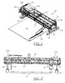
- FIG. 1 a concrete curing and texturing machine 10 embodying the principles of the present invention is shown.
- the curing and texturing machine 10 is shown in FIG. 1 as being disposed in operative position over a section of a concrete roadway, street, runway or bridge deck 11.
- the concrete curing and texturing machine 10 shown in FIG. 1 is drawn by way of illustration and not by way of limitation and may be used on other suitable types of concrete curing and texturing machines wherein the curing machine includes a main trusswork or frame member 12 having ends 12a and 12b, with the main trusswork member extending across and over the surface of the concrete roadway 11.
- the concrete curing and texturing machine 10 includes an elongated trusswork or frame 12 on which may be mounted a texturing or grooving unit 14 (FIGS. 2, 11 and 12) that is movable back and forth between the ends 12a and 12b of the frame 12.
- a sprayboom carriage unit 16 may be mounted to the elongated trusswork or frame 12; however, preferably, the sprayboom carriage unit 16 is mounted to an extension frame member 17 which is mounted to and positioned rearwardly of the elongated trusswork frame 12.
- leg-type supporting units 20, 21, 22, and 23 are leg-type supporting units 20, 21, 22, and 23 of a type known in the art. As shown in FIGS.
- power driven four-track drive units 24 are mounted to the lower end portions of the leg type supporting units 20, 21, 22 and 23 to support and power the concrete curing and texturing machine 10.
- the leg-type supporting units 20-23 are vertically adjustable relative to the four-track units 24 by suitable means for adjusting the proper height of the concrete curing and texturing machine relative to the surface of the finished concrete.
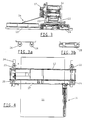
- various types of rubber wheel units 26 (FIG. 3A) or two-track units 28 (FIG. 3B) may be secured to the lower end portions of the leg-type supporting units 20-23 to support and power the curing and texturing machine 10.
- the drive member is a two-track drive member; the curing machine is not driven in a direction parallel to the elongated trusswork or frame 12.
- the drive unit is either a four-track drive unit or a rubber wheel drive unit, the drive unit may be turned 90° to power the curing machine in a direction parallel with the elongated trusswork.
- a sprayboom carriage unit 16 is shown which is mounted to the extension truss member 17 located rearwardly of the concrete curing machine 10.
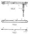
- the sprayboom carriage unit is comprised of a carriage panel 34 which includes side thrust rollers 35 and carriage rollers 36 which mount the carriage panel 34 onto the extension truss member 17.
- Extending rearwardly from the carriage panel 34 is a boom member 38 which is supported by cables 39 to the carriage panel 34.
- a crossbeam 40 At the distal end of the boom member is a crossbeam 40 which is connected by a cable to a hand winch 43 mounted on the carriage panel 34.
- the crossbeam 40 is secured to an elongated boom pipe 42 which includes spray nozzles 44 positioned thereon and extending downwardly therefrom.
- the spray nozzles 44 are equally spaced along the length of the boom pipe 38.
- the hand winch 43 raises and lowers the boom extension member 38 relative to the surface of the poured concrete. This raising and lowering of the boom extension member fixes the height between the boom pipe 42 and spray nozzles 44 and the concrete surface.
- a hood shield member 41 Positioned about the elongated shaped boom pipe and spray nozzles is a hood shield member 41 which reduces the effect of the wind during the application of the curing compound onto the finished concrete.
- a drive motor 30 mounted to the truss member 17 is a drive motor 30 that is operatively connected through a drive sprocket 31, an idler sprocket 33 and a drive chain 32 secured to the carriage panel 34, as will hereinafter be described.
- Actuation of the hydraulic motor 30 turns the drive chain 32 to cause the carriage panel and the suspended sprayboom carriage member 16 to move back and forth across the length of the extension truss member 17.
- the boom member 38 and associated boom pipe and hood shield are removable from the carriage panel by the removal of pins 46 from the aligned bracket members 48 on the carriage panel 34 and boom member 38, as shown in FIG. 9. This permits the curing machine to be reduced in width to permit transport of the curing machine between job sites.
- the elongated trusswork or frame 12 supports a reservoir 29 which contains the curing compound that is uniformly sprayed onto the surface of the finished or grooved concrete.
- the elongated trusswork or frame 12 preferably, also supports the texturing or grooving unit 14 having a plurality of tines 51 thereunder and permits the back and forth travel of the texturing or grooving unit 14 across the surface of the concrete.
- the texturing or grooving unit 14 includes a carriage member 15 and two pairs of outwardly projecting spaced rollers 18 mounted on respective upper ends in a position that the rollers are structurally arranged to be supported and ride along the inner edges of elongated tracks 13 and 13a on opposite sides of the trusswork frame member 12.
- the tracks support the texturing or grooving unit 14 for movement longitudinally of the trusswork frame 12.
- the tracks 13 and 13a support the texturing or grooving unit 14 from the sides of the trusswork frame 13 by vertically adjustable hangars 50 so that the level of tracks 13 and 13a at various points along the elongated trusswork frame 12 may be adjusted, as desired. As shown in FIG.
- a pair of hold down rollers 53 are mounted on each of the ends of the carriage 15 below the pair of upper rollers 51 and 52.
- the rollers are positioned such that when the carriage 15 of the grooving unit 14 is supported on the tracks 13 and 13a, the rollers are in abutting engagement with lower surfaces of the tracks to hold the rollers 53 downwardly against the tracks 13 and 13a.
- the texturing carriage unit 15 suspends and holds a grooving or texturing member 19 to be engageable with the surface of the concrete during each back and forth movement of the texturing unit across the surface of the poured concrete.
- the timed texturing member or comb 19 may be of any length ranging from about 3 to 12 feet in length.
- FIG. 14 illustrates the hydraulic circuitry of the concrete curing machine in accordance with the present invention.
- the hydraulic motor 30 operates to move the sprayboom carriage back and forth across the body of the poured concrete.
- the hydraulic motor 30 provides pressurized hydraulic oil through carriage speed control valve 54 which meters the flow rate for the hydraulic oil communicating with the sprayboom carriage 16.
- carriage speed control valve 54 which meters the flow rate for the hydraulic oil communicating with the sprayboom carriage 16.
- the sprayboom carriage engages a stop or valve members 56 which reverses the operation of the respective carriage to cause the carriage to travel back and forth upon engagement of the carriage stop valves on each end of the curing machine.
- a flow divider member 58 is associated with the speed control valve 54 to provide a control for the texturing unit 14, as shown by the dotted line 60 in FIG. 14. This controls the motor 62 which powers the texturing unit 14 through speed control valve 62. This permits the precise control of the operation and speed of the texturing unit 14 relative to the speed and operation of the sprayboom unit 16.
- the texturing unit and spraying unit operate in tandem on the surface of the finished concrete.
- the curing machine is moved forwardly a distance equal to the length of the texturing comb.
- a hose 64 (FIG. 13) is provided to connect the curing compound reservoir 29 with the boom pipe and spray nozzles such that during the back and forth movement of the sprayboom carriage 16 over the surface of the concrete, a predetermined amount of curing compound may be deposited onto the exposed concrete surface.
- the curing compound is applied to the concrete surface at a rate between approximately 50 square feet to 200 square feet per gallon of curing compound.
- a texturing or grooving unit 14 having a texturing comb 51 may be suspended longitudinally from the elongated trusswork or frame 12 of the curing machine to provide a machine that provides vertical grooves in the concrete, as shown in FIG. 3.
Landscapes
- Engineering & Computer Science (AREA)
- Architecture (AREA)
- Civil Engineering (AREA)
- Structural Engineering (AREA)
- On-Site Construction Work That Accompanies The Preparation And Application Of Concrete (AREA)
- Devices For Post-Treatments, Processing, Supply, Discharge, And Other Processes (AREA)
- Road Paving Machines (AREA)
Applications Claiming Priority (2)
| Application Number | Priority Date | Filing Date | Title |
|---|---|---|---|
| US792270 | 2001-02-24 | ||
| US09/792,270 US6497531B2 (en) | 2001-02-24 | 2001-02-24 | Concrete curing machine |
Publications (2)
| Publication Number | Publication Date |
|---|---|
| EP1234914A2 true EP1234914A2 (fr) | 2002-08-28 |
| EP1234914A3 EP1234914A3 (fr) | 2003-10-08 |
Family
ID=25156315
Family Applications (1)
| Application Number | Title | Priority Date | Filing Date |
|---|---|---|---|
| EP01307995A Withdrawn EP1234914A3 (fr) | 2001-02-24 | 2001-09-19 | Dispositif de protection pour le béton frais |
Country Status (4)
| Country | Link |
|---|---|
| US (1) | US6497531B2 (fr) |
| EP (1) | EP1234914A3 (fr) |
| BR (1) | BR0105978A (fr) |
| CA (1) | CA2357132C (fr) |
Cited By (6)
| Publication number | Priority date | Publication date | Assignee | Title |
|---|---|---|---|---|
| CN101827497A (zh) * | 2010-04-30 | 2010-09-08 | 高德(无锡)电子有限公司 | 印刷线路板行业垂直镀通孔线插筐自动上下料系统 |
| EP2886717A1 (fr) * | 2013-12-23 | 2015-06-24 | Wirtgen GmbH | Machine de post-traitement et procédé destiné au post-traitement d'une couche de béton fraîchement réalisée |
| EP2947206A1 (fr) * | 2014-05-23 | 2015-11-25 | Wirtgen GmbH | Machine de post-traitement et procédé destiné au post-traitement d'une couche de béton fraîchement réalisée |
| DE102015115766A1 (de) * | 2015-09-18 | 2017-03-23 | Dr. Ing. H.C. F. Porsche Aktiengesellschaft | Mobile Montagestation für ein Leitplankensystem und Verfahren zum Verwenden einer solchen |
| CN111608049A (zh) * | 2020-06-01 | 2020-09-01 | 叶小土 | 一种道路施工用混凝土振荡养护辅助装置 |
| CN112030686A (zh) * | 2020-08-29 | 2020-12-04 | 张冰琳 | 一种公路工程施工用路面混凝土养护装置 |
Families Citing this family (42)
| Publication number | Priority date | Publication date | Assignee | Title |
|---|---|---|---|---|
| DE10128564B4 (de) * | 2001-06-13 | 2005-10-27 | Wirtgen Gmbh | Gleitschalungsfertiger |
| US7121761B2 (en) * | 2003-05-28 | 2006-10-17 | Woodruff Paul N | Paved surface configured for reducing tire noise and increasing tire traction and method and apparatus of manufacturing same |
| CA2455011C (fr) | 2004-01-09 | 2011-04-05 | Suncor Energy Inc. | Traitement de mousse bitumineuse par injection de vapeur en ligne |
| US7420769B2 (en) * | 2004-04-13 | 2008-09-02 | Seagate Technology Llc | Data storage device enclosure with overmolded connector to provide conductive lead support |
| US7517171B2 (en) * | 2006-06-07 | 2009-04-14 | Gomaco Corporation, A Div. Of Godbersen Smith Construction Co. | Powered broom shift |
| US8073566B2 (en) | 2007-04-05 | 2011-12-06 | Power Curbers, Inc. | Automated stringline installation system |
| US10198741B2 (en) | 2009-04-06 | 2019-02-05 | Wendell D. Brown | Method and apparatus for content presentation in association with a communication connection |
| KR101187558B1 (ko) * | 2009-04-28 | 2012-10-04 | 주식회사 이레하이테크이앤씨 | 종 방향 타이닝 설비 |
| US20110182664A1 (en) * | 2010-01-21 | 2011-07-28 | Stephen John Brodie | Sealant deploying apparatus and method |
| KR101198292B1 (ko) * | 2010-04-28 | 2012-11-07 | 태륭건설(주) | 미끄럼 방지 줄눈 성형장치 |
| US20130122186A1 (en) | 2011-11-10 | 2013-05-16 | Hoppel Fabrication Specialties, Inc. | Method and apparatus for coating horizontal surfaces |
| US8834064B2 (en) * | 2012-01-16 | 2014-09-16 | Cmi Terex Corporation | Integrated carriage fogging system for concrete pavers |
| DE102012214929A1 (de) | 2012-08-22 | 2014-02-27 | Wirtgen Gmbh | Straßenfräsmaschine zum Bearbeiten von Straßenbelägen, sowie Verfahren zum Verschwenken eines Laufwerks einer Straßenfräsmaschine |
| US9051696B1 (en) * | 2013-02-04 | 2015-06-09 | Gomaco Corporation | Modular configurable paving apparatus and modular configurable paving operation system |
| DE102013216950A1 (de) | 2013-08-26 | 2015-02-26 | Wirtgen Gmbh | Gleitschalungsfertiger, sowie Verfahren zur Anpassung der Breite einer Muldeneinrichtung |
| US10132046B2 (en) * | 2015-04-20 | 2018-11-20 | Wirtgen Gmbh | Concrete texturing machine |
| US10377233B2 (en) * | 2016-03-10 | 2019-08-13 | Gettle Incorporated | Utility table |
| US11104035B1 (en) | 2017-08-08 | 2021-08-31 | Oshkosh Corporation | Mixer drum drive with variable displacement motor |
| WO2019200376A1 (fr) * | 2018-04-13 | 2019-10-17 | Gomaco Corporation | Dispositif de finition de pont tridimensionnel |
| DE102019204259A1 (de) * | 2019-03-27 | 2020-10-01 | Putzmeister Engineering Gmbh | Extrudervorrichtung, Extrudersystem und Verwendung einer Extrudervorrichtung und/oder eines Extrudersystems |
| CN110396905A (zh) * | 2019-08-15 | 2019-11-01 | 张德明 | 一种道路桥梁工程用混凝土路面养护装置 |
| US11162233B2 (en) | 2019-12-05 | 2021-11-02 | Wirtgen Gmbh | Adjustable width mold |
| US11339541B2 (en) | 2019-12-05 | 2022-05-24 | Wirtgen Gmbh | Adjustable width mold |
| US11702803B2 (en) * | 2020-01-24 | 2023-07-18 | Gomaco Corporation | High-production truss-mounted screed assembly |
| US20230323613A1 (en) * | 2020-01-24 | 2023-10-12 | Gomaco Corporation | High-production truss-mounted screed assembly |
| CN111827049A (zh) * | 2020-06-24 | 2020-10-27 | 石卫东 | 一种摊铺机螺旋叶片以及摊铺机 |
| CN111877106B (zh) * | 2020-07-17 | 2022-06-24 | 新政建设集团有限公司 | 一种道路施工用定位抹水泥装置 |
| CN111962364A (zh) * | 2020-08-29 | 2020-11-20 | 陈建军 | 一种混凝土养护用喷水装置 |
| US12378733B1 (en) | 2020-12-10 | 2025-08-05 | Allen Engineering Corp. | Bridge deck paver with enhanced hydraulic shifting |
| CN113355982B (zh) * | 2021-03-10 | 2023-06-09 | 广东辰集建设工程有限公司 | 一种混凝土施工浇筑用辅助压痕设备及其快速压痕方法 |
| CN113090051A (zh) * | 2021-04-01 | 2021-07-09 | 尹京璞 | 节能型土建施工用混凝土浇水装置 |
| CN113119298B (zh) * | 2021-04-21 | 2022-12-13 | 英索来欣(盐城)新材料科技有限公司 | 一种全自动制作空心板的机器 |
| US20230073953A1 (en) * | 2021-09-03 | 2023-03-09 | Scott Swederski | Concrete surface treatment system and method |
| CN114233025B (zh) * | 2021-12-21 | 2023-06-27 | 保定保竣混凝土搅拌有限公司 | 一种混凝土离心保养装置 |
| DE102021134452B4 (de) | 2021-12-23 | 2024-02-22 | Wirtgen Gmbh | Gleitschalungsfertiger |
| US12516480B2 (en) | 2022-03-22 | 2026-01-06 | Wirtgen Gmbh | Slipform paver with suspended adjustable width mold |
| CN114808610A (zh) * | 2022-05-16 | 2022-07-29 | 酒泉职业技术学院(甘肃广播电视大学酒泉市分校) | 一种混凝土压花路面施工装置 |
| DE102022123625B3 (de) * | 2022-09-15 | 2023-12-14 | Wirtgen Gmbh | Nachbehandlungsmaschine |
| CN115450450B (zh) * | 2022-10-26 | 2024-04-02 | 临清市安竣建设有限公司 | 一种混凝土建筑结构的节水型喷淋养护设备 |
| CN117166370B (zh) * | 2023-08-18 | 2025-12-26 | 山东省路桥集团有限公司 | 一种大挑臂倒t形预应力混凝土盖梁施工养护装置 |
| CN118498170B (zh) * | 2024-07-16 | 2024-10-25 | 保利长大工程有限公司 | 路面水稳施工侧膜成型装置及工艺 |
| CN118814577B (zh) * | 2024-09-19 | 2025-02-11 | 山东绿建新材料有限公司 | 一种便捷式混凝土路面成型后养护装置 |
Family Cites Families (32)
| Publication number | Priority date | Publication date | Assignee | Title |
|---|---|---|---|---|
| US2367594A (en) * | 1943-04-01 | 1945-01-16 | Truscon Lab Inc | Spraying apparatus |
| GB1143953A (en) * | 1965-05-31 | 1969-02-26 | Robert Mcgregor & Sons Ltd | Improvements in or relating to the surface treatment of concrete roads and the like |
| FR1454736A (fr) * | 1965-11-15 | 1966-02-11 | Abg Werke Gmbh | Engin de pulvérisation, notamment pour le post-traitement de chaussées fraîchement bétonnées |
| BE758345R (fr) * | 1969-11-12 | 1971-05-03 | Shell Int Research | |
| US3874806A (en) * | 1972-07-27 | 1975-04-01 | Cmi Corp | Apparatus for grooving pavement |
| FR2209009B1 (fr) | 1972-08-22 | 1975-01-03 | Screg | |
| US4070128A (en) | 1976-03-25 | 1978-01-24 | Garrison Harry F | Multiple-groover for pavements |
| US4297399A (en) | 1980-01-08 | 1981-10-27 | Martin Marietta Corporation | Method for curing concrete |
| US4318631A (en) | 1980-01-21 | 1982-03-09 | Vickers Richard R | Texturing broom apparatus for roadway pavements |
| US4541750A (en) * | 1981-09-24 | 1985-09-17 | Master Consolidated Corporation | Surface spreader with column bypass |
| US4411554A (en) * | 1981-10-21 | 1983-10-25 | Gratzfeld Edward P | Material spreader and bridge |
| US4449667A (en) * | 1982-04-26 | 1984-05-22 | Lor-Al Corporation | Apparatus for folding an outboard boom on a liquid spraying implement |
| US4572704A (en) * | 1983-01-13 | 1986-02-25 | Allen Engineering Corporation | High density concrete placing and finishing machine |
| US4555200A (en) * | 1984-03-26 | 1985-11-26 | Morrison Donald R | Hydraulically-powered material spreader |
| FR2571986B1 (fr) * | 1984-10-18 | 1987-08-21 | Beugnet Sa | Machine de repandage d'un produit liquide sur une surface tel que du produit de cure sur des dalles en beton de ciment |
| US4607979A (en) * | 1984-12-21 | 1986-08-26 | Morrison Donald R | Hydraulically-powered rock spreader |
| US4571120A (en) * | 1985-01-07 | 1986-02-18 | International Technology Services | Road levelling oil squeegee |
| US4657431A (en) * | 1986-03-19 | 1987-04-14 | Morrison Donald R | Non-uniform size particulate spreader |
| US4822210A (en) * | 1986-10-10 | 1989-04-18 | Rotec Industries | Concrete finishing machine |
| CA1283676C (fr) * | 1987-05-14 | 1991-04-30 | D. Gavin Semple | Ecran sur rampe d'arrosage |
| US4960242A (en) * | 1988-07-28 | 1990-10-02 | Rosco Manufacturing Company | Asphalt distributor |
| US4968099A (en) | 1989-02-14 | 1990-11-06 | Target Products Inc. | Fluid control system for roadway grooving apparatus |
| US5187882A (en) | 1989-02-17 | 1993-02-23 | Cam Sales, Inc. | System for curing concrete articles |
| WO1991001432A1 (fr) * | 1989-07-21 | 1991-02-07 | Australian Stone Technology | Procede et appareil servant a tailler des materiaux erodables en utilisant des moyens d'eau a haute pression |
| DE4016545A1 (de) * | 1990-05-18 | 1991-11-21 | Horst Lienhop | Giesswagen |
| FR2662193B1 (fr) * | 1990-05-21 | 1992-10-30 | Colas Sa | Dispositif d'epandage d'un materiau fluide, notamment d'une emulsion d'accrochage d'enrobes bitumineux et machine de construction de chaussees comportant un tel dispositif. |
| US5249886A (en) | 1992-02-14 | 1993-10-05 | Huerta Jr Francisco C | Grooving apparatus |
| US5348226A (en) * | 1992-11-12 | 1994-09-20 | Rhs Fertilizing/Spraying Systems | Spray boom system with automatic boom end height control |
| US5590977A (en) * | 1995-05-25 | 1997-01-07 | Guntert & Zimmerman Constr. Div. Inc. | Four track paving machine and process of transport |
| US5707179A (en) | 1996-03-20 | 1998-01-13 | Bruckelmyer; Mark | Method and apparaatus for curing concrete |
| US5957621A (en) * | 1997-02-20 | 1999-09-28 | Clark, Jr.; Albert J. | System for applying liquid asphalt to a roadbed |
| US5855978A (en) | 1997-05-16 | 1999-01-05 | Midwest Canvas Corp. | Concrete cure blanket having integral heat reflective means |
-
2001
- 2001-02-24 US US09/792,270 patent/US6497531B2/en not_active Expired - Lifetime
- 2001-09-07 CA CA002357132A patent/CA2357132C/fr not_active Expired - Fee Related
- 2001-09-19 EP EP01307995A patent/EP1234914A3/fr not_active Withdrawn
- 2001-11-22 BR BR0105978-5A patent/BR0105978A/pt not_active Application Discontinuation
Cited By (9)
| Publication number | Priority date | Publication date | Assignee | Title |
|---|---|---|---|---|
| CN101827497A (zh) * | 2010-04-30 | 2010-09-08 | 高德(无锡)电子有限公司 | 印刷线路板行业垂直镀通孔线插筐自动上下料系统 |
| CN101827497B (zh) * | 2010-04-30 | 2012-05-23 | 高德(无锡)电子有限公司 | 印刷线路板行业垂直镀通孔线插筐自动上下料系统 |
| EP2886717A1 (fr) * | 2013-12-23 | 2015-06-24 | Wirtgen GmbH | Machine de post-traitement et procédé destiné au post-traitement d'une couche de béton fraîchement réalisée |
| US9399842B2 (en) | 2013-12-23 | 2016-07-26 | Wirtgen Gmbh | Texture curing machine as well as method for the subsequent treatment of a freshly produced concrete layer |
| EP2947206A1 (fr) * | 2014-05-23 | 2015-11-25 | Wirtgen GmbH | Machine de post-traitement et procédé destiné au post-traitement d'une couche de béton fraîchement réalisée |
| DE102015115766A1 (de) * | 2015-09-18 | 2017-03-23 | Dr. Ing. H.C. F. Porsche Aktiengesellschaft | Mobile Montagestation für ein Leitplankensystem und Verfahren zum Verwenden einer solchen |
| CN111608049A (zh) * | 2020-06-01 | 2020-09-01 | 叶小土 | 一种道路施工用混凝土振荡养护辅助装置 |
| CN111608049B (zh) * | 2020-06-01 | 2021-04-16 | 济南通达公路工程有限公司 | 一种道路施工用混凝土振荡养护辅助装置 |
| CN112030686A (zh) * | 2020-08-29 | 2020-12-04 | 张冰琳 | 一种公路工程施工用路面混凝土养护装置 |
Also Published As
| Publication number | Publication date |
|---|---|
| BR0105978A (pt) | 2002-10-01 |
| US20020119004A1 (en) | 2002-08-29 |
| CA2357132A1 (fr) | 2002-08-24 |
| EP1234914A3 (fr) | 2003-10-08 |
| US6497531B2 (en) | 2002-12-24 |
| CA2357132C (fr) | 2007-12-11 |
Similar Documents
| Publication | Publication Date | Title |
|---|---|---|
| US6497531B2 (en) | Concrete curing machine | |
| US7748789B2 (en) | Pavement profiler | |
| US9028168B1 (en) | Concrete finishing machine | |
| US9127418B2 (en) | Independently supported concrete saw apparatus and method | |
| US4470783A (en) | Apparatus for screeding and leveling | |
| US11161793B2 (en) | Median barrier finishing machine | |
| KR101025279B1 (ko) | 승강식 도료분사장치가 구성된 융착식 스프레이 도색차량 | |
| US6234713B1 (en) | Vibrator truss assembly | |
| JP7009999B2 (ja) | 塗装装置および塗装方法 | |
| US4256415A (en) | Concrete vibrator machine | |
| US3398663A (en) | Pavement finishing apparatus | |
| CA2271371C (fr) | Methode et appareil d'hydrodemolition a multiple jets | |
| CN211734970U (zh) | 一种电液控制抹平装置及混凝土滑模摊铺机 | |
| DE19903638A1 (de) | Vorrichtung zum Glätten einer Betonbelagsoberfläche | |
| GB2080374A (en) | Apparatus for Levelling a Surface | |
| CN108677669B (zh) | 一种市政道路养护设备 | |
| JP4326544B2 (ja) | アスファルトフィニッシャにおけるアスファルト乳剤散布装置 | |
| CN114856225A (zh) | 一种混凝土自动化养护装置及其使用方法 | |
| CN111236088B (zh) | 砼护栏养护装置 | |
| CN218905778U (zh) | 一种桥梁伸缩缝混凝土养护装置 | |
| CN110904792A (zh) | 一种电液控制抹平装置及混凝土滑模摊铺机 | |
| US3220321A (en) | Concrete surfacing apparatus | |
| US11767643B2 (en) | Versatile light rail bed paver | |
| US20100247241A1 (en) | Machine for paving concrete paths | |
| US12378733B1 (en) | Bridge deck paver with enhanced hydraulic shifting |
Legal Events
| Date | Code | Title | Description |
|---|---|---|---|
| PUAI | Public reference made under article 153(3) epc to a published international application that has entered the european phase |
Free format text: ORIGINAL CODE: 0009012 |
|
| AK | Designated contracting states |
Kind code of ref document: A2 Designated state(s): AT BE CH CY DE DK ES FI FR GB GR IE IT LI LU MC NL PT SE TR |
|
| AX | Request for extension of the european patent |
Free format text: AL;LT;LV;MK;RO;SI |
|
| PUAL | Search report despatched |
Free format text: ORIGINAL CODE: 0009013 |
|
| AK | Designated contracting states |
Kind code of ref document: A3 Designated state(s): AT BE CH CY DE DK ES FI FR GB GR IE IT LI LU MC NL PT SE TR |
|
| AX | Request for extension of the european patent |
Extension state: AL LT LV MK RO SI |
|
| AKX | Designation fees paid | ||
| REG | Reference to a national code |
Ref country code: DE Ref legal event code: 8566 |
|
| STAA | Information on the status of an ep patent application or granted ep patent |
Free format text: STATUS: THE APPLICATION IS DEEMED TO BE WITHDRAWN |
|
| 18D | Application deemed to be withdrawn |
Effective date: 20040409 |