EP1234152B1 - Durchlaufofen für rohrförmiges brenngut - Google Patents
Durchlaufofen für rohrförmiges brenngut Download PDFInfo
- Publication number
- EP1234152B1 EP1234152B1 EP00965775A EP00965775A EP1234152B1 EP 1234152 B1 EP1234152 B1 EP 1234152B1 EP 00965775 A EP00965775 A EP 00965775A EP 00965775 A EP00965775 A EP 00965775A EP 1234152 B1 EP1234152 B1 EP 1234152B1
- Authority
- EP
- European Patent Office
- Prior art keywords
- furnace
- conveyor
- channel
- transport
- opening
- Prior art date
- Legal status (The legal status is an assumption and is not a legal conclusion. Google has not performed a legal analysis and makes no representation as to the accuracy of the status listed.)
- Expired - Lifetime
Links
- 238000010304 firing Methods 0.000 title claims abstract description 35
- 239000000463 material Substances 0.000 title description 30
- 229910010293 ceramic material Inorganic materials 0.000 claims description 5
- 239000011214 refractory ceramic Substances 0.000 claims description 3
- 229910052572 stoneware Inorganic materials 0.000 description 12
- 239000000446 fuel Substances 0.000 description 7
- 239000000919 ceramic Substances 0.000 description 3
- 238000005096 rolling process Methods 0.000 description 3
- 238000001816 cooling Methods 0.000 description 2
- 238000010438 heat treatment Methods 0.000 description 2
- 238000010276 construction Methods 0.000 description 1
- 239000002184 metal Substances 0.000 description 1
- 239000007769 metal material Substances 0.000 description 1
- 230000000630 rising effect Effects 0.000 description 1
- 239000010865 sewage Substances 0.000 description 1
- 238000005245 sintering Methods 0.000 description 1
- 230000003068 static effect Effects 0.000 description 1
- 230000001360 synchronised effect Effects 0.000 description 1
Images

Classifications
-
- F—MECHANICAL ENGINEERING; LIGHTING; HEATING; WEAPONS; BLASTING
- F27—FURNACES; KILNS; OVENS; RETORTS
- F27B—FURNACES, KILNS, OVENS OR RETORTS IN GENERAL; OPEN SINTERING OR LIKE APPARATUS
- F27B9/00—Furnaces through which the charge is moved mechanically, e.g. of tunnel type; Similar furnaces in which the charge moves by gravity
- F27B9/14—Furnaces through which the charge is moved mechanically, e.g. of tunnel type; Similar furnaces in which the charge moves by gravity characterised by the path of the charge during treatment; characterised by the means by which the charge is moved during treatment
- F27B9/20—Furnaces through which the charge is moved mechanically, e.g. of tunnel type; Similar furnaces in which the charge moves by gravity characterised by the path of the charge during treatment; characterised by the means by which the charge is moved during treatment the charge moving in a substantially straight path
- F27B9/26—Furnaces through which the charge is moved mechanically, e.g. of tunnel type; Similar furnaces in which the charge moves by gravity characterised by the path of the charge during treatment; characterised by the means by which the charge is moved during treatment the charge moving in a substantially straight path on or in trucks, sleds, or containers
- F27B9/262—Furnaces through which the charge is moved mechanically, e.g. of tunnel type; Similar furnaces in which the charge moves by gravity characterised by the path of the charge during treatment; characterised by the means by which the charge is moved during treatment the charge moving in a substantially straight path on or in trucks, sleds, or containers on or in trucks
-
- F—MECHANICAL ENGINEERING; LIGHTING; HEATING; WEAPONS; BLASTING
- F27—FURNACES; KILNS; OVENS; RETORTS
- F27B—FURNACES, KILNS, OVENS OR RETORTS IN GENERAL; OPEN SINTERING OR LIKE APPARATUS
- F27B9/00—Furnaces through which the charge is moved mechanically, e.g. of tunnel type; Similar furnaces in which the charge moves by gravity
- F27B9/14—Furnaces through which the charge is moved mechanically, e.g. of tunnel type; Similar furnaces in which the charge moves by gravity characterised by the path of the charge during treatment; characterised by the means by which the charge is moved during treatment
- F27B9/20—Furnaces through which the charge is moved mechanically, e.g. of tunnel type; Similar furnaces in which the charge moves by gravity characterised by the path of the charge during treatment; characterised by the means by which the charge is moved during treatment the charge moving in a substantially straight path
- F27B9/22—Furnaces through which the charge is moved mechanically, e.g. of tunnel type; Similar furnaces in which the charge moves by gravity characterised by the path of the charge during treatment; characterised by the means by which the charge is moved during treatment the charge moving in a substantially straight path on rails, e.g. under the action of scrapers or pushers
- F27B9/227—Furnaces through which the charge is moved mechanically, e.g. of tunnel type; Similar furnaces in which the charge moves by gravity characterised by the path of the charge during treatment; characterised by the means by which the charge is moved during treatment the charge moving in a substantially straight path on rails, e.g. under the action of scrapers or pushers with rotation of the charge
-
- F—MECHANICAL ENGINEERING; LIGHTING; HEATING; WEAPONS; BLASTING
- F27—FURNACES; KILNS; OVENS; RETORTS
- F27B—FURNACES, KILNS, OVENS OR RETORTS IN GENERAL; OPEN SINTERING OR LIKE APPARATUS
- F27B9/00—Furnaces through which the charge is moved mechanically, e.g. of tunnel type; Similar furnaces in which the charge moves by gravity
- F27B9/14—Furnaces through which the charge is moved mechanically, e.g. of tunnel type; Similar furnaces in which the charge moves by gravity characterised by the path of the charge during treatment; characterised by the means by which the charge is moved during treatment
- F27B9/20—Furnaces through which the charge is moved mechanically, e.g. of tunnel type; Similar furnaces in which the charge moves by gravity characterised by the path of the charge during treatment; characterised by the means by which the charge is moved during treatment the charge moving in a substantially straight path
- F27B9/24—Furnaces through which the charge is moved mechanically, e.g. of tunnel type; Similar furnaces in which the charge moves by gravity characterised by the path of the charge during treatment; characterised by the means by which the charge is moved during treatment the charge moving in a substantially straight path being carried by a conveyor
- F27B9/2461—Furnaces through which the charge is moved mechanically, e.g. of tunnel type; Similar furnaces in which the charge moves by gravity characterised by the path of the charge during treatment; characterised by the means by which the charge is moved during treatment the charge moving in a substantially straight path being carried by a conveyor the charge being suspended from the conveyor
-
- F—MECHANICAL ENGINEERING; LIGHTING; HEATING; WEAPONS; BLASTING
- F27—FURNACES; KILNS; OVENS; RETORTS
- F27D—DETAILS OR ACCESSORIES OF FURNACES, KILNS, OVENS OR RETORTS, IN SO FAR AS THEY ARE OF KINDS OCCURRING IN MORE THAN ONE KIND OF FURNACE
- F27D3/00—Charging; Discharging; Manipulation of charge
- F27D3/12—Travelling or movable supports or containers for the charge
- F27D3/123—Furnace cars
Definitions
- the invention relates to a continuous furnace for tubular fuel, in particular rotationally symmetrical fired goods, such as stoneware pipes.
- GB-A-2 021 743 is a continuous furnace for tubular fuel known in which the tubular body lying and rolling through the Oven are moved.
- GB-A-2 149 074 is a tunnel kiln with a known conveyor arranged on the ceiling.
- the invention is accordingly based on the object to specify a continuous furnace for tubular fuel, the shortest possible passage times through the furnace enables and a deformation of the firing material largely prevented.
- the invention lies in the following Consideration: When transporting the Fired goods through the oven can already pass through Gravitational influences in the temperature range mentioned a deformation. This applies to both standing as for a hanging transport of the Combustible material.
- a lying transport on a kiln car as it is known for example from fine ceramics, is out of the question because given the length of the Kiln wagons of correspondingly wide kiln cars are used should be. This would require the big one Mass of these kiln cars to heat up with to cool down what is not energetically justifiable.
- the invention is based on the consideration of one "static" transport of the firing material through the furnace, at where the firing material is in the same position on or remains on a transport device by a to replace “at least partially rotating” transport, where the firing stock as it passes through the furnace at least in the furnace zone where it is susceptible to Deformation is caused to rotate.
- Firing material on a corresponding transport device be guided horizontally through the furnace duct, whereby a facility is provided along the transport route is on which the firing material with a freely accessible Section (i.e. outside the support areas in the Transport unit), whereby it is (slightly) detaches from the support areas of the transport device (takes off) and then rolling on this facility (rotating) passed through the transport device becomes.
- a freely accessible Section i.e. outside the support areas in the Transport unit
- the Transport device through the furnace floor.
- a two-part Transport device are provided, each being Part through a corresponding opening in the furnace floor or the furnace ceiling extends.
- the openings can be adjacent (and parallel) to every oven wall.
- “Neighbor” means that the tubular fuel, the length of which is usually only slightly smaller than the width of the Flow channel should be the appropriate one Slightly protrude from the transport sections at the ends.
- the associated transport section outstanding part of the kiln, for example end flange area of a stoneware sewage pipe his. This ensures that the Firing material is guided exactly horizontally.
- the transport units can over the ends of the Continue flow channel through to a appropriate loading and unloading with firing material facilitate. You can then click above, next to or below the oven to the oven entrance to be led back.
- the transport sections of the transport unit can one in the axial direction of the flow channel extending frame consist of at least one has horizontally extending lower leg which can be placed on the kiln.
- the transport section can also be two, vertically to the axial direction of the flow channel at a distance mutually arranged support arms for the firing material include.
- the transport sections can accommodate one or be formed several pieces of firing material, also in In the case of several items of firing material, these side by side along a horizontal plane).
- the conveyor section of the transport unit can roll or Wheels for guiding along corresponding rails exhibit.
- the transport unit above the furnace ceiling - similar to one Schwebebahn - Have wheels that run on rails become.
- a corresponding drive can be via a Push device, a revolving chain or the like respectively.
- an embodiment provides that Gas-tight opening in relation to the flow channel train. This can be done through an appropriate meandering course of the transport unit through the Opening and / or seals take place, as a rule a relative gas tightness is sufficient.
- This Furnishing can consist of a table facing End sections (furnace entrance, furnace exit) of the Flow channel inclined towards the furnace bottom Inclined surfaces.
- the arrangement of the inclined surfaces can be such that the free ends below the in the Transport device arranged overlying fired goods are. This ensures that the Only then when the firing material is transported through the furnace onto the first sloping surface (increasing in the direction of transport) accumulates when the firing material is already above this Sloping surface has arrived. In this way, a the material to be fired gently onto the inclined surface allows.
- the transport unit will move it further in the direction Furnace exit transported and due to the rising Sloping surface slightly from the support areas of the Transport unit loosened (lifted off) so that the fired goods now only rests on the inclined surface. While further transport, the fired goods roll due to the Stiction to the inclined surface over this up to the highest point before it is tilted over the inverse subsequent inclined surface rolls accordingly before it returns to the support areas of the Transport unit comes to rest and then with Using the transport unit to the furnace exit is transported.
- the facility mentioned in Case of the treatment of ceramic firing material
- the facility mentioned extend in particular along the furnace part in which Temperatures of over 800 ° C, for example, So along the furnace area in which the furnace temperature above the softening temperature of the firing material lies.
- the device runs centrally between the furnace walls. It is advantageous design the facility as wide as possible in order to provide the largest possible contact surface for the firing material. According to one embodiment, the device should have a width which corresponds to at least half the length of the material to be burned.
- At least the part of each projecting into the flow channel Transport section can be made from a refractory ceramic material exist, especially if the maximum temperatures in the furnace above Softening temperatures of metallic materials are.
- the facility can or must accordingly from one fireproof ceramic material.
- the transport unit and the facility for example metallic or high temperature resistant materials be used.
- the device mentioned can be between the said inclined surfaces a horizontal Have section or alternately inclined Inclined surfaces (in the direction of transport of the firing material) include.
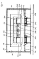
- reference number 10 describes one Oven ceiling, the reference numeral 12 a furnace floor and the Reference numerals 14, 16 corresponding furnace walls.
- furnace channel 18 which from an oven entrance (not shown) to one Oven exit (not shown) extends.
- Openings 20 are formed, which extend over the entire length of the furnace floor 12 in the axial direction of the furnace channel 18 extend.
- Two extend through openings 20
- Transport units 22L, 22R Both are identical and will be explained below with reference to the transport unit 22R described.
- the transport unit 22R comprises two, in Distance between cheeks 24L, 24R.
- the after Section 24U protruding below over furnace bottom 12 forms a conveyor section and is accordingly Trained wheels that run on associated rails (the rails in turn in the axial direction of the Kiln channel 18).
- Section 240 projecting upward from furnace bottom 12 serves as a transport section, the cheeks 24L, 24R U-shaped at its upper end (vertical in one view to the axial direction of the furnace channel) are formed and so serve the horizontal reception of a stoneware pipe 26, which accordingly has four contact surfaces (in the area one cheek 24L, 24R is guided).
- A runs between the transport units 22L, 22R Table 28, which rests on three columns 28S.
- the table 28 is in the transport direction of the stoneware pipe 26 (and correspondingly in the axial direction of the furnace channel 18) designed as follows: it has a first inclined surface, the deepest end below the support areas of the Stoneware pipe 26 and the highest end at least is a few centimeters above these support areas. It another inclined surface closes (mirror image to the former), which accordingly in Transport direction of the stoneware pipe 26 drops.
- Sections 12L, 12M and 12R are supported by a metal frame structure 30 from supported at the bottom.
- the transport unit 32 shown in Figure 2 exists of two conveyor sections 32L, 32R, which the Conveying sections 24U functional according to Figure 1 correspond.
- Rollers 34 are arranged on these conveyor sections, those on rails (not shown) above one Oven ceiling run.
- the transport unit 32 moved along the furnace duct, the stoneware pipes 26, as described in the exemplary embodiment according to FIG. 1, again in the area of the firing zone on a table 28 type described above run off this and rotating (around your respective axis) on the table.
Landscapes
- Engineering & Computer Science (AREA)
- Mechanical Engineering (AREA)
- General Engineering & Computer Science (AREA)
- Tunnel Furnaces (AREA)
- Furnace Charging Or Discharging (AREA)
- Vertical, Hearth, Or Arc Furnaces (AREA)
Description
- einen Ofenboden,
- eine Ofendecke,
- zwei, den Ofenboden mit der Ofendecke unter Ausbildung eines Durchlaufkanals verbindenden Ofenseitenwänden,
- der Ofenboden weist mindestens eine, in Axialrichtung des Durchlaufkanals durchgehend verlaufende Öffnung auf,
- mindestens eine Transporteinheit ist vorgesehen, die sich von einem Förderabschnitt unterhalb des Ofenbodens durch die Öffnung hindurch bis zu einem Transportabschnitt im Durchlaufkanal erstreckt, und
- entlang der Öffnung verfahrbar ist,
- der Transportabschnitt ist zur horizontalen Aufnahme mindestens eines rohrförmigen Brennguts ausgebildet,
- im Durchlaufkanal ist unterhalb mindestens eines frei zugänglichen Abschnitts des Brenngutes mindestens eine Einrichtung angeordnet, entlang der das Brenngut mit seinem frei zugänglichen Abschnitt beim Transport entlang des Durchlaufkanals zunächst rollend aufläuft und anschließend rollend abläuft.
- anstelle des Ofenbodens weist die Ofendecke mindestens eine, in Axialrichtung des Durchlaufkanals durchgehend verlaufende Öffnung auf,
- es ist mindestens eine Transporteinheit vorgesehen, die sich von einem Förderabschnitt oberhalb der Ofendecke durch die Öffnung hindurch bis zu einem Transportabschnitt im Durchlaufkanal erstreckt.
die Einrichtung so breit wie möglich auszubilden, um eine möglichst große Auflagefläche für das Brenngut zur Verfügung zu stellen. Nach einer Ausführungsform soll die Einrichtung eine Breite aufweisen, die mindestens der halben Länge des Brenngutes entspricht.
- Figur 1:
- einen Schnitt durch eine erste Ausführungsform eines Durchlaufofens im Bereich seiner Brennzone.
- Figur 2:
- eine Transporteinheit für eine zweite Ausführungsform eines Durchlaufofens.
Claims (16)
- Durchlaufofen für rohrförmiges Brenngut (26) mit folgenden Merkmalen:1.1.1 einem Ofenboden (12),1.1.2 einer Ofendecke (10),1.1.3 zwei, den Ofenboden (12) mit der Ofendecke (10) unter Ausbildung eines Durchlaufkanals (18) verbindenden Ofenseitenwänden (14, 16),1.2 der Ofenboden (12) weist mindestens eine, in Axialrichtung des Durchlaufkanals (18) durchgehend verlaufende Öffnung (20) auf,1.3.1 mindestens einer Transporteinheit (22L, 22R), die sich von einem Förderabschnitt (24U) unterhalb des Ofenbodens (12) durch die Öffnung (20) hindurch bis zu einem Transportabschnitt (240) im Durchlaufkanal (18) erstreckt, und1.3.2 entlang der Öffnung (20) verfahrbar ist,1.4 der Transportabschnitt (240) ist zur horizontalen Aufnahme mindestens eines rohrförmigen Brennguts (26) ausgebildet,1.5 im Durchlaufkanal (18) ist unterhalb mindestens eines frei zugänglichen Abschnitts des Brennguts (26) mindestens eine Einrichtung (28) angeordnet, entlang der das Brenngut (26) mit seinem frei zugänglichen Abschnitt beim Transport entlang des Durchlaufkanals (18) zunächst rollend aufläuft und anschließend rollend abläuft.
- Durchlaufofen für rohrförmiges Brenngut (26), mit folgenden Merkmalen:2.1.1 einem Ofenboden (12),2.1.2 einer Ofendecke (10),2.1.3 zwei, den Ofenboden (12) mit der Ofendecke (10) unter Ausbildung eines Durchlaufkanals (18) verbindenden Ofenseitenwänden (14, 16),2.2 die Ofendecke (10) weist mindestens eine, in Axialrichtung des Durchlaufkanals (18) durchgehend verlaufende Öffnung auf,2.3.1 mindestens einer Transporteinheit (32), die sich von einem Förderabschnitt (32L, 32R) oberhalb der Ofendecke (18) durch die Öffnung hindurch bis zu einem Transportabschnitt (38) im Durchlaufkanal (18) erstreckt, und2.3.2 entlang der Öffnung (20) verfahrbar ist,2.4 der Transportabschnitt (240) ist zur horizontalen Aufnahme mindestens eines rohrförmigen Brennguts (26) ausgebildet,2.5 im Durchlaufkanal (18) ist unterhalb mindestens eines frei zugänglichen Abschnitts des Brennguts (26) mindestens eine Einrichtung (28) angeordnet, entlang der das Brenngut (26) mit seinem frei zugänglichen Abschnitt beim Transport entlang des Durchlaufkanals (18) zunächst rollend aufläuft und anschließend rollend abläuft.
- Durchlaufofen nach Anspruch 1 oder 2 mit einer zweiteiligen Transporteinheit (22L, 22R; 32), wobei jeder Teil (22L, 22R; 32L, 32R) sich durch eine korrespondierende Öffnung (20) erstreckt.
- Durchlaufofen nach Anspruch 3, wobei die Öffnungen (20) benachbart jeder Ofenwand (14, 16) verlaufen.
- Durchlaufofen nach Anspruch 1 oder 2, bei dem der Transportabschnitt (240, 38) der Transporteinheit (22L, 22R; 32) aus einem sich in Axialrichtung des Durchlaufkanals (18) erstreckenden Rahmen mit einem horizontal verlaufenden unteren Schenkel (38U) besteht.
- Durchlaufofen nach Anspruch 1 oder 2, bei dem der Transportabschnitt (38) zur Aufnahme mehrerer Stücke Brenngut (26) nebeneinander ausgebildet ist.
- Durchlaufofen nach Anspruch 1 oder 2, bei dem der Förderabschnitt (24U; 32L, 32R) der Transporteinheit (24L, 24R; 32) Rollen oder Räder (34) zur Führung entlang korrespondierender Schienen aufweist.
- Durchlaufofen nach Anspruch 1 oder 2, bei dem die Öffnung (20) gasdicht gegenüber dem Durchlaufkanal (18) ausgebildet ist.
- Durchlaufofen nach Anspruch 1 oder 2, bei dem die Einrichtung (28) aus einem Tisch besteht, der zu Endabschnitten des Durchlaufkanals (18) in Richtung auf den Ofenboden (12) geneigte Schrägflächen aufweist.
- Durchlaufofen nach Anspruch 9, bei dem die Schrägflächen im Bereich ihrer freien Enden unterhalb des im Transportabschnitt (240, 38) aufliegenden Brennguts (26) angeordnet sind.
- Durchlaufofen nach Anspruch 1 oder 2, bei dem die Einrichtung (28) mittig zwischen den Ofenwänden (14, 16) verläuft.
- Durchlaufofen nach Anspruch 1 oder 2, bei dem die Einrichtung (28) eine Breite aufweist, die mindestens der halben Länge des Brenngutes (26) entspricht.
- Durchlaufofen nach Anspruch 1 oder 2, bei dem jeder Transportabschnitt (240, 38) zwei, senkrecht zur Axialrichtung des Durchlaufkanals (18) im Abstand zueinander angeordnete Auflagebereiche (38U) für das Brenngut (26) umfaßt.
- Durchlaufofen nach Anspruch 1 oder 2, bei dem zumindest der in den Durchlaufkanal (18) ragende Abschnitt jeder Transporteinheit (22L, 22R; 32) aus einem feuerfesten keramischen Werkstoff besteht.
- Durchlaufofen nach Anspruch 1 oder 2, bei dem die Einrichtung (28) aus einem feuerfesten keramischen Werkstoff besteht.
- Durchlaufofen nach Anspruch 1 oder 2, bei dem die Einrichtung (28) entlang einer Brennzone des Durchlaufofens angeordnet ist.
Applications Claiming Priority (3)
| Application Number | Priority Date | Filing Date | Title |
|---|---|---|---|
| DE19957500A DE19957500C2 (de) | 1999-11-29 | 1999-11-29 | Durchlaufofen |
| DE19957500 | 1999-11-29 | ||
| PCT/DE2000/002810 WO2001040729A1 (de) | 1999-11-29 | 2000-08-16 | Durchlaufofen für rohrförmigen brenngut |
Publications (2)
| Publication Number | Publication Date |
|---|---|
| EP1234152A1 EP1234152A1 (de) | 2002-08-28 |
| EP1234152B1 true EP1234152B1 (de) | 2003-07-09 |
Family
ID=7930791
Family Applications (1)
| Application Number | Title | Priority Date | Filing Date |
|---|---|---|---|
| EP00965775A Expired - Lifetime EP1234152B1 (de) | 1999-11-29 | 2000-08-16 | Durchlaufofen für rohrförmiges brenngut |
Country Status (6)
| Country | Link |
|---|---|
| US (1) | US6672866B1 (de) |
| EP (1) | EP1234152B1 (de) |
| AT (1) | ATE244862T1 (de) |
| AU (1) | AU7642300A (de) |
| DE (2) | DE19957500C2 (de) |
| WO (1) | WO2001040729A1 (de) |
Families Citing this family (1)
| Publication number | Priority date | Publication date | Assignee | Title |
|---|---|---|---|---|
| DE10051217C2 (de) * | 2000-10-16 | 2002-10-10 | Eisenmann Kg Maschbau | Fördersystem zum rollenden Transport zumindest bereichsweise kreiszylindrischer Werkstücke |
Family Cites Families (13)
| Publication number | Priority date | Publication date | Assignee | Title |
|---|---|---|---|---|
| AT289632B (de) | 1968-04-25 | 1971-04-26 | Arloffer Thonwerke Gmbh | Vorrichtung in Tunnelöfen zum Trocken und Brennen von Steinzeugrohren |
| US3749550A (en) * | 1971-12-16 | 1973-07-31 | Loftus Engineering Corp | Walking beam furnace |
| IT992325B (it) * | 1973-08-08 | 1975-09-10 | Italimpianti | Procedimento e dispositivo per il riscaldo accelerato di billette e simili nei forni a longheroni |
| DE2346909A1 (de) * | 1973-09-18 | 1975-03-27 | Werner Herdieckerhoff Gluehtop | Durchlaufofen |
| JPS5154813A (en) * | 1974-11-08 | 1976-05-14 | Chugai Ro Kogyo Kaisha Ltd | Marukohenkanetsuro |
| ATE1667T1 (de) * | 1978-05-26 | 1982-11-15 | The Hepworth Iron Company Limited | Verfahren, ofen und anlage zum brennen keramischer produkte. |
| GB2021743B (en) | 1978-05-26 | 1982-06-09 | Hepworth Iron Co Ltd | Method and apparatus for firing ceramic products |
| GB2149074A (en) | 1983-11-04 | 1985-06-05 | Consultant Gas Eng Ltd | Tunnel kilns |
| DE3421365C1 (de) | 1984-06-08 | 1985-05-02 | Ingenierbüro Schröder GmbH, 5410 Höhr-Grenzhausen | Tunnelofen |
| DE3519612A1 (de) | 1985-05-31 | 1986-12-04 | Hutschenreuther Ag, 8672 Selb | Einrichtung zum brennen von keramischen formteilen, insbesondere porzellangeschirrteilen |
| GB9601483D0 (en) | 1996-01-25 | 1996-03-27 | Groom Bryan Ltd | Kiln assembly |
| DE19617717A1 (de) * | 1996-05-03 | 1997-11-06 | Christian Roffler | Verfahren zum kontinuierlichen Brennen keramischer Rohre und Ofen zur Durchführung dieses Verfahrens |
| DE19725162A1 (de) | 1997-06-13 | 1998-12-17 | Ver Steinzeugwerke Gmbh | Verfahren und Vorrichtung zum Brennen von keramischen Rohren |
-
1999
- 1999-11-29 DE DE19957500A patent/DE19957500C2/de not_active Expired - Fee Related
-
2000
- 2000-08-16 AU AU76423/00A patent/AU7642300A/en not_active Abandoned
- 2000-08-16 EP EP00965775A patent/EP1234152B1/de not_active Expired - Lifetime
- 2000-08-16 WO PCT/DE2000/002810 patent/WO2001040729A1/de not_active Ceased
- 2000-08-16 AT AT00965775T patent/ATE244862T1/de not_active IP Right Cessation
- 2000-08-16 US US10/148,252 patent/US6672866B1/en not_active Expired - Fee Related
- 2000-08-16 DE DE50002868T patent/DE50002868D1/de not_active Expired - Fee Related
Also Published As
| Publication number | Publication date |
|---|---|
| DE19957500C2 (de) | 2003-02-20 |
| AU7642300A (en) | 2001-06-12 |
| DE19957500A1 (de) | 2001-06-13 |
| EP1234152A1 (de) | 2002-08-28 |
| WO2001040729A1 (de) | 2001-06-07 |
| ATE244862T1 (de) | 2003-07-15 |
| DE50002868D1 (de) | 2003-08-14 |
| US6672866B1 (en) | 2004-01-06 |
Similar Documents
| Publication | Publication Date | Title |
|---|---|---|
| DE102006020781B3 (de) | Ofen | |
| DE19651408C2 (de) | Werkstückträger zum Wärmebehandeln von Werkstücken und Verwendung des Werkstückträgers | |
| DE2233909A1 (de) | Schwingbalkenofen | |
| DE3816503C1 (de) | ||
| DE69101420T2 (de) | Vorrichtung zum Orientieren von Glasscheiben während ihres Transports auf einem Rollentransporter. | |
| EP0007464B1 (de) | Hubplattenofen | |
| DE19957500C2 (de) | Durchlaufofen | |
| DE69324699T2 (de) | Durchlaufofen | |
| EP0093877B1 (de) | Vorrichtung zur Wärmebehandlung von stückigem Gut bei hoher Temperatur | |
| EP0745210B1 (de) | Aufbau für einen brenntisch | |
| EP0108047B1 (de) | Stossofen | |
| DE1596624C3 (de) | Vorrichtung zum Fördern von Glastafeln längs eines Gaspolsters | |
| EP0592708A1 (de) | Verfahren und Vorrichtung zum Behandeln von Platten in einem Gasstrom | |
| DE3915718C1 (de) | ||
| WO2017093077A1 (de) | Vorrichtung zum transport von gegenständen, insbesondere von glasartikeln | |
| EP3838853A1 (de) | Verfahren zum erwärmen kleinflächiger glasscheiben | |
| DE69118547T2 (de) | Ofen mit versetzbaren rahmen für das brennen von hergestellten artikeln | |
| EP0518279B1 (de) | Ofen für die Wärmebehandlung von stückigem Gut | |
| DE19639531C1 (de) | Be- und Entladevorrichtung für ein Brennregal | |
| EP0499850B1 (de) | Verfahren und Durchlaufofen zum Wärmebehandeln von Werkstückchargen | |
| DE10051217C2 (de) | Fördersystem zum rollenden Transport zumindest bereichsweise kreiszylindrischer Werkstücke | |
| DE3226457C2 (de) | Hubbalken- oder Stoßofen | |
| DE19725162A1 (de) | Verfahren und Vorrichtung zum Brennen von keramischen Rohren | |
| DE2726199C2 (de) | Ausbildung einer Transportbahn für einen Tunnelofen | |
| DE19732320C2 (de) | Durchlauf- oder Taktofen, insbesondere ausgebildet als Email-Einbrennofen |
Legal Events
| Date | Code | Title | Description |
|---|---|---|---|
| PUAI | Public reference made under article 153(3) epc to a published international application that has entered the european phase |
Free format text: ORIGINAL CODE: 0009012 |
|
| 17P | Request for examination filed |
Effective date: 20020523 |
|
| AK | Designated contracting states |
Kind code of ref document: A1 Designated state(s): AT BE CH CY DE DK ES FI FR GB GR IE IT LI LU MC NL PT SE |
|
| AX | Request for extension of the european patent |
Free format text: AL;LT;LV;MK;RO;SI |
|
| GRAH | Despatch of communication of intention to grant a patent |
Free format text: ORIGINAL CODE: EPIDOS IGRA |
|
| GRAH | Despatch of communication of intention to grant a patent |
Free format text: ORIGINAL CODE: EPIDOS IGRA |
|
| GRAA | (expected) grant |
Free format text: ORIGINAL CODE: 0009210 |
|
| AK | Designated contracting states |
Designated state(s): AT BE CH CY DE DK ES FI FR GB GR IE IT LI LU MC NL PT SE |
|
| PG25 | Lapsed in a contracting state [announced via postgrant information from national office to epo] |
Ref country code: IE Free format text: LAPSE BECAUSE OF FAILURE TO SUBMIT A TRANSLATION OF THE DESCRIPTION OR TO PAY THE FEE WITHIN THE PRESCRIBED TIME-LIMIT Effective date: 20030709 Ref country code: FI Free format text: LAPSE BECAUSE OF FAILURE TO SUBMIT A TRANSLATION OF THE DESCRIPTION OR TO PAY THE FEE WITHIN THE PRESCRIBED TIME-LIMIT Effective date: 20030709 |
|
| REG | Reference to a national code |
Ref country code: GB Ref legal event code: FG4D Free format text: NOT ENGLISH |
|
| REG | Reference to a national code |
Ref country code: CH Ref legal event code: EP |
|
| REF | Corresponds to: |
Ref document number: 50002868 Country of ref document: DE Date of ref document: 20030814 Kind code of ref document: P |
|
| PG25 | Lapsed in a contracting state [announced via postgrant information from national office to epo] |
Ref country code: LU Free format text: LAPSE BECAUSE OF NON-PAYMENT OF DUE FEES Effective date: 20030816 Ref country code: CY Free format text: LAPSE BECAUSE OF FAILURE TO SUBMIT A TRANSLATION OF THE DESCRIPTION OR TO PAY THE FEE WITHIN THE PRESCRIBED TIME-LIMIT Effective date: 20030816 |
|
| PGFP | Annual fee paid to national office [announced via postgrant information from national office to epo] |
Ref country code: FR Payment date: 20030819 Year of fee payment: 4 |
|
| REG | Reference to a national code |
Ref country code: IE Ref legal event code: FG4D Free format text: GERMAN |
|
| PGFP | Annual fee paid to national office [announced via postgrant information from national office to epo] |
Ref country code: AT Payment date: 20030822 Year of fee payment: 4 |
|
| PGFP | Annual fee paid to national office [announced via postgrant information from national office to epo] |
Ref country code: BE Payment date: 20030827 Year of fee payment: 4 |
|
| REG | Reference to a national code |
Ref country code: CH Ref legal event code: NV Representative=s name: HANS RUDOLF GACHNANG PATENTANWALT |
|
| PG25 | Lapsed in a contracting state [announced via postgrant information from national office to epo] |
Ref country code: MC Free format text: LAPSE BECAUSE OF NON-PAYMENT OF DUE FEES Effective date: 20030831 |
|
| PGFP | Annual fee paid to national office [announced via postgrant information from national office to epo] |
Ref country code: DE Payment date: 20030916 Year of fee payment: 4 |
|
| PG25 | Lapsed in a contracting state [announced via postgrant information from national office to epo] |
Ref country code: SE Free format text: LAPSE BECAUSE OF FAILURE TO SUBMIT A TRANSLATION OF THE DESCRIPTION OR TO PAY THE FEE WITHIN THE PRESCRIBED TIME-LIMIT Effective date: 20031009 Ref country code: GR Free format text: LAPSE BECAUSE OF FAILURE TO SUBMIT A TRANSLATION OF THE DESCRIPTION OR TO PAY THE FEE WITHIN THE PRESCRIBED TIME-LIMIT Effective date: 20031009 Ref country code: DK Free format text: LAPSE BECAUSE OF FAILURE TO SUBMIT A TRANSLATION OF THE DESCRIPTION OR TO PAY THE FEE WITHIN THE PRESCRIBED TIME-LIMIT Effective date: 20031009 |
|
| PG25 | Lapsed in a contracting state [announced via postgrant information from national office to epo] |
Ref country code: ES Free format text: LAPSE BECAUSE OF FAILURE TO SUBMIT A TRANSLATION OF THE DESCRIPTION OR TO PAY THE FEE WITHIN THE PRESCRIBED TIME-LIMIT Effective date: 20031020 |
|
| GBT | Gb: translation of ep patent filed (gb section 77(6)(a)/1977) |
Effective date: 20031112 |
|
| PG25 | Lapsed in a contracting state [announced via postgrant information from national office to epo] |
Ref country code: PT Free format text: LAPSE BECAUSE OF FAILURE TO SUBMIT A TRANSLATION OF THE DESCRIPTION OR TO PAY THE FEE WITHIN THE PRESCRIBED TIME-LIMIT Effective date: 20031209 |
|
| LTIE | Lt: invalidation of european patent or patent extension |
Effective date: 20030709 |
|
| REG | Reference to a national code |
Ref country code: IE Ref legal event code: FD4D |
|
| ET | Fr: translation filed | ||
| PLBE | No opposition filed within time limit |
Free format text: ORIGINAL CODE: 0009261 |
|
| STAA | Information on the status of an ep patent application or granted ep patent |
Free format text: STATUS: NO OPPOSITION FILED WITHIN TIME LIMIT |
|
| 26N | No opposition filed |
Effective date: 20040414 |
|
| PG25 | Lapsed in a contracting state [announced via postgrant information from national office to epo] |
Ref country code: GB Free format text: LAPSE BECAUSE OF NON-PAYMENT OF DUE FEES Effective date: 20040816 Ref country code: AT Free format text: LAPSE BECAUSE OF NON-PAYMENT OF DUE FEES Effective date: 20040816 |
|
| PG25 | Lapsed in a contracting state [announced via postgrant information from national office to epo] |
Ref country code: LI Free format text: LAPSE BECAUSE OF NON-PAYMENT OF DUE FEES Effective date: 20040831 Ref country code: CH Free format text: LAPSE BECAUSE OF NON-PAYMENT OF DUE FEES Effective date: 20040831 Ref country code: BE Free format text: LAPSE BECAUSE OF NON-PAYMENT OF DUE FEES Effective date: 20040831 |
|
| BERE | Be: lapsed |
Owner name: *RIEDHAMMER G.M.B.H. Effective date: 20040831 |
|
| PG25 | Lapsed in a contracting state [announced via postgrant information from national office to epo] |
Ref country code: NL Free format text: LAPSE BECAUSE OF NON-PAYMENT OF DUE FEES Effective date: 20050301 Ref country code: DE Free format text: LAPSE BECAUSE OF NON-PAYMENT OF DUE FEES Effective date: 20050301 |
|
| GBPC | Gb: european patent ceased through non-payment of renewal fee |
Effective date: 20040816 |
|
| REG | Reference to a national code |
Ref country code: CH Ref legal event code: PL |
|
| PG25 | Lapsed in a contracting state [announced via postgrant information from national office to epo] |
Ref country code: FR Free format text: LAPSE BECAUSE OF NON-PAYMENT OF DUE FEES Effective date: 20050429 |
|
| NLV4 | Nl: lapsed or anulled due to non-payment of the annual fee |
Effective date: 20050301 |
|
| REG | Reference to a national code |
Ref country code: FR Ref legal event code: ST |
|
| PG25 | Lapsed in a contracting state [announced via postgrant information from national office to epo] |
Ref country code: IT Free format text: LAPSE BECAUSE OF NON-PAYMENT OF DUE FEES Effective date: 20050816 |
|
| BERE | Be: lapsed |
Owner name: *RIEDHAMMER G.M.B.H. Effective date: 20040831 |