EP1233482A1 - Hochvolt-Stromschienensystem - Google Patents
Hochvolt-Stromschienensystem Download PDFInfo
- Publication number
- EP1233482A1 EP1233482A1 EP02001391A EP02001391A EP1233482A1 EP 1233482 A1 EP1233482 A1 EP 1233482A1 EP 02001391 A EP02001391 A EP 02001391A EP 02001391 A EP02001391 A EP 02001391A EP 1233482 A1 EP1233482 A1 EP 1233482A1
- Authority
- EP
- European Patent Office
- Prior art keywords
- busbar system
- head piece
- profile rail
- voltage busbar
- contact
- Prior art date
- Legal status (The legal status is an assumption and is not a legal conclusion. Google has not performed a legal analysis and makes no representation as to the accuracy of the status listed.)
- Granted
Links
- 239000004020 conductor Substances 0.000 claims abstract description 21
- 210000002105 tongue Anatomy 0.000 claims description 18
- 238000006073 displacement reaction Methods 0.000 claims 1
- 230000000284 resting effect Effects 0.000 claims 1
- 210000002414 leg Anatomy 0.000 description 23
- 229910052782 aluminium Inorganic materials 0.000 description 2
- XAGFODPZIPBFFR-UHFFFAOYSA-N aluminium Chemical compound [Al] XAGFODPZIPBFFR-UHFFFAOYSA-N 0.000 description 2
- UKGJZDSUJSPAJL-YPUOHESYSA-N (e)-n-[(1r)-1-[3,5-difluoro-4-(methanesulfonamido)phenyl]ethyl]-3-[2-propyl-6-(trifluoromethyl)pyridin-3-yl]prop-2-enamide Chemical compound CCCC1=NC(C(F)(F)F)=CC=C1\C=C\C(=O)N[C@H](C)C1=CC(F)=C(NS(C)(=O)=O)C(F)=C1 UKGJZDSUJSPAJL-YPUOHESYSA-N 0.000 description 1
- 238000005266 casting Methods 0.000 description 1
- 230000000295 complement effect Effects 0.000 description 1
- 238000009413 insulation Methods 0.000 description 1
- 238000004519 manufacturing process Methods 0.000 description 1
- 229910052751 metal Inorganic materials 0.000 description 1
- 239000002184 metal Substances 0.000 description 1
- 238000010079 rubber tapping Methods 0.000 description 1
- 210000000689 upper leg Anatomy 0.000 description 1
Images


Classifications
-
- H—ELECTRICITY
- H01—ELECTRIC ELEMENTS
- H01R—ELECTRICALLY-CONDUCTIVE CONNECTIONS; STRUCTURAL ASSOCIATIONS OF A PLURALITY OF MUTUALLY-INSULATED ELECTRICAL CONNECTING ELEMENTS; COUPLING DEVICES; CURRENT COLLECTORS
- H01R25/00—Coupling parts adapted for simultaneous co-operation with two or more identical counterparts, e.g. for distributing energy to two or more circuits
- H01R25/14—Rails or bus-bars constructed so that the counterparts can be connected thereto at any point along their length
- H01R25/142—Their counterparts
-
- H—ELECTRICITY
- H01—ELECTRIC ELEMENTS
- H01R—ELECTRICALLY-CONDUCTIVE CONNECTIONS; STRUCTURAL ASSOCIATIONS OF A PLURALITY OF MUTUALLY-INSULATED ELECTRICAL CONNECTING ELEMENTS; COUPLING DEVICES; CURRENT COLLECTORS
- H01R25/00—Coupling parts adapted for simultaneous co-operation with two or more identical counterparts, e.g. for distributing energy to two or more circuits
- H01R25/14—Rails or bus-bars constructed so that the counterparts can be connected thereto at any point along their length
Definitions
- the invention relates to a high-voltage busbar system from Profile rails that can be attached under a ceiling around lights or other at different selectable places Assemble consumers.
- busbars The usual high-voltage busbar systems have U-shaped ones Rails suspended with the opening facing downwards become. The are on the inside of the thighs Conductor. Such busbars have a considerable cross-sectional size. In recent times, busbars with smaller ones Profiles have been developed in which the current conductor in side slots are arranged sunk, namely either on opposite sides or in the same Side wall.
- the invention has for its object a high-voltage busbar system to create where the profile rail is small Can have dimensions and technical openings are arranged so that they are a viewer's gaze are largely withdrawn.
- the pantograph is on the mounting rail has an overlying head piece, of which at least one Contact tongue protrudes downwards.
- the headpiece can be a component be a frame formed by the pantograph that the Profile rail completely encloses.
- the pantograph can have two side legs, which enclose the profile rail between them and on the lower ones Ends are connected by a cross leg. On the top The ends are the side legs with a removable head piece connected. The pantograph is with the head piece on the Profile rail supported. His side legs form with the Cross leg a rigid unit that is detachable with the head piece connected is. This unit depends on the pantograph electrical consumers to be supplied.
- a safety switch contains the contact tongue only with the associated one Contact element connects when the head piece firmly with the is connected to both legs. This ensures that only if the head piece is properly installed Contact is made. A head piece is only loosely seated unable to make electrical contact from the conductor manufacture the remaining parts of the pantograph.
- the mounting rail 10 generally contains one H-shaped rail body 11 made of metal, for. B. from one Aluminum casting body. It has an upper groove 12 and one lower groove 13. One sits in each of the grooves 12 and 13 Plastic bar 14 or 15.
- This plastic bar is a U-shaped profile with a longitudinal slot 16 in which a longitudinal conductor 17 runs.
- the current conductor 17 here consists of a round wire in the slot 16 of the Plastic bar 14 or 15 is held in place.
- the Plastic strips can spring elastically. In which the conductor 17 surrounding area are the grooves 12, 13 on both Walls provided with a bulge 18 in which the legs the plastic strip 14, 15 snap into place.
- the one conductor 17 is arranged so that it through the associated slot 16 from the top 19 of the Profile rail 10 ago can be contacted while the other Current conductor 17 can be contacted from the bottom.
- the associated current collector 20 has a U-shaped housing 21 on, with two parallel side legs 22, 23 through a lower cross leg 24 are connected.
- the housing 21 forms an overall rigid unit. It forms an upward open enclosure 25 into which the profile rail 10 can be used appropriately.
- the contact tongue 26 is with a Line 27 connected together with a second line 28 from a cable duct 29 on the underside of the cross leg 24 leads out of the housing 21. Lines 27 and 28 are the leads one to the pantograph 20 suspended lamp 30.
- the cable entry 29 is from a Screw part 31 surrounded, on which the lamp 30 mechanically can be hung.
- the line 28 is connected to a contact element 32 that designed as a contact socket and inside the side leg 22 is housed.
- This contact element 32 engages with one formed as a contact pin contact element 33 of a head piece 34 together.
- the head piece 34 has a cap 35 with an internal thread 36 is provided, which on an external thread 37 to the upper ends of the side legs 22, 23 are screwed on can. As a result, the cap 35 can be fixed to the housing 21 are connected, the profile rail 10 completely is enclosed.
- the cap 35 contains a slide 38 which is supported by a spring 39 is supported on the cap bottom.
- the slider 38 carries both that Contact element as well as the second contact tongue 40, which protrudes and is arranged so that it is in the top slot 16 of the rail 10 can penetrate.
- the Slide 38 still have a guide bore 41 which is parallel to the contact element 33 and into which a guide pin 42 of the side leg 23 penetrates when the head piece 34 on the Housing 21 is attached.
- the tip of the guide pin 42 bumps against a contact spring 43 and presses it against one Contact 44, which is connected to the contact tongue 40.
- the Contact spring 43 is connected to the contact element 33. she forms with the contact 44 a safety switch 45, which Busbar potential only then to the contact element 33 lets through when the head 34 is properly on the housing 21 sits.
- the pantograph 20 is in the manner shown in Fig. 1 attached to the rail 10 by the housing 21 of is pushed down over the profile rail until the lower one Contact tongue 26 has reached the associated conductor 17. Then the head piece 34 is placed from above, the Grip contact elements 32 and 33. Then the headpiece tightened by rotating the cap 35 during the Slider 38 remains untwisted and increasingly in the housing 21 is pushed in. The upper contact tongue comes in Contact with the upper conductor 17.
- the profile rail 10 formed in the same way as in the first embodiment.
- the pantograph 20a which is here has a C-shaped structure encompassing the profile rail 10, with only a single side leg 22 which is fixed to one Cross leg 24 and a head piece 34 is connected. Of the Head piece 34 projects the upper contact tongue downwards.
- the head piece has a parallel to the side leg 22 extending retaining strip 50.
- the lower contact tongue 26 is under the action of a vertically acting spring 51.
- a resilient twist / lock fastener 52 attached, which in a Release position can be brought to the mounting rail 10 in to use the pantograph. Then the clasp is clamped, to hold the profile rail.
- the profile rail 10a has two slots 16 arranged on its upper side provided, through which a current conductor 17 is accessible.
- the profile rail 10a has a metallic rail body 11 made of an aluminum profile, which is also the earth conductor forms.
- the rail body 11 contains one in a groove Plastic strip 14 with the two vertical slots 16, in each of which sinks a longitudinal conductor 17 is arranged.
- the current collector 20b has two parallel side legs 22, 23, wherein the side leg 22 is a contact element 32 and the side leg 23 contains a contact element 55.
- the Contact elements are connected to the two conductors 27, 28.
- Complementary contact elements 33 and 56 are on the head piece 34 provided.
- the two contact tongues 26 and 40 are also located on the slide 38 of the head piece, the is supported by a spring 39.
- the head piece 34 has one Cap 35, which can be screwed onto the housing 21 and includes slider 38 rotatably disposed in the cap is.
- the head 34 includes the same as the first Embodiment at least one safety switch 45, the current path over the contact tongue 26, or 40 first closes when the head 34 properly on the housing 21 sits.
- FIG. 4 largely corresponds that of Fig. 2, but using the profile rail 10a, in which both slots 16 run at the top.
- both are in the header 34 of the pantograph 20c
- Contact tongues 26, 40 are provided on the head piece 34.
- It is a Twist / clamp lock 52 is present, which the head piece 34th is arranged opposite and an assembly of the Current collector on the profile rail 10a allows.
- the Lines 27, 28 run through the cross leg 24, the Side leg 22 and the head piece 34 to the contact tongues 26, 40th
- FIG. 5 corresponds to that of 1, with the difference that the safety switch 45 is not present, and that the contact element 33 with a insulating sleeve 60 is surrounded by a radial distance from the head piece 34 protrudes.
- the contact element 32 in the housing 21 is surrounded by tight-fitting insulation.
- the contact elements 33 and 56 of the head piece 34 each with a sleeve 60 and 61 surrounded as protection against contact.
- the sleeve 60, 61 projects axially Direction beyond the respective contact element 33, 56 and pushes when inserting the contact elements of the head piece into the contact elements 32, 55 of the housing 21 via the socket-shaped Contact elements 32, 55.
- a safety switch is not present in this embodiment.
Landscapes
- Current-Collector Devices For Electrically Propelled Vehicles (AREA)
- Connector Housings Or Holding Contact Members (AREA)
- Emergency Protection Circuit Devices (AREA)
- Discharge Lamps And Accessories Thereof (AREA)
- Superconductors And Manufacturing Methods Therefor (AREA)
- Discharge Heating (AREA)
- Installation Of Bus-Bars (AREA)
Abstract
Description
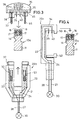
- Fig. 1
- eine Darstellung einer ersten Ausführungsform des Stromschienensystems mit auseinandergenommenem Stromabnehmer, wobei Schlitze an der Oberseite und an der Unterseite der Profilschiene vorhanden sind,
- Fig. 2
- eine zweite Ausführungsform des Stromschienensystems, ebenfalls mit Schlitzen an der Unterseite und an der Oberseite der Profilschiene,
- Fig. 3
- eine dritte Ausführungsform, bei der Schlitze nur an der Oberseite der Profilschiene vorhanden sind,
- Fig. 4
- eine vierte Ausführungsform,
- Fig. 5
- eine modifizierte Ausführungsform von Fig. 1 und
- Fig. 6
- eine modifizierte Ausführungsform von Fig. 3.
Claims (12)
- Hochvolt-Stromschienensystem mit einer Profilschiene (10, 10a), die längslaufende Schlitze (16) aufweist, in denen Stromleiter (17) verlaufen, welche von außen durch Kontaktzungen (26, 40) eines an der Profilschiene aufgehängten Stromabnehmers (20, 20a, 20b, 20c) erreichbar sind,
dadurch gekennzeichnet, dass mindestens einer der Schlitze (16) an der dem Boden abgewandten Oberseite (19) der Profilschiene (10, 10a) angeordnet ist. - Hochvolt-Stromschienensystem nach Anspruch 1, dadurch gekennzeichnet, dass der Stromabnehmer (20, 20a, 20b, 20c) ein auf der Profilschiene (10, 10a) aufliegendes Kopfstück (34) aufweist, von welchem mindestens eine Kontaktzunge (26, 40) nach unten absteht.
- Hochvolt-Stromschienensystem nach Anspruch 1 oder 2, dadurch gekennzeichnet, dass der Stromabnehmer (20, 20a, 20b, 20c) zwei die Profilschiene (10, 10a) zwischen sich einschließende Seitenschenkel (22, 23) aufweist, die an den unteren Enden durch einen Querschenkel (24) und an den oberen Enden durch ein abnehmbares Kopfstück (34) verbunden sind.
- Hochvolt-Stromschienensystem nach Anspruch 2 oder 3, dadurch gekennzeichnet, dass mindestens einer der Seitenschenkel (22, 23) ein Kontaktelement (32, 55) und das Kopfstück (34) ein damit zusammengreifendes Kontaktelement (33, 56) aufweist.
- Hochvolt-Stromschienensystem nach einem der Ansprüche 2 - 4, dadurch gekennzeichnet, dass das Kopfstück (34) eine mit den Seitenschenkeln (22, 23) verbindbare Kappe (35) aufweist, in der ein Schieber (38) federnd gehalten ist, wobei die mindestens eine Kontaktzunge (40) und mindestens ein Kontaktelement (33) an dem Schieber (38) befestigt sind.
- Hochvolt-Stromschienensystem nach einem der Ansprüche 2 - 5, dadurch gekennzeichnet, dass das Kopfstück (34) einen Sicherheitsschalter (45) enthält, der die Kontaktzunge (40) nur dann mit dem zugehörigen Kontaktelement (33) verbindet, wenn das Kopfstück (34) fest mit den Seitenschenkeln (22, 23) verbunden ist.
- Hochvolt-Stromschienensystem nach Anspruch 1 oder 2, dadurch gekennzeichnet, dass der Stromabnehmer (20a, 20c) nur einen Seitenschenkel (22) aufweist, welcher ein Kopfstück (34) mit einem unteren Querschenkel (24) verbindet.
- Hochvolt-Stromschienensystem nach Anspruch 7, dadurch gekennzeichnet, dass der untere Querschenkel (24) ein federnder Verschluss (52) trägt, welcher die Profilschiene (10a) untergreift und den Stromabnehmer (20c) gegen seitliches Verschieben sichert.
- Hochvolt-Stromschienensystem nach einem der Ansprüche 1 - 8, dadurch gekennzeichnet, dass ein Schlitz (16) an der Oberseite (19) und ein weiterer Schlitz (16) an der Unterseite der Profilschiene (10) verläuft.
- Hochvolt-Stromschienensystem nach einem der Ansprüche 1 - 8, dadurch gekennzeichnet, dass zwei Schlitze (16) an der Oberseite der Profilschiene (10a) verlaufen.
- Hochvolt-Stromschienensystem nach einem der Ansprüche 1 - 10, dadurch gekennzeichnet, dass die Profilschiene (10, 10a) einen metallischen Schienenkörper (11) mit mindestens einer längslaufenden Nut (12, 13) aufweist, wobei in der Nut eine Kunststoffleiste (14) enthalten ist, welche den Schlitz (16) bildet und den Stromleiter (17) enthält.
- Hochvolt-Stromschienensystem nach Anspruch 4, dadurch gekennzeichnet, dass das Kontaktelement (33, 56) des Kopfstücks (34) von einer isolierenden Hülse (60, 61) als Berührungsschutz umgeben ist.
Applications Claiming Priority (2)
| Application Number | Priority Date | Filing Date | Title |
|---|---|---|---|
| DE20101581U | 2001-01-31 | ||
| DE20101581U DE20101581U1 (de) | 2001-01-31 | 2001-01-31 | Hochvolt-Stromschienensystem |
Publications (2)
| Publication Number | Publication Date |
|---|---|
| EP1233482A1 true EP1233482A1 (de) | 2002-08-21 |
| EP1233482B1 EP1233482B1 (de) | 2004-04-21 |
Family
ID=7952266
Family Applications (1)
| Application Number | Title | Priority Date | Filing Date |
|---|---|---|---|
| EP02001391A Expired - Lifetime EP1233482B1 (de) | 2001-01-31 | 2002-01-19 | Hochvolt-Stromschienensystem |
Country Status (6)
| Country | Link |
|---|---|
| EP (1) | EP1233482B1 (de) |
| AT (1) | ATE265098T1 (de) |
| DE (2) | DE20101581U1 (de) |
| DK (1) | DK1233482T3 (de) |
| ES (1) | ES2218475T3 (de) |
| TR (1) | TR200401274T4 (de) |
Cited By (1)
| Publication number | Priority date | Publication date | Assignee | Title |
|---|---|---|---|---|
| EP2833490A1 (de) | 2013-07-31 | 2015-02-04 | Cefla Societa' Cooperativa | Stromschiene, insbesondere zur Versorgung von Metallregaleinheiten mit Strom, und Verfahren zu deren Herstellung |
Families Citing this family (1)
| Publication number | Priority date | Publication date | Assignee | Title |
|---|---|---|---|---|
| BE1028162B1 (nl) * | 2020-03-25 | 2021-10-25 | Delta Light Nv | Kit, lichtelement, sensorelement, geleidingsbaan en werkwijze voor bevestiging van een element op een geleidingsbaan |
Citations (6)
| Publication number | Priority date | Publication date | Assignee | Title |
|---|---|---|---|---|
| US4099817A (en) * | 1977-01-27 | 1978-07-11 | Donald J. Booty | Track lighting |
| DE3817133A1 (de) * | 1987-05-20 | 1988-12-01 | Halloform Gmbh & Co Kg | Niedervolt-stromschiene |
| US4812134A (en) * | 1988-05-23 | 1989-03-14 | Miller Ruth E | Wall mounted lighting track system |
| EP0379244A1 (de) * | 1989-01-20 | 1990-07-25 | Janse Lichtreklame B.V. | Beleuchtungssystem für Werkbungszwecke |
| EP0871263A2 (de) * | 1997-04-11 | 1998-10-14 | Andreas Hierzer | Adapter, Stromschiene und Kupplungsvorrichtung |
| EP0924814A2 (de) * | 1997-12-17 | 1999-06-23 | Alcatel | Stromverteilerschiene für Installationszwecke |
Family Cites Families (3)
| Publication number | Priority date | Publication date | Assignee | Title |
|---|---|---|---|---|
| DE2327078A1 (de) * | 1972-05-29 | 1973-12-13 | Staff Kg | Stromverteilerschiene fuer stromabnehmer, insbesondere adapter |
| FR2595443B1 (fr) * | 1986-03-06 | 1989-04-14 | Soleansky Christian | Dispositif pour la suspension et l'eclairage d'objets |
| DE8620925U1 (de) * | 1986-08-04 | 1986-09-18 | Halloform GmbH, 4901 Hiddenhausen | Stromschiene, insbesondere Niederspannungsstromschiene |
-
2001
- 2001-01-31 DE DE20101581U patent/DE20101581U1/de not_active Expired - Lifetime
-
2002
- 2002-01-19 ES ES02001391T patent/ES2218475T3/es not_active Expired - Lifetime
- 2002-01-19 AT AT02001391T patent/ATE265098T1/de active
- 2002-01-19 DE DE50200361T patent/DE50200361D1/de not_active Expired - Lifetime
- 2002-01-19 EP EP02001391A patent/EP1233482B1/de not_active Expired - Lifetime
- 2002-01-19 TR TR2004/01274T patent/TR200401274T4/xx unknown
- 2002-01-19 DK DK02001391T patent/DK1233482T3/da active
Patent Citations (6)
| Publication number | Priority date | Publication date | Assignee | Title |
|---|---|---|---|---|
| US4099817A (en) * | 1977-01-27 | 1978-07-11 | Donald J. Booty | Track lighting |
| DE3817133A1 (de) * | 1987-05-20 | 1988-12-01 | Halloform Gmbh & Co Kg | Niedervolt-stromschiene |
| US4812134A (en) * | 1988-05-23 | 1989-03-14 | Miller Ruth E | Wall mounted lighting track system |
| EP0379244A1 (de) * | 1989-01-20 | 1990-07-25 | Janse Lichtreklame B.V. | Beleuchtungssystem für Werkbungszwecke |
| EP0871263A2 (de) * | 1997-04-11 | 1998-10-14 | Andreas Hierzer | Adapter, Stromschiene und Kupplungsvorrichtung |
| EP0924814A2 (de) * | 1997-12-17 | 1999-06-23 | Alcatel | Stromverteilerschiene für Installationszwecke |
Cited By (1)
| Publication number | Priority date | Publication date | Assignee | Title |
|---|---|---|---|---|
| EP2833490A1 (de) | 2013-07-31 | 2015-02-04 | Cefla Societa' Cooperativa | Stromschiene, insbesondere zur Versorgung von Metallregaleinheiten mit Strom, und Verfahren zu deren Herstellung |
Also Published As
| Publication number | Publication date |
|---|---|
| ATE265098T1 (de) | 2004-05-15 |
| DE50200361D1 (de) | 2004-05-27 |
| ES2218475T3 (es) | 2004-11-16 |
| TR200401274T4 (tr) | 2004-07-21 |
| EP1233482B1 (de) | 2004-04-21 |
| DE20101581U1 (de) | 2002-06-20 |
| DK1233482T3 (da) | 2004-06-01 |
Similar Documents
| Publication | Publication Date | Title |
|---|---|---|
| DE19951789A1 (de) | Anschlussklemme | |
| DE69311591T2 (de) | Anschlussvorrichtung für einen Niederspannungsschalter mit Kunststoffgehäuse | |
| EP0017163B1 (de) | Abdeckung der Anschlüsse von elektrischen Schaltgeräten | |
| EP0075280A2 (de) | Schraubklemme | |
| EP1233482B1 (de) | Hochvolt-Stromschienensystem | |
| DE8206021U1 (de) | Warnanzeigevorrichtung fuer belagverschleiss an bremsbacken | |
| DE202018102794U1 (de) | Verbinder zur stirnseitigen Verbindung von Leuchtentragschienen | |
| EP0762583A2 (de) | Niederspannungs-Sammelschienensystem | |
| DE69302103T2 (de) | Anschlussklemme für eine modulare elektrische Vorrichtung | |
| DE4110251C2 (de) | ||
| EP1868265B1 (de) | Leiteranschluß für eine auf eine Hutschiene aufsetzbare Klemme | |
| EP0451723B1 (de) | Schnellbefestigingsvorrichtung zum Aufschnappen eines Installationsgerätes auf eine Normprofiltragschiene | |
| DE4420072A1 (de) | Vorrichtung zum Anschließen elektrischer Leiter an einen Schaltapparat | |
| DE2629090C2 (de) | Befestigungsvorrichtung mit Verriegelungsfunktion für eine auf einer Tragschiene angeordnete elektrische Baugruppe | |
| DE19817934C1 (de) | Stromeinspeisung für längsgeschlitzte Schleifleitungen | |
| EP1028488B1 (de) | Anschlussklemme für ein elektrisches Installationsgerät | |
| DE7902093U1 (de) | Kontakteinsatz, bestehend aus einer Klemmfeder und einem Kontaktrahmen, insbesondere für Lichtbänder | |
| DE3007970A1 (de) | Elektrische schaltanlage | |
| DE1765056A1 (de) | Anschlussschiene fuer die Versorgung von Verbrauchern mit elektrischem Strom | |
| DE102005047045B3 (de) | Anschlussadapter | |
| DE4011446A9 (de) | Schnellbefestigungsvorrichtung zum Aufschnappen eines Installationsgerätes auf eine Normprofiltragschiene | |
| DE29503158U1 (de) | Elektrisches Bauteil | |
| DE1268249B (de) | Schaltanlagen-Reihenklemme fuer Schutzleiter | |
| DE1168990B (de) | Nulleiter-Trennklemmleiste | |
| DE10053035A1 (de) | Blattfederklemme |
Legal Events
| Date | Code | Title | Description |
|---|---|---|---|
| PUAI | Public reference made under article 153(3) epc to a published international application that has entered the european phase |
Free format text: ORIGINAL CODE: 0009012 |
|
| AK | Designated contracting states |
Kind code of ref document: A1 Designated state(s): AT BE CH CY DE DK ES FI FR GB GR IE IT LI LU MC NL PT SE TR |
|
| AX | Request for extension of the european patent |
Free format text: AL;LT;LV;MK;RO;SI |
|
| 17P | Request for examination filed |
Effective date: 20021210 |
|
| 17Q | First examination report despatched |
Effective date: 20030401 |
|
| AKX | Designation fees paid |
Designated state(s): AT BE CH CY DE DK ES FI FR GB GR IE IT LI LU MC NL PT SE TR |
|
| GRAP | Despatch of communication of intention to grant a patent |
Free format text: ORIGINAL CODE: EPIDOSNIGR1 |
|
| GRAS | Grant fee paid |
Free format text: ORIGINAL CODE: EPIDOSNIGR3 |
|
| GRAA | (expected) grant |
Free format text: ORIGINAL CODE: 0009210 |
|
| AK | Designated contracting states |
Kind code of ref document: B1 Designated state(s): AT BE CH CY DE DK ES FI FR GB GR IE IT LI LU MC NL PT SE TR |
|
| PG25 | Lapsed in a contracting state [announced via postgrant information from national office to epo] |
Ref country code: FI Free format text: LAPSE BECAUSE OF FAILURE TO SUBMIT A TRANSLATION OF THE DESCRIPTION OR TO PAY THE FEE WITHIN THE PRESCRIBED TIME-LIMIT Effective date: 20040421 |
|
| REG | Reference to a national code |
Ref country code: GB Ref legal event code: FG4D Free format text: NOT ENGLISH |
|
| REG | Reference to a national code |
Ref country code: CH Ref legal event code: EP |
|
| RAP2 | Party data changed (patent owner data changed or rights of a patent transferred) |
Owner name: OLIGO LICHTTECHNIK GMBH |
|
| RIN2 | Information on inventor provided after grant (corrected) |
Inventor name: KEFERSTEIN, RALF |
|
| REG | Reference to a national code |
Ref country code: IE Ref legal event code: FG4D Free format text: GERMAN |
|
| REF | Corresponds to: |
Ref document number: 50200361 Country of ref document: DE Date of ref document: 20040527 Kind code of ref document: P |
|
| REG | Reference to a national code |
Ref country code: CH Ref legal event code: NV Representative=s name: ISLER & PEDRAZZINI AG |
|
| REG | Reference to a national code |
Ref country code: DK Ref legal event code: T3 |
|
| NLT2 | Nl: modifications (of names), taken from the european patent patent bulletin |
Owner name: OLIGO LICHTTECHNIK GMBH |
|
| PG25 | Lapsed in a contracting state [announced via postgrant information from national office to epo] |
Ref country code: GR Free format text: LAPSE BECAUSE OF FAILURE TO SUBMIT A TRANSLATION OF THE DESCRIPTION OR TO PAY THE FEE WITHIN THE PRESCRIBED TIME-LIMIT Effective date: 20040721 |
|
| GBT | Gb: translation of ep patent filed (gb section 77(6)(a)/1977) |
Effective date: 20040701 |
|
| REG | Reference to a national code |
Ref country code: SE Ref legal event code: TRGR |
|
| ET | Fr: translation filed | ||
| REG | Reference to a national code |
Ref country code: ES Ref legal event code: FG2A Ref document number: 2218475 Country of ref document: ES Kind code of ref document: T3 |
|
| PG25 | Lapsed in a contracting state [announced via postgrant information from national office to epo] |
Ref country code: LU Free format text: LAPSE BECAUSE OF NON-PAYMENT OF DUE FEES Effective date: 20050119 Ref country code: CY Free format text: LAPSE BECAUSE OF FAILURE TO SUBMIT A TRANSLATION OF THE DESCRIPTION OR TO PAY THE FEE WITHIN THE PRESCRIBED TIME-LIMIT Effective date: 20050119 |
|
| PG25 | Lapsed in a contracting state [announced via postgrant information from national office to epo] |
Ref country code: MC Free format text: LAPSE BECAUSE OF NON-PAYMENT OF DUE FEES Effective date: 20050131 |
|
| PLBE | No opposition filed within time limit |
Free format text: ORIGINAL CODE: 0009261 |
|
| STAA | Information on the status of an ep patent application or granted ep patent |
Free format text: STATUS: NO OPPOSITION FILED WITHIN TIME LIMIT |
|
| 26N | No opposition filed |
Effective date: 20050124 |
|
| REG | Reference to a national code |
Ref country code: CH Ref legal event code: PCAR Free format text: ISLER & PEDRAZZINI AG;POSTFACH 1772;8027 ZUERICH (CH) |
|
| PG25 | Lapsed in a contracting state [announced via postgrant information from national office to epo] |
Ref country code: PT Free format text: LAPSE BECAUSE OF NON-PAYMENT OF DUE FEES Effective date: 20040921 |
|
| REG | Reference to a national code |
Representative=s name: WAGNER ALBIGER & PARTNER PATENTANWAELTE MBB, DE Ref country code: DE Ref legal event code: R082 Ref document number: 50200361 Country of ref document: DE Ref country code: DE Ref legal event code: R082 Ref document number: 50200361 Country of ref document: DE Representative=s name: MUELLER-GERBES WAGNER ALBIGER PATENTANWAELTE, DE |
|
| PGFP | Annual fee paid to national office [announced via postgrant information from national office to epo] |
Ref country code: BE Payment date: 20140122 Year of fee payment: 13 Ref country code: SE Payment date: 20140123 Year of fee payment: 13 Ref country code: IE Payment date: 20140121 Year of fee payment: 13 Ref country code: DK Payment date: 20140127 Year of fee payment: 13 |
|
| PGFP | Annual fee paid to national office [announced via postgrant information from national office to epo] |
Ref country code: FR Payment date: 20140124 Year of fee payment: 13 Ref country code: ES Payment date: 20140122 Year of fee payment: 13 Ref country code: IT Payment date: 20140128 Year of fee payment: 13 Ref country code: TR Payment date: 20140114 Year of fee payment: 13 |
|
| PGFP | Annual fee paid to national office [announced via postgrant information from national office to epo] |
Ref country code: GB Payment date: 20140123 Year of fee payment: 13 |
|
| PG25 | Lapsed in a contracting state [announced via postgrant information from national office to epo] |
Ref country code: BE Free format text: LAPSE BECAUSE OF NON-PAYMENT OF DUE FEES Effective date: 20150131 |
|
| REG | Reference to a national code |
Ref country code: DK Ref legal event code: EBP Effective date: 20150131 |
|
| REG | Reference to a national code |
Ref country code: SE Ref legal event code: EUG |
|
| GBPC | Gb: european patent ceased through non-payment of renewal fee |
Effective date: 20150119 |
|
| PG25 | Lapsed in a contracting state [announced via postgrant information from national office to epo] |
Ref country code: GB Free format text: LAPSE BECAUSE OF NON-PAYMENT OF DUE FEES Effective date: 20150119 |
|
| REG | Reference to a national code |
Ref country code: FR Ref legal event code: ST Effective date: 20150930 |
|
| REG | Reference to a national code |
Ref country code: IE Ref legal event code: MM4A |
|
| PG25 | Lapsed in a contracting state [announced via postgrant information from national office to epo] |
Ref country code: FR Free format text: LAPSE BECAUSE OF NON-PAYMENT OF DUE FEES Effective date: 20150202 Ref country code: SE Free format text: LAPSE BECAUSE OF NON-PAYMENT OF DUE FEES Effective date: 20150120 |
|
| PG25 | Lapsed in a contracting state [announced via postgrant information from national office to epo] |
Ref country code: IT Free format text: LAPSE BECAUSE OF NON-PAYMENT OF DUE FEES Effective date: 20150119 |
|
| PG25 | Lapsed in a contracting state [announced via postgrant information from national office to epo] |
Ref country code: IE Free format text: LAPSE BECAUSE OF NON-PAYMENT OF DUE FEES Effective date: 20150119 Ref country code: DK Free format text: LAPSE BECAUSE OF NON-PAYMENT OF DUE FEES Effective date: 20150131 |
|
| REG | Reference to a national code |
Ref country code: ES Ref legal event code: FD2A Effective date: 20160226 |
|
| PG25 | Lapsed in a contracting state [announced via postgrant information from national office to epo] |
Ref country code: ES Free format text: LAPSE BECAUSE OF NON-PAYMENT OF DUE FEES Effective date: 20150120 |
|
| PG25 | Lapsed in a contracting state [announced via postgrant information from national office to epo] |
Ref country code: TR Free format text: LAPSE BECAUSE OF NON-PAYMENT OF DUE FEES Effective date: 20150119 |
|
| PGFP | Annual fee paid to national office [announced via postgrant information from national office to epo] |
Ref country code: CH Payment date: 20190124 Year of fee payment: 18 Ref country code: NL Payment date: 20190122 Year of fee payment: 18 Ref country code: DE Payment date: 20190227 Year of fee payment: 18 |
|
| PGFP | Annual fee paid to national office [announced via postgrant information from national office to epo] |
Ref country code: AT Payment date: 20190118 Year of fee payment: 18 |
|
| REG | Reference to a national code |
Ref country code: DE Ref legal event code: R082 Ref document number: 50200361 Country of ref document: DE Representative=s name: WAGNER ALBIGER & PARTNER PATENTANWAELTE MBB, DE Ref country code: DE Ref legal event code: R081 Ref document number: 50200361 Country of ref document: DE Owner name: OLIGO LICHTTECHNIK GMBH, DE Free format text: FORMER OWNER: OLIGO LICHTTECHNIK GMBH, 53773 HENNEF, DE |
|
| REG | Reference to a national code |
Ref country code: DE Ref legal event code: R119 Ref document number: 50200361 Country of ref document: DE |
|
| REG | Reference to a national code |
Ref country code: CH Ref legal event code: PL |
|
| REG | Reference to a national code |
Ref country code: NL Ref legal event code: MM Effective date: 20200201 |
|
| REG | Reference to a national code |
Ref country code: AT Ref legal event code: MM01 Ref document number: 265098 Country of ref document: AT Kind code of ref document: T Effective date: 20200119 |
|
| PG25 | Lapsed in a contracting state [announced via postgrant information from national office to epo] |
Ref country code: DE Free format text: LAPSE BECAUSE OF NON-PAYMENT OF DUE FEES Effective date: 20200801 Ref country code: NL Free format text: LAPSE BECAUSE OF NON-PAYMENT OF DUE FEES Effective date: 20200201 |
|
| PG25 | Lapsed in a contracting state [announced via postgrant information from national office to epo] |
Ref country code: CH Free format text: LAPSE BECAUSE OF NON-PAYMENT OF DUE FEES Effective date: 20200131 Ref country code: AT Free format text: LAPSE BECAUSE OF NON-PAYMENT OF DUE FEES Effective date: 20200119 Ref country code: LI Free format text: LAPSE BECAUSE OF NON-PAYMENT OF DUE FEES Effective date: 20200131 |