EP1233232B1 - Beleuchtungseinrichtung - Google Patents
Beleuchtungseinrichtung Download PDFInfo
- Publication number
- EP1233232B1 EP1233232B1 EP01128283A EP01128283A EP1233232B1 EP 1233232 B1 EP1233232 B1 EP 1233232B1 EP 01128283 A EP01128283 A EP 01128283A EP 01128283 A EP01128283 A EP 01128283A EP 1233232 B1 EP1233232 B1 EP 1233232B1
- Authority
- EP
- European Patent Office
- Prior art keywords
- conductor
- lighting device
- contact
- led
- led element
- Prior art date
- Legal status (The legal status is an assumption and is not a legal conclusion. Google has not performed a legal analysis and makes no representation as to the accuracy of the status listed.)
- Expired - Lifetime
Links
Images


Classifications
-
- F—MECHANICAL ENGINEERING; LIGHTING; HEATING; WEAPONS; BLASTING
- F21—LIGHTING
- F21S—NON-PORTABLE LIGHTING DEVICES; SYSTEMS THEREOF; VEHICLE LIGHTING DEVICES SPECIALLY ADAPTED FOR VEHICLE EXTERIORS
- F21S8/00—Lighting devices intended for fixed installation
- F21S8/03—Lighting devices intended for fixed installation of surface-mounted type
- F21S8/032—Lighting devices intended for fixed installation of surface-mounted type the surface being a floor or like ground surface, e.g. pavement
-
- F—MECHANICAL ENGINEERING; LIGHTING; HEATING; WEAPONS; BLASTING
- F21—LIGHTING
- F21S—NON-PORTABLE LIGHTING DEVICES; SYSTEMS THEREOF; VEHICLE LIGHTING DEVICES SPECIALLY ADAPTED FOR VEHICLE EXTERIORS
- F21S4/00—Lighting devices or systems using a string or strip of light sources
- F21S4/20—Lighting devices or systems using a string or strip of light sources with light sources held by or within elongate supports
- F21S4/28—Lighting devices or systems using a string or strip of light sources with light sources held by or within elongate supports rigid, e.g. LED bars
-
- F—MECHANICAL ENGINEERING; LIGHTING; HEATING; WEAPONS; BLASTING
- F21—LIGHTING
- F21V—FUNCTIONAL FEATURES OR DETAILS OF LIGHTING DEVICES OR SYSTEMS THEREOF; STRUCTURAL COMBINATIONS OF LIGHTING DEVICES WITH OTHER ARTICLES, NOT OTHERWISE PROVIDED FOR
- F21V21/00—Supporting, suspending, or attaching arrangements for lighting devices; Hand grips
- F21V21/002—Supporting, suspending, or attaching arrangements for lighting devices; Hand grips making direct electrical contact, e.g. by piercing
-
- F—MECHANICAL ENGINEERING; LIGHTING; HEATING; WEAPONS; BLASTING
- F21—LIGHTING
- F21V—FUNCTIONAL FEATURES OR DETAILS OF LIGHTING DEVICES OR SYSTEMS THEREOF; STRUCTURAL COMBINATIONS OF LIGHTING DEVICES WITH OTHER ARTICLES, NOT OTHERWISE PROVIDED FOR
- F21V5/00—Refractors for light sources
- F21V5/04—Refractors for light sources of lens shape
-
- F—MECHANICAL ENGINEERING; LIGHTING; HEATING; WEAPONS; BLASTING
- F21—LIGHTING
- F21V—FUNCTIONAL FEATURES OR DETAILS OF LIGHTING DEVICES OR SYSTEMS THEREOF; STRUCTURAL COMBINATIONS OF LIGHTING DEVICES WITH OTHER ARTICLES, NOT OTHERWISE PROVIDED FOR
- F21V31/00—Gas-tight or water-tight arrangements
-
- F—MECHANICAL ENGINEERING; LIGHTING; HEATING; WEAPONS; BLASTING
- F21—LIGHTING
- F21Y—INDEXING SCHEME ASSOCIATED WITH SUBCLASSES F21K, F21L, F21S and F21V, RELATING TO THE FORM OR THE KIND OF THE LIGHT SOURCES OR OF THE COLOUR OF THE LIGHT EMITTED
- F21Y2115/00—Light-generating elements of semiconductor light sources
- F21Y2115/10—Light-emitting diodes [LED]
Definitions
- the invention relates to a lighting device with a three-wire conductor strip, which is electrically connected in the axial direction with in series successively arranged LED elements, each LED element of a surrounding the conductor strip in the amount of each LED element, at least partially translucent plastic housing is added.
- the lighting strip has a multi-conductor strip, which is equipped with in series successively arranged LED elements, on, wherein the conductor strip of a plurality of cut to length, lined up in the axial direction Conductor strip sections, wherein in each case between two axially adjacent conductor strip sections arranged with these electrically conductively connected circuit board and wherein each circuit board is equipped with an LED element.
- the individual wires of the conductor strip are wrapped with insulation, that the insulation at the end portions of each conductor strip portion is removed, and that the connection between the respective end of a conductor strip portion and the respective printed circuit board is made via electrically conductive contact elements, wherein between the contact elements and the wires of the conductor strip portion each have a crimped connection and between the contact elements and the conductor tracks of the printed circuit board in each case a riveted connection is provided ,
- the known lighting strip further shows that the end regions of the conductor strip sections, the contact elements, the circuit boards and the LED elements are each encapsulated in a plastic housing which is at least partially translucent and formed by direct encapsulation with a plastic material.
- the invention is based on a lighting device of the type mentioned in the task to simplify these compared to the cited prior art, both in the design and in the production significantly.
- the two-shell design of the plastic housing allows easy insertion of an LED element, an axial conductor strip area and electrical contact means in one of the half shells, the simple establishment of an electrical connection between the LED element and the respective conductors of the conductor strip and a simple closing of the plastic housing by means the lid shell. Since the positive conductor and the negative conductor run through and only the center conductor is formed interrupted, there is a considerable work saving compared to the prior art also with respect to the stripping process.
- the measure according to claim 2 which is preferably provided, allows a pure plug-in mounting of electrically conductive to be interconnected items and thus provides a particularly easy to betechnikstelligende and a particularly cost-effective solution, especially for the production of electrical connections neither a stripping nor use of printed circuit boards or the like is required.
- the measure according to claim 3 is provided for the cases in which special demands should be placed on the quality and reliability.
- a partial stripping is necessary if the measure according to claim 4 use made, but compared to the prior art has the advantage of a direct electrical connection between the conductor strip and the LED elements with the elimination of previously required printed circuit boards.
- the measure according to claim 5 ensures that the resistors still required in the known lighting strip can be omitted, which contributes to the simplification and cheapening of the lighting device according to the invention.
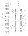
- FIG. 1 shows, in the manner of a circuit diagram, a segment 1 of a lighting device arranged in several segments.
- the lighting device has a three-wire conductor strip 2, which is conductively connected to series-connected LED elements 3, wherein each LED element 3 of a also the conductor strip 2 in the amount of each LED element surrounding, preferably crystal clear plastic housing 4 received is (see also Fig. 1a).
- the segment 1 of FIG. 1 has eight, each in a plastic housing 4 arranged, LED elements 3 (it can also be more or less provided) and a conductor strip 2 with a continuous positive conductor 5, a continuous negative conductor 6 and a, in the embodiment According to Fig. 1 seven-row center conductor 7 as a resistance cable. In a test arrangement, a seven-times series switched center conductor 7 has been designed as a resistance cable with 90.3 ohms per segment 1, proved to be particularly useful.
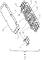
- the or each plastic housing 4 has a two-shell design with a first shell 9 and a second shell 10.
- the first shell 9 forms the upper housing shell
- the second shell 10 forms the lower housing shell.
- the shells 9 and 10, which are fixed to each other via Klipsetti 8, have complementary semicircular shots 11 for receiving the continuous positive conductor 5, the continuous negative conductor 6 and interrupted in the region of each plastic housing 4 center conductor 7 and a circumferential receiving groove for a too Sealant having adhesive (not shown) on.
- the procedure may be as follows:
- the upper shells (first shells 9) of possibly two segments 1 are received by an elongated, not shown, apparatus table.
- the continuous positive conductor 5 and negative conductor 6 are stripped in the necessary areas and continuously clamped in the receptacles 11 of the first Trays 9 inserted.
- the center conductor 7 is stripped to length and also inserted into the associated receptacles 11.
- the LED elements 3 are inserted into the recesses 13. Alsdann then the electrical connection by applying a contact adhesive and by activating the contact adhesive z. B. in a heating furnace or by local heaters.
- the lower shells (second shells 10) are placed on the upper shells and clipped with these.
- the so far completed on the device table lighting device can now be sealed with a sliding Kleberdosierstrom, with the seal refers to the plastic housing 4 and to the sealing and permanent fixing of their shells 9 and 10 to each other.
- the second shells 10 may each be provided with an adhesive feed opening, not shown, and possibly also with a respective not shown vent opening.
- the first shell 9 forms the housing upper shell, which is formed with the integrally formed material integrally with the lens 14 and the second shell 10, the housing lower shell.
- the shell 9 are receptacles 11 for the conductors 5-7, a recess 13 for an LED element 3, possibly a circumferential receiving groove for a not shown sealing / adhesive and free spaces for the arrangement of metallic contact elements 17 provided by corresponding recordings and the like.
- the second shell 10 are supplemented.
- the electrical contact elements 17 are z. B. made of tinned copper sheet and designed so that they come into contact with one each with an LED element 3 and the other with the positive conductor 5 (or negative conductor 6) and the center conductor 7 in contact.
- the metallic contact elements 17 have upwardly angled material tabs 18 with recesses 19 accessible from above, wherein the recessed edges act as cutting edges for cutting through the core 16 surrounding insulation of the positive conductor 5, the negative conductor 6 and the center conductor 7 are formed. It is understood that the opening width of the recesses 19 is to be matched to the respective Porterdruchmesser that a secure cutting and secure contact of the respective conductor core 16 is ensured.
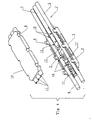
- Fig. 3 shows the clam shell plastic housing 4 without the ladder 5-7, while in Fig. 4, the plastic housing 4 with the conductors 5-7 is equipped.
- 5 shows the arrangement of the new illumination device in the receiving channel 20 of a profile strip 21, which may be an escape route marking, orientation, decoration, or the like. Profile strip 21.
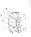
- FIG. 6 A peculiarity of the new lighting device of independent inventive significance is shown in Fig. 6 on a substantially enlarged scale training and design of the already mentioned lens 14.
- This has a flattened head surface 22, which has a radius 23 in a cone 24 passes, whose lower end coincides with the top surface of the shell 10 of the plastic housing 4.
- Outer support of the LED element 3, the lens 14 has a cylindrical recess 25 with a rounded transition to the recess bottom.
- the cone angle is based on the vertical 30 °.
- the design of the lens 14 was carried out using the law of refraction and taking into account the material constant of the material used for the production of the lens 14.
- the lines 26 indicate a beam angle of 120 °, while the lines 27 illustrate a beam angle of 180 °, because the penetrating into the lens 14 rays at point 28 undergo a corresponding change in direction.
- lens 14 is shown as an integral part of a housing shell, it is of course within the scope of the invention to provide a separately manufactured lens 14 for each LED element 3. It is also conceivable, LED elements 3 with arranged from home on it, the LEDs in the manner shown bridging lenses 14 apply.
- the invention is not limited to the illustrated embodiments, but also includes all the same in the context of the invention embodiments. Furthermore, the invention is not limited to the feature combination defined in claim 1, but may also be defined by any other combination of particular features of all individually disclosed individual features. This means that in principle each individual feature of claim 1 can be omitted or replaced by at least one individual feature disclosed elsewhere in the application documents. The present claim 1 is thus to be understood as a first formulation attempt for the identification of the invention.
Landscapes
- Engineering & Computer Science (AREA)
- General Engineering & Computer Science (AREA)
- Arrangement Of Elements, Cooling, Sealing, Or The Like Of Lighting Devices (AREA)
- Led Device Packages (AREA)
- Vehicle Body Suspensions (AREA)
- Polarising Elements (AREA)
- Seal Device For Vehicle (AREA)
- Non-Portable Lighting Devices Or Systems Thereof (AREA)
- Fastening Of Light Sources Or Lamp Holders (AREA)
Description
- Die Erfindung bezieht sich auf eine Beleuchtungseinrichtung mit einem dreiadrigen Leiterstreifen, der in axialer Richtung mit in Reihe hintereinander angeordneten LED-Elementen elektrisch leitend verbunden ist, wobei jedes LED-Element von einem auch den Leiterstreifen in Höhe eines jeden LED-Elements umgebenden, zumindest bereichsweise lichtdurchlässigen Kunststoffgehäuse aufgenommen ist.
- Die DE 196 27 856 A1 zeigt eine Beleuchtungsleiste mit einer Beleuchtungseinrichtung der gattungsgemäßen Art. die Beleuchtungsleiste weist einen mehradrigen Leiterstreifen, der mit in Reihe hintereinander angeordneten LED-Elementen bestückt ist, auf, wobei der Leiterstreifen aus einer Vielzahl von abgelängten, in axialer Richtung aneinandergereihten Leiterstreifenabschnitten besteht, wobei jeweils zwischen zwei axial aneinandergrenzenden Leiterstreifenabschnitten eine mit diesen elektrisch leitend verbundene Leiterplatte angeordnet ist und wobei jede Leiterplatte mit einem LED-Element bestückt ist. Bei der bekannten Beleuchtungsleiste ist weiterhin gezeigt, dass die einzelnen Adern des Leiterstreifens mit einer Isolierung umhüllt sind, dass die Isolierung an den Endbereichen jedes Leiterstreifenabschnitts entfernt ist, und dass die Verbindung zwischen dem jeweiligen Ende eines Leiterstreifenabschnitts und der jeweiligen Leiterplatte über elektrisch leitende Kontaktelemente hergestellt ist, wobei zwischen den Kontaktelementen und den Adern des Leiterstreifenabschnitts jeweils eine Crimpverbindung und zwischen den Kontaktelementen und den Leiterbahnen der Leiterplatte jeweils eine Nietverbindung vorgesehen ist. Die bekannte Beleuchtungsleiste zeigt weiterhin, dass die Endbereiche der Leiterstreifenabschnitte, die Kontaktelemente, die Leiterplatten und die LED-Elemente jeweils in einem zumindest bereichsweise lichtdurchlässigen und durch unmittelbares Umspritzen mit einem Kunststoffmaterial gebildetes Kunststoffgehäuse eingekapselt sind.
- Der Erfindung liegt ausgehend von einer Beleuchtungseinrichtung der eingangs genannten Art die Aufgabe zugrunde, diese gegenüber dem aufgezeigten Stand der Technik sowohl in der Ausgestaltung als auch in der Herstellung wesentlich zu vereinfachen.
- Erfindungsgemäß wird diese Aufgabe mit den im Anspruch 1 angegebenen Merkmalen gelöst, während in den Unteransprüchen vorteilhafte Weiterbildungen und zweckmäßige Ausgestaltungen der Erfindung gekennzeichnet sind.
- Die zweischalige Ausbildung des Kunststoffgehäuses ermöglicht ein einfaches Einlegen eines LED-Elements, eines axialen Leiterstreifenbereichs und elektrischer Kontaktmittel in eine der Halbschalen, die einfache Herstellung einer elektrischen Verbindung zwischen dem LED-Element und den jeweils benötigen Leitern des Leiterstreifens und ein einfaches Verschließen des Kunststoffgehäuses mittels der Deckelschale. Da der Plusleiter und der Minusleiter durchlaufen und nur der Mittelleiter unterbrochen ausgebildet ist, ergibt sich gegenüber dem Stand der Technik eine beachtliche Arbeitseinsparung auch in bezug auf den Abisoliervorgang.
- Die Maßnahme nach Anspruch 2, die bevorzugt vorgesehen ist, erlaubt eine reine Steckmontage der elektrisch leitend miteinander zu verbindenden Einzelteile und stellt damit eine besonders einfach zu bewerkstelligende und eine besonders kostengünstige Lösung dar, zumal für die Herstellung der elektrischen Verbindungen weder ein Abisoliervorgang noch ein Einsatz von Leiterplatten oder dgl. erforderlich ist.
- Die Maßnahme nach Anspruch 3 ist für die Fälle vorgesehen, bei denen besondere Anforderungen an die Qualität und Funktionssicherheit gestellt werden sollten.
- Eine bereichsweise Abisolierung ist nötig, wenn von der Maßnahme nach Anspruch 4 Gebrauch gemacht wird, die aber gegenüber dem Stand der Technik den Vorteil einer direkten elektrischen Verbindung zwischen dem Leiterstreifen und den LED-Elementen unter Fortfall von bisher erforderlichen Leiterplatten bietet.
- Durch die Maßnahme nach Anspruch 5 wird erreicht, dass die bei der bekannten Beleuchtungsleiste noch benötigten Widerstände entfallen können, was zur Vereinfachung und Verbilligung der erfindungsgemäßen Beleuchtungseinrichtung beiträgt.
- Weitere besonders zweckmäßige Ausbildungen und Gestaltungsmerkmale der Erfindung sind in den Ansprüchen 6 bis 13 angegeben. Dabei kommt den Maßnahmen nach den Ansprüchen 11 und 12 insofern eine besondere Bedeutung zu, als sich hierdurch die Forderungen der IMO (Internationale Maritime Organisation, eine Unterorganisation der UNO) für Fluchtwegemarkierungen auf Passagierschiffen, optimal erfüllen lassen, wobei zu bemerken ist, dass der Erfindungsgegenstand gemäß Anspruch 11 oder insbesondere 12 auch für diesen Einsatzfall vorgesehen ist.
- Ausführungsbeispiele der Erfindung werden nachfolgend anhand der Zeichnungen näher erläutert, und es zeigen:
- Fig. 1
- einen Schaltplan bzw. ein mit acht LED-Elementen bestücktes Segment der Beleuchtungseinrichtung (vgl. auch Fig. 1a),
- Fig. 2
- ein einzelnes zweischaliges Kunststoffgehäuse eines Segments nach Fig. 1, 1a mit einem in einer Gehäuseschale angeordneten LED-Element und einem Leiterstreifen,
- Fig. 3
- ein zweischaliges Kunststoffgehäuse in einer mit metallischen Kontaktelementen bestückten Ausführungsform ohne Leiterstreifen,
- Fig. 4
- das Kunststoffgehäuse nach Fig. 3 mit Leiterstreifen,
- Fig. 5
- das Kunststoffgehäuse nach Fig. 3 und 4 mit Leiterstreifen, der zu einem benachbarten von einer Profilleiste aufgenommenen Kunststoffgehäuse weitergeführt ist und
- Fig. 6
- einen Schnitt V - V nach Fig. 5.
- Fig. 1 zeigt nach Art eines Schaltplans ein Segment 1 einer aus mehreren Segmenten aneinandergereihten Beleuchtungseinrichtung. Die Beleuchtungseinrichtung weist einen dreiadrigen Leiterstreifen 2 auf, der mit in Reihe hintereinander angeordneten LED-Elementen 3 leitend verbunden ist, wobei jedes LED-Element 3 von einem auch den Leiterstreifen 2 in Höhe eines jeden LED-Elements umgebenden, vorzugsweise glasklar ausgebildeten Kunststoffgehäuse 4 aufgenommen ist (vgl. auch Fig. 1a).
- Das Segment 1 nach Fig. 1 verfügt über acht, jeweils in einem Kunststoffgehäuse 4 angeordnete, LED-Elemente 3 (es können auch mehr oder weniger vorgesehen sein) und über einen Leiterstreifen 2 mit einem durchlaufenden Plusleiter 5, einem durchlaufenden Minusleiter 6 und einem, beim Ausführungsbeispiel nach Fig. 1 siebenmal reihengeschalteten Mittelleiter 7 als Widerstandskabel. Bei einer Versuchsanordnung hat sich ein siebenmal reihengeschalteter Mittelleiter 7 als Widerstandskabel mit 90,3 Ohm pro Segment 1 ausgelegt, als besonders zweckmäßig erwiesen.
- Wie aus Fig. 2 ersichtlich ist, weist das bzw. jedes Kunststoffgehäuse 4 eine zweischalige Ausbildung mit einer ersten Schale 9 und einer zweiten Schale 10 auf. Im Ausführungsbeispiel nach Fig. 2 bildet die erste Schale 9 die Gehäuseoberschale und die zweite Schale 10 die Gehäuseunterschale. Die Schalen 9 und 10, die über Klipselemente 8 aneinander festlegbar sind, weisen sich ergänzende halbrund gestaltete Aufnahmen 11 für die Aufnahme des durchlaufenden Plusleiters 5, des durchlaufenden Minusleiters 6 und des im Bereich jedes Kunststoffgehäuses 4 unterbrochenen Mittelleiters 7 sowie eine umlaufende Aufnahmenut für ein auch Dichtungseigenschaften aufweisenden Klebemittels (nicht gezeigt) auf.
- In einer Ausnehmung 13 der ersten Schale 9, die in einer z. B. in Fig. 5 gezeigten Linse 14 einmündet, sitzt ein darin eingestecktes LED-Element 3. Zur Herstellung einer elektrischen Verbindung zwischen dem LED-Element 3, dem Plusleiter 5 (oder dem Minusleiter 6) und dem Mittelleiter 7 dient hier ein nicht dargestelltes Mittel, vorzugsweise in Form eines Kontaktklebers für dessen Aufnahme eine Verbindungs- bzw. Verteilernut 15 in der Schale 9 vorgesehen ist. Die Verteilernut 15 endet jeweils an abisolierten, den jeweiligen Kern 16 freilegenden Bereichen der Leiter 5 - 7.
- Bei der Fertigung einer Beleuchtungseinrichtung mit Kunststoffgehäusen 4 und Verbindungsmittel nach Fig. 2 kann etwa wie folgt vorgegangen werden: Die Oberschalen (erste Schalen 9) von möglichst zwei Segmenten 1, werden von einem länglichen, nicht gezeigten Vorrichtungstisch aufgenommen. Die durchgängigen Plusleiter 5 und Minusleiter 6 werden in den notwendigen Bereichen abisoliert und durchgängig gespannt in die Aufnahmen 11 der ersten Schalen 9 eingelegt. Der Mittelleiter 7 wird auf Länge abisoliert und ebenfalls in die zugehörigen Aufnahmen 11 eingelegt. Eingelegt werden auch die LED-Elemente 3 in die Ausnehmungen 13. Alsdann erfolgt die elektrische Verbindung durch Applikation eines Kontaktklebers und durch Aktivieren des Kontaktklebers z. B. in einem Wärmeofen oder durch örtliche Heizgeräte. Die Unterschalen (zweite Schalen 10) werden auf die Oberschalen aufgesetzt und mit diesen verklipst. Die soweit auf dem Vorrichtungstisch fertiggestellte Beleuchtungseinrichtung kann nun mit einer verschiebbaren Kleberdosieranlage abgedichtet werden, wobei sich die Abdichtung auf die Kunststoffgehäuse 4 bzw. auf die Abdichtung und dauerhafte Festlegung von deren Schalen 9 und 10 aneinander bezieht. Für die Zuführung des Klebers können die zweiten Schalen 10 mit jeweils einer nicht gezeigten Kleberzuführöffnung und ggf. auch mit jeweils einer nicht gezeigten Entlüftungsöffnung versehen sein.
- Beim Ausführungsbeispiel gemäß Fig. 3, 4 und 5 bildet die erste Schale 9 die Gehäuseoberschale welche mit der einstückig und materialeinheitlich angeformten Linse 14 ausgebildet ist und die zweite Schale 10 die Gehäuseunterschale. In der Schale 9 sind Aufnahmen 11 für die Leiter 5 - 7, eine Ausnehmung 13 für ein LED-Element 3, ggf. eine umlaufende Aufnahmenut für ein nicht gezeigtes Dicht-/Klebemittel und Freiräume für die Anordnung von metallischen Kontaktelementen 17 vorgesehen, die durch entsprechende Aufnahmen und dgl. in der zweiten Schale 10 ergänzt werden.
- Die elektrischen Kontaktelemente 17 sind z. B. aus verzinntem Kupferblech gebildet und so gestaltet, dass sie zum einen jeweils mit einem LED-Element 3 und zum anderen mit dem Plusleiter 5 (oder Minusleiter 6) und dem Mittelleiter 7 in Kontaktberührung kommen. Die metallischen Kontaktelemente 17 weisen nach oben abgewinkelte Materiallappen 18 mit von oben her zugänglichen Ausnehmungen 19 auf, wobei die Ausnehmungsränder als Schneiden zum Durchtrennen der den Kern 16 umgebenden Isolierung der Plusleiter 5, der Minusleiter 6 und der Mittelleiter 7 ausgebildet sind. Es versteht sich, dass die Öffnungsweite der Ausnehmungen 19 derart auf den jeweiligen Leiterdruchmesser abzustimmen ist, dass ein sicheres Durchtrennen und eine sichere Kontaktierung des jeweiligen Leiterkerns 16 gewährleistet ist.
- Bei der Fertigung einer Beleuchtungseinrichtung mit Kunststoffgehäusen 4 nach Fig. 3 und 4 kann etwa wie folgt vorgegangen werden: In die Oberschalen 9 werden die Kontaktelemente 17 eingeklipst und auf diese die LED-Elemente 3 gesetzt und geklemmt, wodurch sich eine zuverlässige elektrische Verbindung zwischen den Kontaktelementen 17 und den Kontakten der LED-Elemente 3 einstellt. Alsdann werden die Oberschalen (erste Schale 9) von möglichst zwei Segmenten 1 von einem nicht gezeigten länglichen Vorrichtungstisch aufgenommen und in diese werden der Plusleiter 5 und der Minusleiter 6 durchgängig gespannt eingelegt und in die mit Schneiden versehenen Ausnehmungen 19 der Kontaktelemente 17 eingedrückt. Eine Abisolierung der Leiter 5 - 7 ist weder vorgesehen noch erforderlich. Die sich daran anschließenden Montageschritte (Aufklipsen der Unterschale 10, Abdichtung und Verklebung sowie ggf. Funktionslichtprüfung) entsprechen der Erläuterung zu Fig. 2.
- Fig. 3 zeigt das zweischalige Kunststoffgehäuse 4 ohne die Leiter 5 - 7, während in Fig. 4 das Kunststoffgehäuse 4 mit den Leitern 5 - 7 bestückt ist. Fig. 5 lässt die Anordnung der neuen Beleuchtungseinrichtung im Aufnahmekanal 20 einer Profilleiste 21 erkennen, bei der es sich um eine Fluchtwegemarkierungs-, Orientierungs-, Dekorations-, oder dgl. Profilleiste 21 handeln kann.
- Eine Besonderheit der neuen Beleuchtungseinrichtung von eigenständiger erfinderischer Bedeutung ist die in Fig. 6 im wesentlich vergrößerten Maßstab gezeigte Ausbildung und Gestaltung der schon erwähnten Linse 14. Diese weist eine abgeplattete Kopffläche 22 auf, die über einen Radius 23 in einen Konus 24 übergeht, dessen unteres Ende mit der Kopffläche der Schale 10 des Kunststoffgehäuses 4 zusammenfällt. Oberhalt des LED-Elements 3 weist die Linse 14 eine zylindrische Ausnehmung 25 mit einem abgerundeten Übergang zum Ausnehmungsboden auf. Der Konuswinkel beträgt auf die Senkrechte bezogen 30°. Die Gestaltung der Linse 14 erfolgte unter Nutzung des Brechnungsgesetzes und unter Beachtung der Materialkonstante des für die Herstellung der Linse 14 verwendeten Werkstoffs. Damit konnte gegenüber einer Lichtverteilung mit einem bisher üblichen Abstrahlwinkel von 120° eine Lichtverteilung mit einem Abstrahlwinkel von 180° erzielt werden. Die Linien 26 geben einen Abstrahlwinkel von 120° an, während die Linien 27 einen Abstrahlwinkel von 180° verdeutlichen, weil die in die Linse 14 eindringenden Strahlen im Punkt 28 eine entsprechende Richtungsänderung erfahren.
- Während in den Zeichnungen die Linse 14 als integrierter Bestandteil einer Gehäuseschale gezeigt ist, liegt es selbstverständlich im Rahmen der Erfindung, für jedes LED-Element 3 eine separat gefertigte Linse 14 vorzusehen. Es ist auch denkbar, LED-Elemente 3 mit von Hause aus daran angeordneten, die Leuchtdioden in gezeigter Weise überbrückenden, Linsen 14 anzuwenden.
- Die Erfindung ist nicht auf die dargestellten Ausführungsbeispiele beschränkt, sondern umfasst auch alle im Sinne der Erfindung gleichwirkenden Ausführungen. Ferner ist die Erfindung nicht auf die im Anspruch 1 definierte Merkmalskombination beschränkt, sondern kann auch durch jede beliebige andere Kombination von bestimmten Merkmalen aller insgesamt offenbarten Einzelmerkmalen definiert sein. Dies bedeutet, dass grundsätzlich jedes Einzelmerkmal des Anspruchs 1 weggelassen bzw. durch mindestens ein an anderer Stelle der Anmeldungsunterlagen offenbartes Einzelmerkmal ersetzt werden kann. Der vorliegende Anspruch 1 ist somit als ein erster Formulierungsversuch für die Kennzeichnung der Erfindung zu verstehen.
Claims (13)
- Beleuchtungseinrichtung mit einem dreiadrigen Leiterstreifen (2), der in axialer Richtung mit in Reihe hintereinander angeordneten LED-Elementen (3) elektrisch leitend verbunden ist, wobei jeweils jedes LED-Element (3) von einem auch den Leiterstreifen (2) in Höhe eines jeden LED-Elements (3) umgebenden, zumindest bereichsweise lichtdurchlässigen Kunststoffgehäuse (4) aufgenommen ist, dadurch gekennzeichnet, dass jedes Kunststoffgehäuse (4) aus zwei Schalen (9, 10) besteht, von denen die eine als Aufnahmeschale für die Aufnahme eines LED-Elements (3), eines axialen Leiterstreifenbereichs und elektrisch leitender Kontaktmittel und die andere Schale als Deckelschale vorgesehen ist, die unter Einschluss von Dichtmittel an der ersten Schale festgelegt ist, und dass der dreiadrige Leiterstreifen (2) einen durchlaufenden Plusleiter (5), einen durchlaufenden Minusleiter (6) und einen unterbrochenen, sich von LED-Element (3) zu LED-Element (3) erstreckenden Mittelleiter (7) umfasst.
- Beleuchtungseinrichtung nach Anspruch 1, dadurch gekennzeichnet, daß als elektrisch leitende Kontaktmittel zwischen den Leiterstreifen (2) und den LED-Elementen (3) metallische Kontaktelemente (17) vorgesehen sind, über die jeweils die elektrische Kontaktierung erfolgt, wobei die metallischen Kontaktelemente (17), die durch bloße Steckmontage mit den LED-Elementen (3) verbunden sind, Schneiden aufweisen, die die Leiterstreifenisolierungen durchdringen und die jeweiligen Leiterkerne (16) kontaktieren.
- Beleuchtungseinrichtung Anspruch 1, dadurch gekennzeichnet, dass als elektrisch leitende Kontaktmittel zwischen dem Leiterstreifen (2) und den LED-Elementen (3) wärmeaktivierbare Lötpasten, Kontaktkleber oder dgl. und metallische Kontaktelemente (17) vorgesehen sind, über die jeweils die elektrische Kontaktierung erfolgt, wobei die metallischen Kontaktelemente (17), die über die Lötpasten, Kontaktkleber oder dgl. mit den LED-Elementen (3) verbunden sind, Schneiden aufweisen, die die Leiterstreifenisolierungen durchdringen und die jeweiligen Leiterkerne (16) kontaktieren.
- Beleuchtungseinrichtung nach Anspruch 1, dadurch gekennzeichnet, dass als elektrisch leitende Kontaktmittel zwischen dem Leiterstreifen (2), der bereichsweise abisoliert ist und den LED-Elementen (3) wärmeaktivierbare Lötpasten, Kontaktkleber oder dgl. vorgesehen sind, über die die elektrische Kontaktierung erfolgt.
- Beleuchtungseinrichtung nach wenigstens einem der vorangegangenen Ansprüche, dadurch gekennzeichnet, dass der Mittelleiter (7) als Widerstandsleiter ausgelegt ist.
- Beleuchtungseinrichtung nach wenigstens einem der vorangegangenen Ansprüche, dadurch gekennzeichnet, dass die Schalen (9, 10) des Kunststoffgehäuses (4) über angeformte Klipselemente aneinanderfestgelegt sind.
- Beleuchtungseinrichtung nach wenigstens einem der vorangegangenen Ansprüche, dadurch gekennzeichnet, dass die Schalen (9, 10) des Kunststoffgehäuses (4) jeweils mit sich ergänzenden Aufnahmen (11) für die einzelnen Leiter (5, 6, 7) des Leiterstreifens (2), ein LED-Element (3), die Metallkontaktelemente (17) und für das zum Abdichten und dauerhafte Verbinden der Schalen (9, 10) vorgesehene Dichtmittel ausgebildet sind.
- Beleuchtungseinrichtung nach Anspruch 3 dadurch gekennzeichnet, dass die Schalen (9, 10) des Kunststoffgehäuses (4) mit Aufnahmen für die Lötpaste und/oder den Kontaktkleber ausgebildet sind.
- Beleuchtungseinrichtung nach wenigstens einem der vorangegangenen Ansprüche, dadurch gekennzeichnet, dass die Schalen (9, 10) des Kunststoffgehäuses (4) als Spritzgußteile aus PC (Polycarbonat) glasklar ausgebildet sind.
- Beleuchtungseinrichtung nach wenigstens einem der vorangegangenen Ansprüche, dadurch gekennzeichnet, dass eine Schale (9, 10) des Kunststoffgehäuses (4) mit einer ein LED-Element (3) überbrückenden Linse (14) ausgebildet ist.
- Beleuchtungseinrichtung nach Anspruch 10, dadurch gekennzeichnet, dass die Linse (14) eine Formgebung zur Lichtverteilung mit einem Abstrahlwinkel größer als 120° aufweist.
- Beleuchtungseinrichtung nach Anspruch 10 oder 11, dadurch gekennzeichnet, dass die Linse (14) eine Formgebung zur Lichtverteilung mit einem Abstrahlwinkel von 180 ° aufweist.
- Beleuchtungseinrichtung nach wenigstens einem der vorangegangenen Ansprüche, dadurch gekennzeichnet, daß dieselbe in einem Aufnahmekanal (20) einer Fluchtwegemarkierungs-, Orientierungs-, Dekorations- oder dgl. Profilleiste (21) angeordnet ist.
Applications Claiming Priority (2)
| Application Number | Priority Date | Filing Date | Title |
|---|---|---|---|
| DE10106961A DE10106961A1 (de) | 2001-02-15 | 2001-02-15 | Bleuchtungseinrichtung |
| DE10106961 | 2001-02-15 |
Publications (3)
| Publication Number | Publication Date |
|---|---|
| EP1233232A2 EP1233232A2 (de) | 2002-08-21 |
| EP1233232A3 EP1233232A3 (de) | 2005-01-19 |
| EP1233232B1 true EP1233232B1 (de) | 2006-06-14 |
Family
ID=7674086
Family Applications (1)
| Application Number | Title | Priority Date | Filing Date |
|---|---|---|---|
| EP01128283A Expired - Lifetime EP1233232B1 (de) | 2001-02-15 | 2001-11-29 | Beleuchtungseinrichtung |
Country Status (9)
| Country | Link |
|---|---|
| US (1) | US6837598B2 (de) |
| EP (1) | EP1233232B1 (de) |
| KR (1) | KR20020067417A (de) |
| AT (1) | ATE330169T1 (de) |
| DE (2) | DE10106961A1 (de) |
| ES (1) | ES2263542T3 (de) |
| HU (1) | HU225335B1 (de) |
| SG (1) | SG114525A1 (de) |
| TW (1) | TWI224181B (de) |
Families Citing this family (59)
| Publication number | Priority date | Publication date | Assignee | Title |
|---|---|---|---|---|
| US7331681B2 (en) * | 2001-09-07 | 2008-02-19 | Litepanels Llc | Lighting apparatus with adjustable lenses or filters |
| US7604361B2 (en) | 2001-09-07 | 2009-10-20 | Litepanels Llc | Versatile lighting apparatus and associated kit |
| US6749310B2 (en) * | 2001-09-07 | 2004-06-15 | Contrast Lighting Services, Inc. | Wide area lighting effects system |
| CN100473891C (zh) * | 2002-06-20 | 2009-04-01 | 永备电池有限公司 | 发光二极管照明装置 |
| DE20300976U1 (de) | 2003-01-17 | 2003-04-03 | Brandau, Jonas, 10407 Berlin | Niederspannungsdekorationsleuchte mit weißen SMD-LEDs |
| DE102004004777B4 (de) * | 2004-01-30 | 2013-08-29 | Osram Opto Semiconductors Gmbh | Verformbares Beleuchtungsmodul |
| US7150647B2 (en) * | 2004-02-03 | 2006-12-19 | Willis Electric Co., Ltd. | In-line socket device and its fabricating method |
| US7144139B2 (en) * | 2004-03-10 | 2006-12-05 | Kramer Eric W | Flexible surface lighting system |
| US20050201068A1 (en) * | 2004-03-10 | 2005-09-15 | Kramer Eric W. | Replaceable LED module |
| ITMI20040756A1 (it) * | 2004-04-16 | 2004-07-16 | Vlm Spa | Sistema di illuminazione modulare comprendente moduli di illuminazione a led ad alta potenza |
| US8911119B1 (en) * | 2004-10-05 | 2014-12-16 | Steven M. Colby | Bulb including cover |
| US11320129B1 (en) | 2004-10-05 | 2022-05-03 | Steven Michael Colby | LED bulb including pulse generator and/or AC/DC converter |
| US9874332B1 (en) | 2013-01-15 | 2018-01-23 | Steven Michael Colby | Bulb including removable cover |
| DE102004062469A1 (de) * | 2004-12-20 | 2006-07-06 | Kabelschlepp Gmbh | Flachkabel und Energieführungskette mit Flachkabel |
| PT3770980T (pt) * | 2005-05-20 | 2024-09-24 | Signify Holding Bv | Módulo emissor de luz |
| US7160140B1 (en) * | 2005-07-13 | 2007-01-09 | Gelcore Llc | LED string light engine |
| US7520771B2 (en) | 2005-07-13 | 2009-04-21 | Lumination Llc | LED string light engine and devices that are illuminated by the string light engine |
| JP4757756B2 (ja) * | 2005-11-14 | 2011-08-24 | Necライティング株式会社 | Ledランプ |
| US8465175B2 (en) | 2005-11-29 | 2013-06-18 | GE Lighting Solutions, LLC | LED lighting assemblies with thermal overmolding |
| DE102006018668B4 (de) * | 2006-04-21 | 2013-04-11 | Osram Gmbh | Modulares Beleuchtungssystem und Beleuchtungsanordnung |
| US20080137377A1 (en) * | 2006-12-11 | 2008-06-12 | Gelcore, Llc | Led light engine and method of manufacturing |
| US7600896B2 (en) * | 2007-07-27 | 2009-10-13 | Baoliang Wang | Outer case of LED module |
| US7854616B2 (en) | 2007-10-12 | 2010-12-21 | The L.D. Kichler Co. | Positionable lighting systems and methods |
| US8599108B2 (en) * | 2007-12-11 | 2013-12-03 | Adti Media, Llc140 | Large scale LED display |
| US8648774B2 (en) | 2007-12-11 | 2014-02-11 | Advance Display Technologies, Inc. | Large scale LED display |
| CA2710110C (en) | 2007-12-21 | 2016-05-17 | Earl J. Hayes | Low profile flexible cable lighting assemblies and methods of making same |
| US20110310601A1 (en) * | 2008-02-15 | 2011-12-22 | Shu-Fa Shao | Light-emitting diode line lamp |
| JP4794587B2 (ja) * | 2008-02-19 | 2011-10-19 | シャープ株式会社 | 光源ユニット、照明装置及び表示装置 |
| US7832896B2 (en) * | 2008-04-18 | 2010-11-16 | Lumination Llc | LED light engine |
| KR200449520Y1 (ko) * | 2008-06-16 | 2010-07-15 | 주식회사 유비젼 | 플렉시블 led 램프를 갖는 가로등의 고정장치 |
| US20100014288A1 (en) * | 2008-07-15 | 2010-01-21 | Presence From Innovation, Llc | Retro-fit light stick device and secondary light source or other electrical device for use with walk-in type coolers and other product display units |
| DE102008055790B4 (de) * | 2008-11-04 | 2010-08-19 | Gernot Schneider | Schutzleiste |
| US7926978B2 (en) * | 2008-12-18 | 2011-04-19 | Kenneth Tsai | Light set with surface mounted light emitting components |
| US8397381B2 (en) * | 2009-08-06 | 2013-03-19 | Allied Bright Technology Limited | Method for manufacturing light set with surface mounted light emitting components |
| US9303861B2 (en) * | 2009-09-14 | 2016-04-05 | Us Vaopto, Inc. | Light emitting diode light source modules |
| US20110075413A1 (en) * | 2009-09-30 | 2011-03-31 | Smith Gregory S | Lighting system |
| US8342733B2 (en) * | 2009-12-14 | 2013-01-01 | Tyco Electronics Corporation | LED lighting assemblies |
| US8474998B2 (en) | 2010-03-08 | 2013-07-02 | Ge Lighting Solutions Llc | Rail and clip mounting for LED modules for fluorescent application replacement |
| DE102011003608A1 (de) * | 2010-08-20 | 2012-02-23 | Tridonic Gmbh & Co. Kg | Gehäustes LED-Modul |
| DK177534B1 (en) | 2012-03-21 | 2013-09-08 | Martin Professional As | Flexible led pixel string with two shielding ground lines |
| PL2650607T3 (pl) * | 2012-04-13 | 2015-03-31 | Hella Kgaa Hueck & Co | Modularna lampa LED |
| DE102012216383A1 (de) * | 2012-09-14 | 2014-03-20 | Phoenix Contact Gmbh & Co. Kg | Hülsendichtung |
| DE102013203666B4 (de) * | 2013-03-04 | 2015-01-08 | Osram Gmbh | Leuchtband mit bandförmigem Substrat |
| US9626884B2 (en) | 2013-03-15 | 2017-04-18 | General Led, Inc. | LED light engine for signage |
| US10217387B2 (en) | 2013-03-15 | 2019-02-26 | General Led Opco, Llc | LED light engine for signage |
| US9464780B2 (en) | 2013-03-15 | 2016-10-11 | General Led, Inc. | LED light engine for signage |
| DE102013005230A1 (de) | 2013-03-27 | 2014-10-02 | Led-Linear Gmbh | Biegbarer LED-Streifen |
| CN103353097B (zh) * | 2013-07-16 | 2016-03-16 | 太龙(福建)商业照明股份有限公司 | 一种灯具轨道的快速警示系统 |
| USD770317S1 (en) * | 2013-07-19 | 2016-11-01 | Weidmueller Interface Gmbh & Co. Kg | LED lights |
| US20150219293A1 (en) * | 2014-02-03 | 2015-08-06 | Terry Electroncs (S.Z) Co., Ltd. | Light-emitting Device Used on Carry-on Article |
| WO2016108799A1 (en) * | 2014-12-31 | 2016-07-07 | Eae Elektrik Aydinlatma Endüstrisi Sanayi Ve Ticaret Anonim Sirketi | Illumination component mounted on cable |
| US10205073B2 (en) | 2015-05-19 | 2019-02-12 | Seasonal Specialties, Llc | Parallel wire light string and method of manufacturer |
| CN105240811A (zh) * | 2015-10-30 | 2016-01-13 | 漳州立达信光电子科技有限公司 | Led灯电连接结构 |
| US10125964B2 (en) * | 2015-11-11 | 2018-11-13 | Itc Incorporated | Linear light connector |
| US9647349B1 (en) * | 2016-06-02 | 2017-05-09 | Elemental LED, Inc. | Through-insulation strip light connector |
| JP6507138B2 (ja) * | 2016-10-27 | 2019-04-24 | 矢崎総業株式会社 | 分岐構造及びワイヤハーネス |
| TWI666972B (zh) * | 2017-09-29 | 2019-07-21 | 美商科斯莫燈飾公司 | 具時控功能的燈具電路 |
| CN112838153A (zh) * | 2021-02-02 | 2021-05-25 | 东莞市华彩威科技有限公司 | 一种led灯串、制造方法以及用于该led灯串中的led器件 |
| JP7668426B2 (ja) * | 2022-01-11 | 2025-04-24 | シグニファイ ホールディング ビー ヴィ | トラック照明システムのための照明デバイス |
Family Cites Families (21)
| Publication number | Priority date | Publication date | Assignee | Title |
|---|---|---|---|---|
| US4466050A (en) * | 1981-02-27 | 1984-08-14 | Amp Incorporated | Light display assembly |
| US4924362A (en) * | 1986-08-15 | 1990-05-08 | Alliko Unlimited Corporation | Illuminated article and waterproof illuminated harness |
| SE457824B (sv) * | 1987-06-26 | 1989-01-30 | Hans Claesson | Anordning vid oeppna profilstycken |
| GB8807758D0 (en) * | 1988-03-31 | 1988-05-05 | Consumerville Ltd | Decorative lighting system |
| DE8909067U1 (de) * | 1989-07-26 | 1989-11-30 | Autronic Gmbh, 7500 Karlsruhe | Lichtleiste für einen Regaleinsatz |
| US5113329A (en) * | 1990-06-07 | 1992-05-12 | Lin Tak Huei | Tube light |
| JP2779726B2 (ja) * | 1992-02-07 | 1998-07-23 | 雅章 鶴薗 | 装飾電球の点灯装置 |
| US5321593A (en) * | 1992-10-27 | 1994-06-14 | Moates Martin G | Strip lighting system using light emitting diodes |
| US5343375A (en) * | 1993-01-28 | 1994-08-30 | H. Koch & Sons Company | Emergency egress illuminator and marker light strip |
| US5410459A (en) * | 1994-02-15 | 1995-04-25 | Yang; Ping-Kun | Lighting ornament |
| DE4412772A1 (de) * | 1994-04-14 | 1995-10-19 | Airsigna Gmbh & Co Kg | Beleuchtungseinrichtung insbesondere Notbeleuchtungseinrichtung für das Innere von Wasserfahrzeugen |
| US5672000A (en) * | 1994-09-14 | 1997-09-30 | Lin; Tayeh | Decorative lamp strip |
| DE19627856A1 (de) * | 1996-07-11 | 1998-01-15 | Happich Fahrzeug & Ind Teile | Beleuchtungsleiste und Verfahren zur Herstellung |
| US5944463A (en) * | 1997-07-22 | 1999-08-31 | Savage, Jr.; John M. | Clamp connection of electrical wiring and electrical lead structure |
| US6113248A (en) * | 1997-10-20 | 2000-09-05 | The Standard Products Company | Automated system for manufacturing an LED light strip having an integrally formed connector |
| US6017241A (en) * | 1998-01-26 | 2000-01-25 | Tivoli Industries, Inc. | Aisle lighting lampholder |
| CN2317398Y (zh) * | 1998-04-10 | 1999-05-05 | 东宝龙实业有限公司 | 布置灯饰用的塑料管状结构 |
| DE19904915A1 (de) * | 1999-02-06 | 2001-02-01 | Alcatel Sa | Feuchtigkeitsdichtes Lichtband |
| JP4015421B2 (ja) * | 1999-07-21 | 2007-11-28 | テレダイン ライティング アンド ディスプレイ プロダクツ, インコーポレイテッド | 照明装置 |
| DE10014804A1 (de) * | 2000-03-24 | 2001-09-27 | Swoboda Gmbh Geb | Leuchtenmodul |
| GB2368196B (en) * | 2000-10-11 | 2003-01-15 | Chu-Cheng Chang | Light bulb and socket adapter assembly |
-
2001
- 2001-02-15 DE DE10106961A patent/DE10106961A1/de not_active Withdrawn
- 2001-11-29 AT AT01128283T patent/ATE330169T1/de not_active IP Right Cessation
- 2001-11-29 EP EP01128283A patent/EP1233232B1/de not_active Expired - Lifetime
- 2001-11-29 DE DE50110148T patent/DE50110148D1/de not_active Expired - Fee Related
- 2001-11-29 ES ES01128283T patent/ES2263542T3/es not_active Expired - Lifetime
- 2001-12-05 TW TW090130087A patent/TWI224181B/zh not_active IP Right Cessation
-
2002
- 2002-01-04 HU HU0200032A patent/HU225335B1/hu not_active IP Right Cessation
- 2002-01-11 KR KR1020020001746A patent/KR20020067417A/ko not_active Abandoned
- 2002-01-30 SG SG200200580A patent/SG114525A1/en unknown
- 2002-02-06 US US10/068,068 patent/US6837598B2/en not_active Expired - Fee Related
Also Published As
| Publication number | Publication date |
|---|---|
| KR20020067417A (ko) | 2002-08-22 |
| TWI224181B (en) | 2004-11-21 |
| ES2263542T3 (es) | 2006-12-16 |
| US20020110000A1 (en) | 2002-08-15 |
| HU225335B1 (en) | 2006-09-28 |
| EP1233232A2 (de) | 2002-08-21 |
| ATE330169T1 (de) | 2006-07-15 |
| US6837598B2 (en) | 2005-01-04 |
| HU0200032D0 (en) | 2002-03-28 |
| HUP0200032A3 (en) | 2003-08-28 |
| HUP0200032A2 (en) | 2002-08-28 |
| EP1233232A3 (de) | 2005-01-19 |
| SG114525A1 (en) | 2005-09-28 |
| DE10106961A1 (de) | 2002-08-29 |
| DE50110148D1 (de) | 2006-07-27 |
Similar Documents
| Publication | Publication Date | Title |
|---|---|---|
| EP1233232B1 (de) | Beleuchtungseinrichtung | |
| EP0818652B1 (de) | Beleuchtungsleiste und Verfahren zur Herstellung | |
| DE2329908C2 (de) | ||
| DE3138047C2 (de) | Elektrisches Handbearbeitungsgerät | |
| EP1006551B1 (de) | Elektrische Lampe | |
| DE202021103621U1 (de) | LED-Lichterkette und LED-Bauteile dieser LED-Lichterkette | |
| DE2900124C2 (de) | Elektrische Leuchte | |
| EP1022808B1 (de) | Elektr. Anschluss- und Verbindungsklemme | |
| DE1615666C3 (de) | Elektrische Klemmhülse | |
| DE68911170T2 (de) | Leuchtstreifen, Teile für solche Leuchtstreifen und Anzeigevorrichtung mit einem solchen Leuchtstreifen sowie Verfahren zur Herstellung von Montageblöcken sowie solchen Leuchtstreifen. | |
| DE3032083A1 (de) | Schmelzsicherung, insbesondere fuer gedruckte schaltungen | |
| DE202015106042U1 (de) | Leiterplatte | |
| DE2752847C3 (de) | Gehäuse mit einem darin angeordneten elektrischen Bauelement | |
| DE102011016556B4 (de) | Elektrische Kontakteinrichtung | |
| DE102014217933A1 (de) | Elektromotor mit SMD-Bauteilen und zugehöriges Verbindungsteil | |
| EP3421955B1 (de) | Verfahren zur herstellung eines elektrischen sensors, formteil sowie elektrischer sensor mit formteil | |
| DE102015110059A1 (de) | Steckverbinder und Tragschienenprofil | |
| DE2133656C3 (de) | Mehrzellenbatterie mit einem aus zwei abnehmbaren Formhälften bestehenden elektrisch nichtleitenden Gehäuse | |
| DE102014209282A1 (de) | Elektrische Schaltungsanordnung mit Positionierungshilfe für Kabellitzen | |
| DE2533105C3 (de) | Vorrichtung zur Halterung und elektrischen Verbindung einer Karte mit einer hybriden, gedruckten Schaltung | |
| DE3436256C2 (de) | ||
| DE3645257C2 (de) | Verfahren zur Herstellung eines Regelwiderstandes | |
| DE102008020268B4 (de) | Anordnung mit mehreren elektrischen Leitern | |
| DE2652951A1 (de) | Schaltungsanordnung mit einer leiterplatte und darauf angeordneten bauelementen | |
| EP4420199A1 (de) | Verfahren zur anbringung eines beschriftungsträgers an einer isolierenden umhüllung einer elektrisch leitenden ader |
Legal Events
| Date | Code | Title | Description |
|---|---|---|---|
| PUAI | Public reference made under article 153(3) epc to a published international application that has entered the european phase |
Free format text: ORIGINAL CODE: 0009012 |
|
| AK | Designated contracting states |
Kind code of ref document: A2 Designated state(s): AT BE CH CY DE DK ES FI FR GB GR IE IT LI LU MC NL PT SE TR |
|
| AX | Request for extension of the european patent |
Free format text: AL;LT;LV;MK;RO;SI |
|
| PUAL | Search report despatched |
Free format text: ORIGINAL CODE: 0009013 |
|
| AK | Designated contracting states |
Kind code of ref document: A3 Designated state(s): AT BE CH CY DE DK ES FI FR GB GR IE IT LI LU MC NL PT SE TR |
|
| AX | Request for extension of the european patent |
Extension state: AL LT LV MK RO SI |
|
| 17P | Request for examination filed |
Effective date: 20050119 |
|
| 17Q | First examination report despatched |
Effective date: 20050705 |
|
| AKX | Designation fees paid |
Designated state(s): AT BE CH CY DE DK ES FI FR GB GR IE IT LI LU MC NL PT SE TR |
|
| GRAP | Despatch of communication of intention to grant a patent |
Free format text: ORIGINAL CODE: EPIDOSNIGR1 |
|
| GRAS | Grant fee paid |
Free format text: ORIGINAL CODE: EPIDOSNIGR3 |
|
| GRAA | (expected) grant |
Free format text: ORIGINAL CODE: 0009210 |
|
| AK | Designated contracting states |
Kind code of ref document: B1 Designated state(s): AT BE CH CY DE DK ES FI FR GB GR IE IT LI LU MC NL PT SE TR |
|
| PG25 | Lapsed in a contracting state [announced via postgrant information from national office to epo] |
Ref country code: IT Free format text: LAPSE BECAUSE OF FAILURE TO SUBMIT A TRANSLATION OF THE DESCRIPTION OR TO PAY THE FEE WITHIN THE PRESCRIBED TIME-LIMIT;WARNING: LAPSES OF ITALIAN PATENTS WITH EFFECTIVE DATE BEFORE 2007 MAY HAVE OCCURRED AT ANY TIME BEFORE 2007. THE CORRECT EFFECTIVE DATE MAY BE DIFFERENT FROM THE ONE RECORDED. Effective date: 20060614 Ref country code: IE Free format text: LAPSE BECAUSE OF FAILURE TO SUBMIT A TRANSLATION OF THE DESCRIPTION OR TO PAY THE FEE WITHIN THE PRESCRIBED TIME-LIMIT Effective date: 20060614 Ref country code: NL Free format text: LAPSE BECAUSE OF FAILURE TO SUBMIT A TRANSLATION OF THE DESCRIPTION OR TO PAY THE FEE WITHIN THE PRESCRIBED TIME-LIMIT Effective date: 20060614 |
|
| REG | Reference to a national code |
Ref country code: GB Ref legal event code: FG4D Free format text: NOT ENGLISH |
|
| REG | Reference to a national code |
Ref country code: CH Ref legal event code: EP |
|
| REG | Reference to a national code |
Ref country code: IE Ref legal event code: FG4D Free format text: LANGUAGE OF EP DOCUMENT: GERMAN |
|
| REF | Corresponds to: |
Ref document number: 50110148 Country of ref document: DE Date of ref document: 20060727 Kind code of ref document: P |
|
| PG25 | Lapsed in a contracting state [announced via postgrant information from national office to epo] |
Ref country code: DK Free format text: LAPSE BECAUSE OF FAILURE TO SUBMIT A TRANSLATION OF THE DESCRIPTION OR TO PAY THE FEE WITHIN THE PRESCRIBED TIME-LIMIT Effective date: 20060914 |
|
| REG | Reference to a national code |
Ref country code: SE Ref legal event code: TRGR |
|
| GBT | Gb: translation of ep patent filed (gb section 77(6)(a)/1977) |
Effective date: 20060923 |
|
| REG | Reference to a national code |
Ref country code: GR Ref legal event code: EP Ref document number: 20060403207 Country of ref document: GR |
|
| PG25 | Lapsed in a contracting state [announced via postgrant information from national office to epo] |
Ref country code: PT Free format text: LAPSE BECAUSE OF FAILURE TO SUBMIT A TRANSLATION OF THE DESCRIPTION OR TO PAY THE FEE WITHIN THE PRESCRIBED TIME-LIMIT Effective date: 20061114 |
|
| PG25 | Lapsed in a contracting state [announced via postgrant information from national office to epo] |
Ref country code: MC Free format text: LAPSE BECAUSE OF NON-PAYMENT OF DUE FEES Effective date: 20061130 Ref country code: LI Free format text: LAPSE BECAUSE OF NON-PAYMENT OF DUE FEES Effective date: 20061130 Ref country code: BE Free format text: LAPSE BECAUSE OF NON-PAYMENT OF DUE FEES Effective date: 20061130 Ref country code: CH Free format text: LAPSE BECAUSE OF NON-PAYMENT OF DUE FEES Effective date: 20061130 |
|
| NLV1 | Nl: lapsed or annulled due to failure to fulfill the requirements of art. 29p and 29m of the patents act | ||
| REG | Reference to a national code |
Ref country code: ES Ref legal event code: FG2A Ref document number: 2263542 Country of ref document: ES Kind code of ref document: T3 |
|
| ET | Fr: translation filed | ||
| REG | Reference to a national code |
Ref country code: IE Ref legal event code: FD4D |
|
| PLBE | No opposition filed within time limit |
Free format text: ORIGINAL CODE: 0009261 |
|
| STAA | Information on the status of an ep patent application or granted ep patent |
Free format text: STATUS: NO OPPOSITION FILED WITHIN TIME LIMIT |
|
| 26N | No opposition filed |
Effective date: 20070315 |
|
| REG | Reference to a national code |
Ref country code: CH Ref legal event code: PL |
|
| BERE | Be: lapsed |
Owner name: HAPPICH FAHRZEUG- UND INDUSTRIETEILE G.M.B.H. Effective date: 20061130 |
|
| PG25 | Lapsed in a contracting state [announced via postgrant information from national office to epo] |
Ref country code: AT Free format text: LAPSE BECAUSE OF NON-PAYMENT OF DUE FEES Effective date: 20061129 |
|
| PG25 | Lapsed in a contracting state [announced via postgrant information from national office to epo] |
Ref country code: TR Free format text: LAPSE BECAUSE OF FAILURE TO SUBMIT A TRANSLATION OF THE DESCRIPTION OR TO PAY THE FEE WITHIN THE PRESCRIBED TIME-LIMIT Effective date: 20060614 Ref country code: LU Free format text: LAPSE BECAUSE OF NON-PAYMENT OF DUE FEES Effective date: 20061129 |
|
| PG25 | Lapsed in a contracting state [announced via postgrant information from national office to epo] |
Ref country code: CY Free format text: LAPSE BECAUSE OF FAILURE TO SUBMIT A TRANSLATION OF THE DESCRIPTION OR TO PAY THE FEE WITHIN THE PRESCRIBED TIME-LIMIT Effective date: 20060614 |
|
| PGFP | Annual fee paid to national office [announced via postgrant information from national office to epo] |
Ref country code: DE Payment date: 20081105 Year of fee payment: 8 |
|
| PGFP | Annual fee paid to national office [announced via postgrant information from national office to epo] |
Ref country code: ES Payment date: 20081111 Year of fee payment: 8 Ref country code: FI Payment date: 20081016 Year of fee payment: 8 |
|
| PGFP | Annual fee paid to national office [announced via postgrant information from national office to epo] |
Ref country code: IT Payment date: 20081020 Year of fee payment: 8 Ref country code: SE Payment date: 20081020 Year of fee payment: 8 |
|
| PGFP | Annual fee paid to national office [announced via postgrant information from national office to epo] |
Ref country code: FR Payment date: 20081013 Year of fee payment: 8 |
|
| PGFP | Annual fee paid to national office [announced via postgrant information from national office to epo] |
Ref country code: GB Payment date: 20081022 Year of fee payment: 8 Ref country code: GR Payment date: 20081017 Year of fee payment: 8 |
|
| EUG | Se: european patent has lapsed | ||
| GBPC | Gb: european patent ceased through non-payment of renewal fee |
Effective date: 20091129 |
|
| REG | Reference to a national code |
Ref country code: FR Ref legal event code: ST Effective date: 20100730 |
|
| PG25 | Lapsed in a contracting state [announced via postgrant information from national office to epo] |
Ref country code: FI Free format text: LAPSE BECAUSE OF NON-PAYMENT OF DUE FEES Effective date: 20091129 |
|
| PG25 | Lapsed in a contracting state [announced via postgrant information from national office to epo] |
Ref country code: FR Free format text: LAPSE BECAUSE OF NON-PAYMENT OF DUE FEES Effective date: 20091130 Ref country code: GR Free format text: LAPSE BECAUSE OF NON-PAYMENT OF DUE FEES Effective date: 20100602 |
|
| PG25 | Lapsed in a contracting state [announced via postgrant information from national office to epo] |
Ref country code: DE Free format text: LAPSE BECAUSE OF NON-PAYMENT OF DUE FEES Effective date: 20100601 |
|
| PG25 | Lapsed in a contracting state [announced via postgrant information from national office to epo] |
Ref country code: GB Free format text: LAPSE BECAUSE OF NON-PAYMENT OF DUE FEES Effective date: 20091129 |
|
| REG | Reference to a national code |
Ref country code: ES Ref legal event code: FD2A Effective date: 20110309 |
|
| PG25 | Lapsed in a contracting state [announced via postgrant information from national office to epo] |
Ref country code: IT Free format text: LAPSE BECAUSE OF NON-PAYMENT OF DUE FEES Effective date: 20091129 |
|
| PG25 | Lapsed in a contracting state [announced via postgrant information from national office to epo] |
Ref country code: SE Free format text: LAPSE BECAUSE OF NON-PAYMENT OF DUE FEES Effective date: 20091130 |
|
| PG25 | Lapsed in a contracting state [announced via postgrant information from national office to epo] |
Ref country code: ES Free format text: LAPSE BECAUSE OF NON-PAYMENT OF DUE FEES Effective date: 20110308 |
|
| PG25 | Lapsed in a contracting state [announced via postgrant information from national office to epo] |
Ref country code: ES Free format text: LAPSE BECAUSE OF NON-PAYMENT OF DUE FEES Effective date: 20091130 |