EP3477791A1 - Abgriffsteckverbinder - Google Patents
Abgriffsteckverbinder Download PDFInfo
- Publication number
- EP3477791A1 EP3477791A1 EP18199881.6A EP18199881A EP3477791A1 EP 3477791 A1 EP3477791 A1 EP 3477791A1 EP 18199881 A EP18199881 A EP 18199881A EP 3477791 A1 EP3477791 A1 EP 3477791A1
- Authority
- EP
- European Patent Office
- Prior art keywords
- connector
- conductor
- conductor holder
- tap
- carrier
- Prior art date
- Legal status (The legal status is an assumption and is not a legal conclusion. Google has not performed a legal analysis and makes no representation as to the accuracy of the status listed.)
- Granted
Links
- 238000010079 rubber tapping Methods 0.000 title claims abstract description 15
- 239000004020 conductor Substances 0.000 claims abstract description 82
- 239000011810 insulating material Substances 0.000 claims description 14
- 230000036544 posture Effects 0.000 claims 1
- 238000003780 insertion Methods 0.000 description 6
- 230000037431 insertion Effects 0.000 description 6
- 238000004026 adhesive bonding Methods 0.000 description 2
- 230000000712 assembly Effects 0.000 description 1
- 238000000429 assembly Methods 0.000 description 1
- 238000005452 bending Methods 0.000 description 1
- 238000007654 immersion Methods 0.000 description 1
- 238000009413 insulation Methods 0.000 description 1
- 239000000463 material Substances 0.000 description 1
- 230000013011 mating Effects 0.000 description 1
Images

Classifications
-
- H—ELECTRICITY
- H01—ELECTRIC ELEMENTS
- H01R—ELECTRICALLY-CONDUCTIVE CONNECTIONS; STRUCTURAL ASSOCIATIONS OF A PLURALITY OF MUTUALLY-INSULATED ELECTRICAL CONNECTING ELEMENTS; COUPLING DEVICES; CURRENT COLLECTORS
- H01R25/00—Coupling parts adapted for simultaneous co-operation with two or more identical counterparts, e.g. for distributing energy to two or more circuits
- H01R25/14—Rails or bus-bars constructed so that the counterparts can be connected thereto at any point along their length
- H01R25/142—Their counterparts
-
- F—MECHANICAL ENGINEERING; LIGHTING; HEATING; WEAPONS; BLASTING
- F21—LIGHTING
- F21V—FUNCTIONAL FEATURES OR DETAILS OF LIGHTING DEVICES OR SYSTEMS THEREOF; STRUCTURAL COMBINATIONS OF LIGHTING DEVICES WITH OTHER ARTICLES, NOT OTHERWISE PROVIDED FOR
- F21V23/00—Arrangement of electric circuit elements in or on lighting devices
- F21V23/06—Arrangement of electric circuit elements in or on lighting devices the elements being coupling devices, e.g. connectors
-
- H—ELECTRICITY
- H01—ELECTRIC ELEMENTS
- H01R—ELECTRICALLY-CONDUCTIVE CONNECTIONS; STRUCTURAL ASSOCIATIONS OF A PLURALITY OF MUTUALLY-INSULATED ELECTRICAL CONNECTING ELEMENTS; COUPLING DEVICES; CURRENT COLLECTORS
- H01R13/00—Details of coupling devices of the kinds covered by groups H01R12/70 or H01R24/00 - H01R33/00
- H01R13/02—Contact members
- H01R13/025—Contact members formed by the conductors of a cable end
-
- H—ELECTRICITY
- H01—ELECTRIC ELEMENTS
- H01R—ELECTRICALLY-CONDUCTIVE CONNECTIONS; STRUCTURAL ASSOCIATIONS OF A PLURALITY OF MUTUALLY-INSULATED ELECTRICAL CONNECTING ELEMENTS; COUPLING DEVICES; CURRENT COLLECTORS
- H01R2107/00—Four or more poles
-
- H—ELECTRICITY
- H01—ELECTRIC ELEMENTS
- H01R—ELECTRICALLY-CONDUCTIVE CONNECTIONS; STRUCTURAL ASSOCIATIONS OF A PLURALITY OF MUTUALLY-INSULATED ELECTRICAL CONNECTING ELEMENTS; COUPLING DEVICES; CURRENT COLLECTORS
- H01R4/00—Electrically-conductive connections between two or more conductive members in direct contact, i.e. touching one another; Means for effecting or maintaining such contact; Electrically-conductive connections having two or more spaced connecting locations for conductors and using contact members penetrating insulation
- H01R4/24—Connections using contact members penetrating or cutting insulation or cable strands
- H01R4/2404—Connections using contact members penetrating or cutting insulation or cable strands the contact members having teeth, prongs, pins or needles penetrating the insulation
-
- H—ELECTRICITY
- H01—ELECTRIC ELEMENTS
- H01R—ELECTRICALLY-CONDUCTIVE CONNECTIONS; STRUCTURAL ASSOCIATIONS OF A PLURALITY OF MUTUALLY-INSULATED ELECTRICAL CONNECTING ELEMENTS; COUPLING DEVICES; CURRENT COLLECTORS
- H01R9/00—Structural associations of a plurality of mutually-insulated electrical connecting elements, e.g. terminal strips or terminal blocks; Terminals or binding posts mounted upon a base or in a case; Bases therefor
- H01R9/03—Connectors arranged to contact a plurality of the conductors of a multiconductor cable, e.g. tapping connections
- H01R9/031—Connectors arranged to contact a plurality of the conductors of a multiconductor cable, e.g. tapping connections for multiphase cables, e.g. with contact members penetrating insulation of a plurality of conductors
-
- H—ELECTRICITY
- H01—ELECTRIC ELEMENTS
- H01R—ELECTRICALLY-CONDUCTIVE CONNECTIONS; STRUCTURAL ASSOCIATIONS OF A PLURALITY OF MUTUALLY-INSULATED ELECTRICAL CONNECTING ELEMENTS; COUPLING DEVICES; CURRENT COLLECTORS
- H01R9/00—Structural associations of a plurality of mutually-insulated electrical connecting elements, e.g. terminal strips or terminal blocks; Terminals or binding posts mounted upon a base or in a case; Bases therefor
- H01R9/22—Bases, e.g. strip, block, panel
- H01R9/223—Insulating enclosures for terminals
Definitions
- the invention relates to a Abgriffsteckverbinder with an insulating material and with contact elements for electrically conductive contacting of electrical conductors of a current-carrying profile, when the tapping connector is plugged onto the current-carrying profile.
- busbar assemblies with current-carrying profiles For distribution of electrical energy in buildings and for connecting lights at selectively selected positions, busbar assemblies with current-carrying profiles are known.
- the current-carrying profiles have, for example, a comb-like cross section with webs and grooves formed thereby and electrical conductors received in the slots.
- the electrical conductors are installed in the grooves and can be contacted by a tap connector with projecting into the grooves contact elements electrically conductive. With these contact elements connecting leads are then electrically connected, which are used either as a supply of electrical energy or as derivatives for wiring with a lamp.
- Such lights often have ballasts that are switched between the bulb and the tap connector.
- ballasts may be, for example, a suitable electronics for driving light emitting diodes as bulbs, of gas discharge tubes or the like. Ballasts may also have electronics for radio-controlled switching on / off and dimming of the luminaire.
- US 5,149,280 A discloses a connector which is formed of a conductor holding member made of plastic material, in which the electrical conductors inserted side by side and caulked by bending over. The stripped ends of the electrical conductors are then aligned so that they can be plugged into a corresponding connector.
- DE 10 2015 111 675 A1 shows a connector with an insulating material housing having conductor insertion openings for introducing electrical conductors. Arranged transversely to the conductor insertion opening is a tool receiving opening for deforming, with a tool inserted into the tool receiving opening, a portion of a stripped end of the electrical conductor inserted into the conductor insertion opening.
- an object of the present invention to provide an improved tapping connector, which allows a flexible but defined connection of the connecting leads to a ballast with the simplest possible structure and can be selectively aligned with regard to its position to the ballast and the current-carrying profile.
- the tapping connector has a conductor holder carrying a plurality of connecting leads in a position adapted for connection of the connecting leads to a ballast.
- the connection lines extend in a flying manner between in each case a contact element and a slot of the conductor holder. It is thus proposed that flexible connection lines are connected to the contact elements of the Abgriffsteckverbinders, which are selectively guided in the desired orientation to a common conductor holder.
- Flexible connecting cables are understood to be deformable cables with single-stranded or stranded conductors. The connection cables are then connected to the conductor holder in the order and orientation required for connection to the ballast.
- the orientation of the tapping connector to the conductor holder is optionally adaptable with the aid of the flexible connecting leads.
- the conductor holder may have a plurality of juxtaposed receiving openings for receiving a connecting line.
- the connecting lines are then inserted into a respective receiving opening and stand out with a stripped terminal end of the receiving opening.
- the conductor holder with the protruding stripped terminal ends can be plugged into a connector of a ballast.
- the leads may be supported in a row spaced apart by a conductor support.
- the conductor holder then has a plurality of side by side spaced receiving openings for each connection line.
- connection lines can also be arranged in the receiving openings which dig into the insulation of the connection lines and act as barbs.
- the leads in the receiving openings of the conductor holder can be fixed by means of gluing or the like.
- connection lines can also according to the disclosure of the aforementioned DE 10 2015 111 675 A1 be set in the ladder bracket.
- the carrier may for example be plate-shaped and thus provide a carrier platform.
- the carrier may be formed integrally with the insulating housing of the tapping connector. It is also conceivable that the carrier is a separate element to the insulating material. This has the advantage that the insulating housing is then optionally connectable in different relative positions and / or orientations with the carrier. Thus, the insulating material housing and thus the orientation of the tap connector can be arranged in this way with respect to a ballast in each rotated by 180 ° positions.
- the distance of the insulating housing to the conductor posture may possibly also be varied.
- the conductor posture may be fixedly mounted to or secured to the carrier.
- the conductor holder can thus not only be integrally connected to the carrier, for example. It is conceivable that the conductor holder can be detachably fastened to the end region of the carrier remote from the insulating housing, for example by latching. For this purpose, the carrier and the conductor holder have mutually adapted fastening contours.
- the tapping connector may have locking elements for locking onto the carrier profile, which also carries the ballast.
- the ballast carried by the carrier profile is then electrically connected by means of the connection lines with the Abgriffsteckverbinder by the tapped lines are sorted inserted by means of the conductor holders in a terminal connector of the ballast.
- the Abgriffsteckverbinder is attached as well as the ballast to the carrier profile in the required for connection to the busbar profile position and position, for example, snapped.
- the connecting lines can be guided from one of the conductor holder facing the front end side of the insulating material and from a conductor holder facing away from the rear end side of the insulating material to the conductor holder.
- connecting cables can thus be contacted on both sides of the front end side and the rear end side with the connecting lines, the contact elements of Abgriffsteckverbinders. These are then guided on the insulating housing laterally or below the insulating material by guide grooves for conductor holder.
- the conductor holder may have plug contacts, each of which is designed for the electrically conductive contacting of a connection plug of a ballast and for clamping a connecting line.
- the stripped connection lines are then not used directly for plug contact of the ballast.
- the conductor holder has plug contacts in the form of an intermediate connector having on one side conductor terminal contacts, for example in the form of a spring terminal for clamping the stripped end of a connecting line and at the diametrically opposite ends a plug contact area, for example in the form of a pin contact for the pin contacts of the ballast.
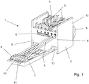
- FIG. 1 shows a perspective view of a Abgriffsteckverbinders 1, which has an insulating 2 with recorded in the insulating 2 contact elements 3.
- the insulating material has 2 web-like projections 4, which are adapted for immersion in grooves of a current-carrying profile (not shown) to contact with the protruding from the webs 4 contact elements 3 arranged in the grooves of the current-carrying profile electrical conductor, if the tapping connector 1 is plugged onto a current-carrying profile.
- connection lines 5 are each connected to the contact elements 3. These connection lines 5 are inserted into conductor insertion openings 6 of the insulating housing 2, at least lead to a contact element 3.
- the contact elements 3 can in this case have a plug contact connection, such as a spring clamp connection, in order to clamp the stripped end of a connecting line 5 to the contact element 3.
- a carrier 7 which is for example plate-shaped and forms a support platform.
- This carrier 7 may be formed integrally with the insulating 2, as shown in the FIG. 1 outlined.
- the carrier 7 is located in the region remote from the contact elements 3, ie at the end of the insulating housing 2, which lies opposite the tapping region with the webs 4 and the contact elements 3.
- the carrier 7 protrudes from a front end 8 of the insulating housing 2 from. It carries at its free end region a conductor holder 9.
- This conductor holder 9 has a number of juxtaposed in a row receiving openings 10, which are adapted to receive the Isolierstoffmantels each a connecting line 5.
- connection lines 5 From the conductor holder 9 then protrude the connection lines 5 with their stripped terminal ends 11 out. In this way, the stripped terminal ends 11 of the connecting lines 5 can be inserted through the conductor holder 9 in orderly orientation in accordance with aligned plugging direction in the ballast.
- the connecting lines 5 are led out of the insulating material housing 2 and then passed past each other so that they end in the required order in the common conductor holder 9. In this case, connecting lines 5 are guided both from the front end face 8, and from the rear end face 12 of the insulating material 2 to the conductor holder 9.
- the connecting lines 5, which are led out of the Isolierstoffgepuruse 2 at the rear end face 12 are guided in the illustrated embodiment by guide grooves 13 at the bottom of the insulating housing 2 on the Abgriffsteckverbinder 1 over to the conductor holder 9.
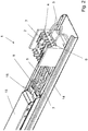
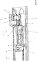
- FIG. 2 shows a perspective view of an arrangement of a Abgriffsteckverbinders 1 in a support section 14 in the connected to a ballast 15 state. It can be seen that the ballast has 15 connector 16 whose Porterein Resultss- or insertion opening are aligned to the Abgriffsteckverbinder 1 indicative.
- connection lines 5 are now electrically conductively connected to the ballast 15 in that the recorded in the conductor holder 9 connecting lines 5 are introduced with the conductor holder 9 in an orderly manner in the connection connector 16 of the ballast 15.
- the carrier 7 is moved together with the Isolierstoffgeophuse 2 of Abgriffsteckverbinders 1 and the conductor holder 9 to the ballast 15 out.
- the tap connector 1 and / or the carrier 7 is connected to the carrier profile 14. This can be done for example by locking. It is also conceivable, however, for the carrier 7 to be screwed or riveted to the carrier profile 14 or to be connected in a form-locking or force-locking manner in some other way.
- the carrier profile 14 has latching elements which are adapted to corresponding latching contours of the insulating housing 2 and / or the carrier 7 in order to lock the tap connector 1 to the carrier profile 14.
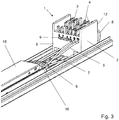
- FIG. 3 shows a perspective view of the arrangement FIG. 2 This is only once again clear that the conductor holder 9 is plugged into the connection connector 16 of the ballast 15 and the insulating 2 of the Abgriffsteckverbinders 1 is at a distance therefrom.
- the carrier 7 By the carrier 7, a predetermined distance between the conductor holder 9 and the insulating 2 of the Abgriffsteckverbinders 1 is specified.
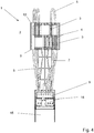
- FIG. 4 shows a plan view of the arrangement Figures 2 and 3 , Here, the plug contours formed by the side by side spaced apart webs 4 of Abgriffsteckverbinders 1 for placement on a power guide profile clearly. It can be seen that in the webs 4, the contact elements 3 are installed, wherein the contact elements 3 protrude with contact tips of the webs 4. It can also be seen that the stripped terminal ends 11 of the connection lines 5 are inserted into the conductor insertion openings provided on the connection plug connectors 16 of the ballast 15 in order to be clamped with spring connection contacts in the interior of the connection plug 16.
- a ballast 15 for example, an electronics for controlling Be light emitting diode as a light source. It is conceivable that the electronics has radio switching elements to turn a light on and off and possibly dimming.
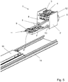
- FIG. 5 shows an exploded view of the Abgriffsteckverbinders 1 in not yet placed on the support section 14 state. It can be seen that the ballast 15 is installed in the carrier profile 14. The insulating housing 2 of the tap connector 1 connected to the carrier 7 is then pushed in one piece into the carrier profile 14 and in the direction of the ballast 15. In this case, the stripped connections are clamped to the connection plug connector 16 of the ballast 15 in the order predetermined by the conductor supports 9 of the connecting leads 5.
- the conductor holder 9 may be formed integrally with the carrier profile 7. It is also conceivable that the conductor holder 9 is a separate part, which is connectable to the carrier profile 7, for example by gluing or latching.
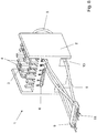
- FIG. 6 shows a perspective top view of the arrangement FIG. 2 and 3 , It is once again more clearly evident here that the flexible lines 5 are guided past one another as required and are rotated in such a way that they are received in the desired sequence at a distance next to each other from the conductor holder 9.
- the carrier 7 may also be formed as a separate part to the insulating housing 2 of the tapping connector 1.
- the insulating housing 2 can then be oriented with a variable distance to the conductor holder 9 and / or with optional alignment with the front end 8 to the conductor holder 9 or rotated by 180 ° with the rear end face 12 to the conductor holder 9 facing.
- the orientation of the contact elements 3 with respect to the conductor holder 9 and the ballast can be adjusted as needed.
- FIG. 7 shows a side view of the arrangement FIGS. 2 to 4 and 6
- the variant is outlined with arrows that the insulating 2 can be moved in the x direction on the support 7 or rotated by 180 ° on the support 7 can be placed.
- the plug positions can be predetermined step by step. It is also conceivable, however, for the carrier 7 to be adapted to the contour of the insulating housing 2 such that the relative position of the insulating housing 2 on the carrier 7 can be optionally fixed, for example by frictional engagement.
- FIG. 8 shows another embodiment of a Abgriffsteckverbinders 1 with flying conductor holder 9.
- the distance and the orientation of the conductor holder to Isolierstoffgeophuse 2 of Abgriffsteckverbinders 1 can be set even more flexible.
- the structure is much simpler than in the previously described embodiment, although a guide element for mounting in the form of the carrier 7 is missing.
Landscapes
- Connector Housings Or Holding Contact Members (AREA)
- Details Of Connecting Devices For Male And Female Coupling (AREA)
Abstract
Description
- Die Erfindung betrifft einen Abgriffsteckverbinder mit einem Isolierstoffgehäuse und mit Kontaktelementen zur elektrisch leitenden Kontaktierung von elektrischen Leitern eines Stromführungsprofils, wenn der Abgriffsteckverbinder auf das Stromführungsprofil aufgesteckt ist.
- Zur Verteilung von elektrischer Energie in Gebäuden und zum Anschließen von Leuchten an wahlweise ausgewählten Positionen sind Stromschienenanordnungen mit Stromführungsprofilen bekannt. Die Stromführungsprofile haben beispielsweise einen kammartigen Querschnitt mit Stegen und hierdurch gebildeten Nuten sowie in den Nuten aufgenommene elektrische Leiter. Bei solchen Stromführungsprofilen sind die elektrischen Leiter in die Nuten eingebaut und können von einem Abgriffsteckverbinder mit in die Nuten hineinragenden Kontaktelementen elektrisch leitend kontaktiert werden. Mit diesen Kontaktelementen sind dann Anschlussleitungen elektrisch leitend verbunden, die entweder als Zuleitung elektrischer Energie oder als Ableitungen zur Verdrahtung mit einer Leuchte genutzt werden. Solche Leuchten haben oftmals Vorschaltgeräte, die zwischen dem Leuchtmittel und dem Abgriffstecker geschaltet werden. Solche Vorschaltgeräte können beispielsweise eine geeignete Elektronik zum Ansteuern von Leuchtdioden als Leuchtmittel, von Gasentladungsröhren oder Ähnliches sein. Vorschaltgeräte können auch eine Elektronik zum funkgesteuerten Ein-/Ausschalten sowie Dimmen der Leuchte haben.
- Zur Steckkontaktierung von Anschlussleitungen sind Steckverbinder bekannt.
-
US 5,149,280 A offenbart einen Steckverbinder, der aus einem Leiterhalteelement aus Kunststoffmaterial gebildet ist, in den die elektrischen Leiter nebeneinander eingelegt und durch umbiegen verstemmt werden. Die abisolierten Enden der elektrischen Leiter sind dann so ausgerichtet, dass sie in einen korrespondierenden Steckverbinder eingesteckt werden können. -
DE 10 2015 111 675 A1 zeigt einen Steckverbinder mit einem Isolierstoffgehäuse, das Leitereinführungsöffnungen zum Einführen elektrischer Leiter hat. Quer zur Leitereinführungsöffnung ist eine Werkzeugaufnahmeöffnung angeordnet, um mit einem in die Werkzeugaufnahmeöffnung eingeführten Werkzeug einen Abschnitt eines abisolierten Endes des in die Leitereinführungsöffnung eingeführten elektrischen Leiters zu verformen. - Ausgehend hiervon ist es Aufgabe der vorliegenden Erfindung, einen verbesserten Abgriffsteckverbinder zu schaffen, der bei möglichst einfachem Aufbau einen möglichst flexiblen aber definierten Anschluss der Anschlussleitungen an ein Vorschaltgerät ermöglicht und dabei hinsichtlich seiner Lage zum Vorschaltgerät und dem Stromführungsprofil wahlweise ausgerichtet werden kann.
- Die Aufgabe wird mit dem Abgriffsteckverbinder mit den Merkmalen des Anspruchs 1 gelöst. Vorteilhafte Ausführungsformen sind den Unteransprüchen beschrieben.
- Der Abgriffsteckverbinder hat eine Leiterhalterung, die mehrere Anschlussleitungen in einer zum Anschluss der Anschlussleitungen an ein Vorschaltgerät angepassten Lage trägt. Die Anschlussleitungen erstrecken sich fliegend zwischen jeweils einem Kontaktelement und einem Steckplatz der Leiterhalterung. Es wird somit vorgeschlagen, dass an die Kontaktelemente des Abgriffsteckverbinders flexible Anschlussleitungen angeschlossen werden, die in der gewünschten Ausrichtung wahlweise zu einer gemeinsamen Leiterhalterung geführt werden. Unter "flexiblen Anschlussleitungen" werden verformbare Leitungen mit ein- oder mehrdrähtigem Leiter verstanden. Die Anschlussleitungen sind dann in der zum Anschluss an das Vorschaltgerät benötigen Reihenfolge und Ausrichtung mit der Leiterhalterung verbunden. Die Ausrichtung des Abgriffsteckverbinders zur Leiterhalterung ist mit Hilfe der flexiblen Anschlussleitungen wahlweise anpassbar.
- Die Leiterhalterung kann mehrere nebeneinander angeordnete Aufnahmeöffnungen zur Aufnahme einer Anschlussleitung haben. Die Anschlussleitungen sind dann jeweils in eine Aufnahmeöffnung hineingesteckt und stehen mit einem abisolierten Anschlussende aus der Aufnahmeöffnung heraus. Damit kann die Leiterhalterung mit den abragenden abisolierten Anschlussenden in einen Anschlusssteckverbinder eines Vorschaltgerätes eingesteckt werden.
- Die Anschlussleitungen können in einer Reihe beabstandet nebeneinander durch eine Leiterhalterung getragen sein. Insofern hat die Leiterhalterung dann mehrere nebeneinander im Abstand angeordnete Aufnahmeöffnungen für jeweils eine Anschlussleitung.
- Es kann nicht nur eine Reihe von solchen jeweils beabstandet nebeneinander an der Leiterhalterung vorgesehenen Aufnahmeöffnungen vorhanden sein. Denkbar ist auch, dass mindestens zwei Reihen von solchen jeweils beabstandet nebeneinander an der Leiterhalterung getragenen Anschlussleitungen vorhanden sind. Damit können mehrere Anschlussleitungen mit verringertem Platzbedarf in Richtung der Breite, d. h. in Richtung der Länge der Leiterhalterung angeschlossen werden. Die Anschlussleitungen werden dann vorzugsweise klemmend in den Aufnahmeöffnungen gehalten und sind mittels Reibschluss gegen Herausziehen zumindest bis zu einem gewissen Grenzmaß gesichert. Ferner können in den Aufnahmeöffnungen auch Rasthaken angeordnet sein, welche sich in die Isolierung der Anschlussleitungen eingraben und als Widerhaken wirken. Alternativ können die Anschlussleitungen in den Aufnahmeöffnungen der Leiterhalterung mittels Kleben oder dergleichen festgelegt werden. Weiterhin können die Anschlussleitungen auch entsprechend der Offenbarung der eingangs genannten
DE 10 2015 111 675 A1 in der Leiterhalterung festgelegt werden. - Von dem Isolierstoffgehäuse kann ein Träger abragen, der zum Tragen der Leiterhalterung ausgebildet ist. Der Träger kann beispielsweise plattenförmig sein und damit eine Trägerplattform bereitstellen. Der Träger kann einstückig mit dem Isolierstoffgehäuse des Abgriffsteckverbinders ausgebildet sein. Denkbar ist aber auch, dass der Träger ein separates Element zu dem Isolierstoffgehäuse ist. Dies hat den Vorteil, dass das Isolierstoffgehäuse dann wahlweise in unterschiedlichen Relativpositionen und/oder Ausrichtungen mit dem Träger verbindbar ist. So kann das Isolierstoffgehäuse und damit die Ausrichtung des Abgriffsteckverbinders auf diese Weise in Bezug auf ein Vorschaltgerät in jeweils um 180° gedrehten Positionen angeordnet werden. Bei geeigneter Ausbildung der Befestigungselemente für das Isolierstoffgehäuse an dem Träger kann ggf. auch der Abstand des Isolierstoffgehäuses zu der Leiterhaltung variiert werden. Die Leiterhaltung kann an dem Träger fest angeordnet oder daran befestigt sein.
- Die Leiterhalterung kann somit nicht nur beispielsweise einstückig mit dem Träger verbunden sein. Denkbar ist, dass die Leiterhalterung auf den von dem Isolierstoffgehäuse entfernten Endbereich des Trägers lösbar bspw. durch Aufrasten befestigbar ist. Hierzu haben der Träger und die Leiterhalterung aneinander angepasste Befestigungskonturen.
- Der Abgriffsteckverbinder kann Rastelemente zum Aufrasten auf das Trägerprofil haben, das auch das Vorschaltgerät trägt. Das von dem Trägerprofil getragene Vorschaltgerät wird dann mit Hilfe der Anschlussleitungen elektrisch leitend mit dem Abgriffsteckverbinder verbunden, indem die Abgriffleitungen geordnet mit Hilfe der Leiterhalterungen in einen Anschlusssteckverbinder des Vorschaltgerätes gesteckt werden. Hierbei wird der Abgriffsteckverbinder ebenso wie das Vorschaltgerät an dem Trägerprofil in der für den Anschluss an das Stromschienenprofil benötigten Position und Lage befestigt, beispielsweise aufgerastet.
- Die Anschlussleitungen können von einer der Leiterhalterung zugewandten vorderen Stirnseite des Isolierstoffgehäuses und von einer der Leiterhalterung abgewandten hinteren Stirnseite des Isolierstoffgehäuses zu der Leiterhalterung geführt sein. Durch die Nutzung der flexiblen, d. h. verformbaren, starren oder mehrdrähtigen Leiter, Anschlussleitungen können somit die Kontaktelemente des Abgriffsteckverbinders beidseits von der vorderen Stirnseite und der hinteren Stirnseite mit den Anschlussleitungen kontaktiert werden. Diese werden dann an dem Isolierstoffgehäuse seitlich oder unterhalb des Isolierstoffgehäuses durch Führungsnuten zur Leiterhalterung geführt.
- Die Leiterhalterung kann Steckkontakte haben, die jeweils zur elektrisch leitenden Kontaktierung eines Anschlusssteckers eines Vorschaltgerätes und zum Anklemmen einer Anschlussleitung ausgebildet sind. Bei dieser Ausführungsform werden dann nicht die abisolierten Anschlussleitungen direkt zur Steckkontaktierung des Vorschaltgerätes genutzt. Vielmehr hat die Leiterhalterung Steckkontakte in Form eines Zwischensteckverbinders, der auf einer Seite Leiteranschlusskontakte beispielsweise in Form eines Federklemmkontakts zum Anklemmen des abisolierten Endes einer Anschlussleitung und an den diametral einander gegenüberliegenden Enden einen Steckkontaktbereich beispielsweise in Form eines Stiftkontaktes für die Stiftkontakte des Vorschaltgerätes aufweist.
- Die Erfindung wird nachfolgend anhand eines Ausführungsbeispiels mit den beigefügten Zeichnungen näher erläutert. Es zeigen:
- Figur 1 -
- Perspektivische Ansicht einer ersten Ausführungsform eines Abgriffsteckverbinders mit an einem Träger angeordneten Leiterhalterung;
- Figur 2 -
- Perspektivische Ansicht eines Trägerprofils mit Abgriffsteckverbinder und Vorschaltgerät;
- Figur 3 -
- Perspektivische Ansicht der Anordnung aus
Figur 2 mit Blick auf den Abgriffsteckverbinder; - Figur 4 -
- Draufsicht auf den an ein Vorschaltgerät angeschlossenen Abgriffsteckverbinder;
- Figur 5 -
- Perspektivische Explosionsansicht des Trägerprofils mit daran angeordnetem Vorschaltgerät und davon separatem Abgriffsteckverbinder;
- Figur 6 -
- Perspektivische Draufsicht auf die Anordnung aus
Figur 2 und3 ; - Figur 7 -
- eine Seitenansicht der Anordnung aus
Figuren 2 bis 4 und6 - Figur 8 -
- Perspektivische Ansicht eines Abgriffsteckverbinders mit fliegender Leiterhalterung.
-
Figur 1 zeigt eine perspektivische Ansicht eines Abgriffsteckverbinders 1, der ein Isolierstoffgehäuse 2 mit in dem Isolierstoffgehäuse 2 aufgenommenen Kontaktelementen 3 hat. An der Steckseite des Abgriffsteckverbinders 1 hat das Isolierstoffgehäuse 2 stegartige Vorsprünge 4, die zum Eintauchen in Nuten eines Stromführungsprofils (nicht dargestellt) angepasst sind, um mit den aus den Stegen 4 herausragenden Kontaktelementen 3 in den Nuten des Stromführungsprofils angeordnete elektrische Leiter zu kontaktieren, wenn der Abgriffsteckverbinder 1 auf ein Stromführungsprofil aufgesteckt ist. - Um nun eine elektrisch leitende Verbindung des Abgriffsteckverbinders 1 mit einem Vorschaltgerät (nicht dargestellt) herzustellen, sind flexible Anschlussleitungen 5 jeweils mit den Kontaktelementen 3 verbunden. Diese Anschlussleitungen 5 sind in Leitereinführungsöffnungen 6 des Isolierstoffgehäuses 2 eingesteckt, die zumindest an ein Kontaktelement 3 führen. Die Kontaktelemente 3 können hierbei einen Steckkontaktanschluss, wie beispielsweise einen Federklemmanschluss haben, um das abisolierte Ende einer Anschlussleitung 5 an das Kontaktelement 3 anzuklemmen.
- Von dem Isolierstoffgehäuse 2 ragt ein Träger 7 ab, der beispielsweise plattenförmig ist und eine Trägerplattform bildet. Dieser Träger 7 kann einstückig mit dem Isolierstoffgehäuse 2 ausgeformt sein, wie dies in der
Figur 1 skizziert ist. Der Träger 7 befindet sich dabei in dem von den Kontaktelementen 3 entfernten Bereich, d. h. an dem Ende des Isolierstoffgehäuses 2, welches dem Abgriffbereich mit den Stegen 4 und den Kontaktelementen 3 gegenüberliegt. Der Träger 7 ragt dabei von einer vorderen Stirnseite 8 des Isolierstoffgehäuses 2 ab. Er trägt an seinem freien Endbereich eine Leiterhalterung 9. Diese Leiterhalterung 9 hat eine Anzahl von nebeneinander in einer Reihe angeordnete Aufnahmeöffnungen 10, die zur Aufnahme des Isolierstoffmantels jeweils einer Anschlussleitung 5 angepasst sind. Aus der Leiterhalterung 9 ragen dann die Anschlussleitungen 5 mit ihren abisolierten Anschlussenden 11 heraus. Auf diese Weise können die abisolierten Anschlussenden 11 der Anschlussleitungen 5 durch die Leiterhalterung 9 in geordneter Ausrichtung in entsprechend ausgerichteter Steckrichtung in das Vorschaltgerät eingesteckt werden. Deutlich wird, dass die Anschlussleitungen 5 aus dem Isolierstoffgehäuse 2 herausgeführt und dann so aneinander vorbeigeführt sind, dass sie in der benötigten Reihenfolge in der gemeinsamen Leiterhalterung 9 enden. Dabei sind Anschlussleitungen 5 sowohl von der vorderen Stirnseite 8, als auch von der hinteren Stirnseite 12 des Isolierstoffgehäuses 2 zu der Leiterhalterung 9 geführt. Die Anschlussleitungen 5, die an der hinteren Stirnseite 12 aus dem Isolierstoffgehäuse 2 herausgeführt sind, werden im dargestellten Ausführungsbeispiel durch Führungsnuten 13 am Boden des Isolierstoffgehäuses 2 an dem Abgriffsteckverbinder 1 vorbei zu der Leiterhalterung 9 geführt. -
Figur 2 zeigt eine perspektivische Ansicht einer Anordnung eines Abgriffsteckverbinders 1 in einem Trägerprofil 14 in dem an ein Vorschaltgerät 15 angeschlossenen Zustand. Es ist erkennbar, dass das Vorschaltgerät 15 Anschlusssteckverbinder 16 hat, deren Leitereinführungs- bzw. Stecköffnung zu dem Abgriffsteckverbinder 1 hinweisend ausgerichtet sind. - Die Anschlussleitungen 5 werden nun dadurch mit dem Vorschaltgerät 15 elektrisch leitend verbunden, dass die in der Leiterhalterung 9 aufgenommenen Anschlussleitungen 5 mit der Leiterhalterung 9 in geordneter Weise in die Anschlusssteckverbinder 16 des Vorschaltgerätes 15 eingeführt werden. Dies erfolgt, indem der Träger 7 zusammen mit dem Isolierstoffgehäuse 2 des Abgriffsteckverbinders 1 und der Leiterhalterung 9 zum Vorschaltgerät 15 hin bewegt wird. Anschließend wird der Abgriffsteckverbinder 1 und/oder der Träger 7 mit dem Trägerprofil 14 verbunden. Dies kann beispielsweise durch Verrasten erfolgen. Denkbar ist aber auch, dass der Träger 7 mit dem Trägerprofil 14 verschraubt oder vernietet oder auf sonstige Weise form- oder kraftschlüssig verbunden wird. Bevorzugt hat das Trägerprofil 14 Rastelemente, die an korrespondierende Rastkonturen des Isolierstoffgehäuses 2 und/oder des Trägers 7 angepasst sind, um den Abgriffsteckverbinder 1 mit dem Trägerprofil 14 zu verrasten.
-
Figur 3 zeigt eine perspektivische Ansicht der Anordnung ausFigur 2 mit Blick auf den Abgriffsteckverbinder 1. Hierbei wird nur nochmals deutlich, dass die Leiterhalterung 9 an die Anschlusssteckverbinder 16 des Vorschaltgerätes 15 angesteckt ist und sich das Isolierstoffgehäuse 2 des Abgriffsteckverbinders 1 im Abstand hierzu befindet. Durch den Träger 7 wird ein vorgegebener Abstand zwischen der Leiterhalterung 9 und dem Isolierstoffgehäuse 2 des Abgriffsteckverbinders 1 vorgegeben. -
Figur 4 zeigt eine Draufsicht auf die Anordnung ausFiguren 2 und3 . Hier werden die durch die nebeneinander im Abstand voneinander angeordneten Stege 4 des Abgriffsteckverbinders 1 gebildeten Steckkonturen zum Aufsetzen auf ein Stromführungsprofil deutlich. Erkennbar ist, dass in den Stegen 4 die Kontaktelemente 3 eingebaut sind, wobei die Kontaktelemente 3 mit Kontaktspitzen aus den Stegen 4 herausragen. Erkennbar ist auch, dass die abisolierten Anschlussenden 11 der Anschlussleitungen 5 in die an den Anschlusssteckverbindern 16 des Vorschaltgerätes 15 vorhandenen Leitereinführungsöffnungen eingesteckt sind, um mit Federanschlusskontakten im Innenraum der Anschlusssteckverbinder 16 angeklemmt zu werden. Ein solches Vorschaltgerät 15 kann beispielsweise eine Elektronik zur Ansteuerung von Leuchtdioden als Leuchtmittel sein. Denkbar ist, dass die Elektronik Funkschaltelemente hat, um eine Leuchte ein- und auszuschalten und ggf. zu dimmen. -
Figur 5 zeigt eine Explosionsansicht des Abgriffsteckverbinders 1 im noch nicht auf das Trägerprofil 14 aufgesetzten Zustand. Erkennbar ist, dass das Vorschaltgerät 15 in das Trägerprofil 14 eingebaut ist. Das mit dem Träger 7 verbundene Isolierstoffgehäuse 2 des Abgriffsteckverbinders 1 wird dann in einem Stück in das Trägerprofil 14 hinein und in Richtung des Vorschaltgerätes 15 geschoben. Dabei werden die abisolierten Anschlusseneden 11 der Anschlussleitungen 5 in der durch die Leiterhalterungen 9 vorgegebenen Ordnung an den Anschlusssteckverbinder 16 des Vorschaltgerätes 15 angeklemmt. Die Leiterhalterung 9 kann einstückig mit dem Trägerprofil 7 ausgeformt sein. Denkbar ist aber auch, dass die Leiterhalterung 9 ein separates Teil ist, das mit dem Trägerprofil 7 beispielsweise durch Verkleben oder Verrasten verbindbar ist. -
Figur 6 zeigt eine perspektivische Draufsicht auf die Anordnung ausFigur 2 und3 . Hierbei ist nochmals deutlicher erkennbar, dass die flexiblen Leitungen 5 bedarfsweise aneinander vorbeigeführt und so verdreht sind, dass sie in der gewünschten Reihenfolge im Abstand nebeneinander von der Leiterhalterung 9 aufgenommen werden. - Der Träger 7 kann aber auch als separates Teil zum Isolierstoffgehäuse 2 des Abgriffsteckverbinders 1 ausgebildet sein. Das Isolierstoffgehäuse 2 kann dann mit einem variierbaren Abstand zur Leiterhalterung 9 und/oder mit wahlweiser Ausrichtung mit der vorderen Stirnseite 8 zur Leiterhalterung 9 hinweisen oder um 180° gedreht mit der hinteren Stirnseite 12 zur Leiterhalterung 9 weisend angeordnet sein. Damit kann die Ausrichtung der Kontaktelemente 3 in Bezug auf die Leiterhalterung 9 und das Vorschaltgerät nach Bedarf angepasst werden.
-
Figur 7 zeigt eine Seitenansicht der Anordnung ausFiguren 2 bis 4 und6 , allerdings ohne das Trägerprofil 14. Hier ist die Variante mit Pfeilen skizziert, dass das Isolierstoffgehäuse 2 in x-Richtung auf dem Träger 7 verschoben werden kann oder um 180° verdreht auf den Träger 7 aufsetzbar ist. Dabei können die Steckpositionen schrittweise vorgegeben sein. Denkbar ist aber auch, dass der Träger 7 an die Kontur des Isolierstoffgehäuses 2 so angepasst ist, dass die Relativposition des Isolierstoffgehäuses 2 an den Träger 7 beispielsweise durch Reibschluss wahlweise festlegbar ist. -
Figur 8 zeigt eine andere Ausführungsform eines Abgriffsteckverbinders 1 mit fliegender Leiterhalterung 9. Hier kann der Abstand und die Ausrichtung der Leiterhalterung zum Isolierstoffgehäuse 2 des Abgriffsteckverbinders 1 noch flexibler festgelegt werden. Durch den Verzicht auf einen Träger 7 ist der Aufbau wesentlich einfacher, als bei der vorher beschriebenen Ausführungsform, wenngleich ein Führungselement für die Montage in Form des Trägers 7 fehlt.
Claims (10)
- Abgriffsteckverbinder (1) mit einem Isolierstoffgehäuse (2) und mit Kontaktelementen (3) zur elektrisch leitenden Kontaktierung von elektrischen Leitern eines Stromführungsprofils, wenn der Abgriffsteckverbinder (1) auf das Stromführungsprofil aufgesteckt ist, dadurch gekennzeichnet, dass der Abgriffsteckverbinder (1) eine Leiterhalterung (9) hat, die mehrere Anschlussleitungen (5) zum Anschluss der Anschlussleitungen (5) an ein Vorschaltgerät (15) trägt, und dass sich die Anschlussleitungen (5) fliegend zwischen jeweils einem Kontaktelement (3) und einem Steckplatz der Leiterhalterung (5) erstrecken.
- Abgriffsteckverbinder (1) nach Anspruch 1, dadurch gekennzeichnet, dass die Leiterhalterung (9) mehrere nebeneinander angeordnete Aufnahmeöffnungen (10) zur Aufnahme einer Anschlussleitung (5) hat, wobei die Anschlussleitungen (5) jeweils in eine Aufnahmeöffnungen (10) hineingesteckt sind und mit einem abisolierten Anschlussende aus der Aufnahmeöffnung (10) herausstehen.
- Abgriffsteckverbinder (1) nach Anspruch 1 oder 2, dadurch gekennzeichnet, dass die Anschlussleitungen (5) in einer Reihe beabstandet nebeneinander an der Leiterhalterung (9) getragen sind.
- Abgriffsteckverbinder (1) nach Anspruch 3, dadurch gekennzeichnet, dass mindestens zwei Reihen von jeweils beabstandet nebeneinander an der Leiterhaltungen (9) getragenen Anschlussleitungen (5) vorhanden sind.
- Abgriffsteckverbinder (1) nach einem der vorhergehenden Ansprüche, dadurch gekennzeichnet, dass ein insbesondere plattenförmiger Träger (7) von dem Isolierstoffgehäuse (2) abragt und zum Tragen der Leiterhalterung (9) ausgebildet ist.
- Abgriffsteckverbinder (1) nach Anspruch 5, dadurch gekennzeichnet, dass die Leiterhalterung (9) an dem von dem Isolierstoffgehäuse (2) entfernten Endbereich des Träger (7) lösbar, insbesondere aufrastbar, befestigt ist.
- Abgriffsteckverbinder (1) nach Anspruch 5 oder 6, dadurch gekennzeichnet, dass das Isolierstoffgehäuse (2) wahlweise in unterschiedlichen Relativpositionen und/oder Ausrichtungen mit dem Träger (7) verbindbar ist.
- Abgriffsteckverbinder (1) nach einem der vorhergehenden Ansprüche, dadurch gekennzeichnet, dass der Abgriffsteckverbinder (1) Rastelemente zum Aufrasten auf ein Trägerprofil (14) hat, dass das Vorschaltgerät (15) trägt.
- Abgriffsteckverbinder (1) nach einem der vorhergehenden Ansprüche, dadurch gekennzeichnet, dass die Anschlussleitungen (5) von einer der Leiterhalterungen (9) zugewandten vorderen Stirnseite (8) des Isolierstoffgehäuses (2) und von einer der Leiterhalterung (9) abgewandeten hinteren Stirnseite (12) des Isolierstoffgehäuses (2) zu der Leiterhalterungen (9) geführt sind.
- Abgriffsteckverbinder (1) nach einem der vorhergehenden Ansprüche, dadurch gekennzeichnet, dass die Leiterhalterung (9) Steckkontakte hat, die jeweils einerseits zur elektrisch leitenden Kontaktierung eines Anschlusssteckverbinders eines Vorschaltgerätes (15) und andererseits zum Anklemmen einer Anschlussleitung (5) ausgebildet sind.
Applications Claiming Priority (1)
| Application Number | Priority Date | Filing Date | Title |
|---|---|---|---|
| DE102017125279.7A DE102017125279A1 (de) | 2017-10-27 | 2017-10-27 | Abgriffsteckverbinder |
Publications (2)
| Publication Number | Publication Date |
|---|---|
| EP3477791A1 true EP3477791A1 (de) | 2019-05-01 |
| EP3477791B1 EP3477791B1 (de) | 2022-12-14 |
Family
ID=63833920
Family Applications (1)
| Application Number | Title | Priority Date | Filing Date |
|---|---|---|---|
| EP18199881.6A Active EP3477791B1 (de) | 2017-10-27 | 2018-10-11 | Abgriffsteckverbinder |
Country Status (3)
| Country | Link |
|---|---|
| EP (1) | EP3477791B1 (de) |
| CN (1) | CN109728470B (de) |
| DE (1) | DE102017125279A1 (de) |
Cited By (2)
| Publication number | Priority date | Publication date | Assignee | Title |
|---|---|---|---|---|
| EP3772611A1 (de) * | 2019-08-06 | 2021-02-10 | Trilux GmbH & Co. KG | System zur realisierung einer leuchte mit elektrischem abgriff mit leiterhalter |
| WO2024056553A1 (de) * | 2022-09-13 | 2024-03-21 | Zumtobel Lighting Gmbh | Anschlussstecker für leuchtentragschienensystem |
Citations (3)
| Publication number | Priority date | Publication date | Assignee | Title |
|---|---|---|---|---|
| US6093037A (en) * | 1999-01-28 | 2000-07-25 | Lin; Shan Chaing | Track and connector arrangement |
| DE102005048490A1 (de) * | 2005-05-07 | 2006-11-09 | Pepperl + Fuchs Gmbh | Kabelverteiler zum elektrischen Anschließen einer Zweigleitung an ein Stammkabel |
| DE102010032383A1 (de) * | 2010-07-27 | 2012-02-02 | Wago Verwaltungsgesellschaft Mbh | Stromschienenverbinder und Stromschienensystem mit mindestens zwei benachbarten Stromschienen und einem Stromschienenverbinder |
Family Cites Families (15)
| Publication number | Priority date | Publication date | Assignee | Title |
|---|---|---|---|---|
| CN87104859A (zh) * | 1986-06-19 | 1988-04-27 | Mba服务有限公司 | 带状电缆传输系统 |
| FR2607976A1 (fr) * | 1986-12-04 | 1988-06-10 | Renault | Dispositif de liaison electrique en multiplexage pour vehicule automobile |
| US5032086A (en) * | 1990-03-19 | 1991-07-16 | Molex Incorporated | Wiring harness for wall structures |
| DE4110740C1 (en) * | 1991-04-03 | 1992-11-26 | Hoffmeister-Leuchten Gmbh & Co Kg, 5880 Luedenscheid, De | Component fixing appts. for triangular-section rail holding bus=bar - has protruding ribs or strips on inner edge of rail, and removable cover forming base of right-angled isosceles triangle |
| US5149280A (en) | 1991-10-09 | 1992-09-22 | Molex Incorporated | Wire holding device for discrete electrical wires |
| US5679023A (en) * | 1995-08-23 | 1997-10-21 | Nsi Enterprises, Inc. | Female cable connector head for relocatable wiring systems and methods for manufacture thereof |
| US6113435A (en) * | 1997-11-18 | 2000-09-05 | Nsi Enterprises, Inc. | Relocatable wiring connection devices |
| US6575777B2 (en) * | 2000-10-30 | 2003-06-10 | Kimball International, Inc. | Partition wiring system |
| US20030021111A1 (en) * | 2001-07-30 | 2003-01-30 | Miller Jack V. | Multi-circuit tracklight system |
| MXPA05007737A (es) * | 2003-01-20 | 2005-11-04 | Automated Media Services Inc | Canal de alimentacion de energia para energizar a dispositivos electronicos que operan ambientes comerciales. |
| DE202007008700U1 (de) * | 2007-06-19 | 2007-08-23 | Wago Verwaltungsgesellschaft Mbh | Leiterplattenklemme |
| DE202008001964U1 (de) * | 2008-02-13 | 2008-04-24 | Ridi Leuchten Gmbh | Verbindungssystem für Lichtbänder oder Leuchten |
| DE102013216275B4 (de) * | 2013-07-15 | 2015-07-02 | Ridi Leuchten Gmbh | Leuchte |
| DE102015111675A1 (de) | 2015-07-17 | 2017-01-19 | Wago Verwaltungsgesellschaft Mbh | Steckverbinder und Verformungswerkzeug hierzu |
| DE102016012370B4 (de) * | 2016-10-15 | 2020-03-26 | Diehl Metering Gmbh | Gehäuse zum Anschließen wenigstens einer Kabellitze eines Kabels |
-
2017
- 2017-10-27 DE DE102017125279.7A patent/DE102017125279A1/de active Pending
-
2018
- 2018-10-11 EP EP18199881.6A patent/EP3477791B1/de active Active
- 2018-10-25 CN CN201811248256.9A patent/CN109728470B/zh active Active
Patent Citations (3)
| Publication number | Priority date | Publication date | Assignee | Title |
|---|---|---|---|---|
| US6093037A (en) * | 1999-01-28 | 2000-07-25 | Lin; Shan Chaing | Track and connector arrangement |
| DE102005048490A1 (de) * | 2005-05-07 | 2006-11-09 | Pepperl + Fuchs Gmbh | Kabelverteiler zum elektrischen Anschließen einer Zweigleitung an ein Stammkabel |
| DE102010032383A1 (de) * | 2010-07-27 | 2012-02-02 | Wago Verwaltungsgesellschaft Mbh | Stromschienenverbinder und Stromschienensystem mit mindestens zwei benachbarten Stromschienen und einem Stromschienenverbinder |
Cited By (2)
| Publication number | Priority date | Publication date | Assignee | Title |
|---|---|---|---|---|
| EP3772611A1 (de) * | 2019-08-06 | 2021-02-10 | Trilux GmbH & Co. KG | System zur realisierung einer leuchte mit elektrischem abgriff mit leiterhalter |
| WO2024056553A1 (de) * | 2022-09-13 | 2024-03-21 | Zumtobel Lighting Gmbh | Anschlussstecker für leuchtentragschienensystem |
Also Published As
| Publication number | Publication date |
|---|---|
| EP3477791B1 (de) | 2022-12-14 |
| CN109728470A (zh) | 2019-05-07 |
| CN109728470B (zh) | 2023-02-10 |
| DE102017125279A1 (de) | 2019-05-02 |
Similar Documents
| Publication | Publication Date | Title |
|---|---|---|
| EP1950836B1 (de) | Elektrische Anschlussklemme | |
| EP3375048B1 (de) | Steckkontakt | |
| DE69013582T2 (de) | Keilförmiger Sockel, befestigt an SPG-Substrat. | |
| EP1887657B1 (de) | Anschlusskontakt für elektrische Leiter | |
| DE102017114730B4 (de) | Leuchtmittel und Federkontakt zur elektrischen Verbindung zweier Platinen | |
| DE202007000185U1 (de) | Eletrischer Verbinder | |
| EP2509171A1 (de) | Leiteranschlussstecker, Steckverbinder und Set aus Leiteranschlussstecker und Steckverbinder | |
| EP3477791B1 (de) | Abgriffsteckverbinder | |
| EP2573883A2 (de) | Abschlusskappe für Stromführungsprofile eines Stromverteileranordnung | |
| EP2856558A1 (de) | Rj45-stecker mit führungseinrichtung für litzen | |
| EP0911914B1 (de) | Elektrisches Kupplungssystem | |
| EP3698438B1 (de) | Vorrichtung zur elektrischen kontaktierung | |
| DE2013542A1 (de) | ||
| AT516443B1 (de) | Leuchte mit Kontaktierungsmodul | |
| DE2641258A1 (de) | Anschlussvorrichtung mit stecksockel fuer elektrische bauteile | |
| EP3772611B1 (de) | System zur realisierung einer leuchte mit elektrischem abgriff mit leiterhalter | |
| EP0894345A1 (de) | Elektrische anschlussvorrichtung und elektrisches verbindungselement zur verwendung in einer elektrischen anschlussvorrichtung | |
| DE102015120980B4 (de) | Leiterplattenanordnung und Leuchtenanordnung | |
| EP0201035B1 (de) | Koaxialkabelanschluss an einer Federleiste | |
| EP0871266A2 (de) | Lampenfassung | |
| DE102012011047B4 (de) | Verbindungsbauteil und Schaltungsanordnung mit dem Verbindungsbauteil | |
| EP2133956A2 (de) | Elektrisches Anschlusselement | |
| EP3435488B1 (de) | Geräteanordnung | |
| DE68909679T2 (de) | Träger für elektrische Verbinder. | |
| DE2015338C3 (de) | Parallelverteiler |
Legal Events
| Date | Code | Title | Description |
|---|---|---|---|
| PUAI | Public reference made under article 153(3) epc to a published international application that has entered the european phase |
Free format text: ORIGINAL CODE: 0009012 |
|
| STAA | Information on the status of an ep patent application or granted ep patent |
Free format text: STATUS: THE APPLICATION HAS BEEN PUBLISHED |
|
| AK | Designated contracting states |
Kind code of ref document: A1 Designated state(s): AL AT BE BG CH CY CZ DE DK EE ES FI FR GB GR HR HU IE IS IT LI LT LU LV MC MK MT NL NO PL PT RO RS SE SI SK SM TR |
|
| AX | Request for extension of the european patent |
Extension state: BA ME |
|
| STAA | Information on the status of an ep patent application or granted ep patent |
Free format text: STATUS: REQUEST FOR EXAMINATION WAS MADE |
|
| 17P | Request for examination filed |
Effective date: 20190927 |
|
| RBV | Designated contracting states (corrected) |
Designated state(s): AL AT BE BG CH CY CZ DE DK EE ES FI FR GB GR HR HU IE IS IT LI LT LU LV MC MK MT NL NO PL PT RO RS SE SI SK SM TR |
|
| STAA | Information on the status of an ep patent application or granted ep patent |
Free format text: STATUS: EXAMINATION IS IN PROGRESS |
|
| STAA | Information on the status of an ep patent application or granted ep patent |
Free format text: STATUS: EXAMINATION IS IN PROGRESS |
|
| 17Q | First examination report despatched |
Effective date: 20201208 |
|
| STAA | Information on the status of an ep patent application or granted ep patent |
Free format text: STATUS: EXAMINATION IS IN PROGRESS |
|
| GRAP | Despatch of communication of intention to grant a patent |
Free format text: ORIGINAL CODE: EPIDOSNIGR1 |
|
| STAA | Information on the status of an ep patent application or granted ep patent |
Free format text: STATUS: GRANT OF PATENT IS INTENDED |
|
| RIC1 | Information provided on ipc code assigned before grant |
Ipc: H01R 9/22 20060101ALN20220503BHEP Ipc: H01R 4/2404 20180101ALN20220503BHEP Ipc: H01R 4/48 20060101ALN20220503BHEP Ipc: H01R 25/14 20060101AFI20220503BHEP |
|
| RIC1 | Information provided on ipc code assigned before grant |
Ipc: H01R 9/22 20060101ALN20220509BHEP Ipc: H01R 4/2404 20180101ALN20220509BHEP Ipc: H01R 4/48 20060101ALN20220509BHEP Ipc: H01R 25/14 20060101AFI20220509BHEP |
|
| INTG | Intention to grant announced |
Effective date: 20220525 |
|
| GRAJ | Information related to disapproval of communication of intention to grant by the applicant or resumption of examination proceedings by the epo deleted |
Free format text: ORIGINAL CODE: EPIDOSDIGR1 |
|
| STAA | Information on the status of an ep patent application or granted ep patent |
Free format text: STATUS: EXAMINATION IS IN PROGRESS |
|
| GRAS | Grant fee paid |
Free format text: ORIGINAL CODE: EPIDOSNIGR3 |
|
| STAA | Information on the status of an ep patent application or granted ep patent |
Free format text: STATUS: GRANT OF PATENT IS INTENDED |
|
| GRAP | Despatch of communication of intention to grant a patent |
Free format text: ORIGINAL CODE: EPIDOSNIGR1 |
|
| INTC | Intention to grant announced (deleted) | ||
| RIC1 | Information provided on ipc code assigned before grant |
Ipc: H01R 9/22 20060101ALN20221003BHEP Ipc: H01R 4/2404 20180101ALN20221003BHEP Ipc: H01R 4/48 20060101ALN20221003BHEP Ipc: H01R 25/14 20060101AFI20221003BHEP |
|
| GRAA | (expected) grant |
Free format text: ORIGINAL CODE: 0009210 |
|
| STAA | Information on the status of an ep patent application or granted ep patent |
Free format text: STATUS: THE PATENT HAS BEEN GRANTED |
|
| INTG | Intention to grant announced |
Effective date: 20221027 |
|
| AK | Designated contracting states |
Kind code of ref document: B1 Designated state(s): AL AT BE BG CH CY CZ DE DK EE ES FI FR GB GR HR HU IE IS IT LI LT LU LV MC MK MT NL NO PL PT RO RS SE SI SK SM TR |
|
| REG | Reference to a national code |
Ref country code: GB Ref legal event code: FG4D Free format text: NOT ENGLISH |
|
| REG | Reference to a national code |
Ref country code: CH Ref legal event code: EP |
|
| REG | Reference to a national code |
Ref country code: DE Ref legal event code: R096 Ref document number: 502018011214 Country of ref document: DE |
|
| REG | Reference to a national code |
Ref country code: IE Ref legal event code: FG4D Free format text: LANGUAGE OF EP DOCUMENT: GERMAN |
|
| REG | Reference to a national code |
Ref country code: AT Ref legal event code: REF Ref document number: 1538236 Country of ref document: AT Kind code of ref document: T Effective date: 20230115 |
|
| REG | Reference to a national code |
Ref country code: LT Ref legal event code: MG9D |
|
| REG | Reference to a national code |
Ref country code: NL Ref legal event code: MP Effective date: 20221214 |
|
| PG25 | Lapsed in a contracting state [announced via postgrant information from national office to epo] |
Ref country code: SE Free format text: LAPSE BECAUSE OF FAILURE TO SUBMIT A TRANSLATION OF THE DESCRIPTION OR TO PAY THE FEE WITHIN THE PRESCRIBED TIME-LIMIT Effective date: 20221214 Ref country code: NO Free format text: LAPSE BECAUSE OF FAILURE TO SUBMIT A TRANSLATION OF THE DESCRIPTION OR TO PAY THE FEE WITHIN THE PRESCRIBED TIME-LIMIT Effective date: 20230314 Ref country code: LT Free format text: LAPSE BECAUSE OF FAILURE TO SUBMIT A TRANSLATION OF THE DESCRIPTION OR TO PAY THE FEE WITHIN THE PRESCRIBED TIME-LIMIT Effective date: 20221214 Ref country code: FI Free format text: LAPSE BECAUSE OF FAILURE TO SUBMIT A TRANSLATION OF THE DESCRIPTION OR TO PAY THE FEE WITHIN THE PRESCRIBED TIME-LIMIT Effective date: 20221214 |
|
| PG25 | Lapsed in a contracting state [announced via postgrant information from national office to epo] |
Ref country code: RS Free format text: LAPSE BECAUSE OF FAILURE TO SUBMIT A TRANSLATION OF THE DESCRIPTION OR TO PAY THE FEE WITHIN THE PRESCRIBED TIME-LIMIT Effective date: 20221214 Ref country code: LV Free format text: LAPSE BECAUSE OF FAILURE TO SUBMIT A TRANSLATION OF THE DESCRIPTION OR TO PAY THE FEE WITHIN THE PRESCRIBED TIME-LIMIT Effective date: 20221214 Ref country code: HR Free format text: LAPSE BECAUSE OF FAILURE TO SUBMIT A TRANSLATION OF THE DESCRIPTION OR TO PAY THE FEE WITHIN THE PRESCRIBED TIME-LIMIT Effective date: 20221214 Ref country code: GR Free format text: LAPSE BECAUSE OF FAILURE TO SUBMIT A TRANSLATION OF THE DESCRIPTION OR TO PAY THE FEE WITHIN THE PRESCRIBED TIME-LIMIT Effective date: 20230315 |
|
| P01 | Opt-out of the competence of the unified patent court (upc) registered |
Effective date: 20230516 |
|
| PG25 | Lapsed in a contracting state [announced via postgrant information from national office to epo] |
Ref country code: NL Free format text: LAPSE BECAUSE OF FAILURE TO SUBMIT A TRANSLATION OF THE DESCRIPTION OR TO PAY THE FEE WITHIN THE PRESCRIBED TIME-LIMIT Effective date: 20221214 |
|
| PG25 | Lapsed in a contracting state [announced via postgrant information from national office to epo] |
Ref country code: SM Free format text: LAPSE BECAUSE OF FAILURE TO SUBMIT A TRANSLATION OF THE DESCRIPTION OR TO PAY THE FEE WITHIN THE PRESCRIBED TIME-LIMIT Effective date: 20221214 Ref country code: RO Free format text: LAPSE BECAUSE OF FAILURE TO SUBMIT A TRANSLATION OF THE DESCRIPTION OR TO PAY THE FEE WITHIN THE PRESCRIBED TIME-LIMIT Effective date: 20221214 Ref country code: PT Free format text: LAPSE BECAUSE OF FAILURE TO SUBMIT A TRANSLATION OF THE DESCRIPTION OR TO PAY THE FEE WITHIN THE PRESCRIBED TIME-LIMIT Effective date: 20230414 Ref country code: ES Free format text: LAPSE BECAUSE OF FAILURE TO SUBMIT A TRANSLATION OF THE DESCRIPTION OR TO PAY THE FEE WITHIN THE PRESCRIBED TIME-LIMIT Effective date: 20221214 Ref country code: EE Free format text: LAPSE BECAUSE OF FAILURE TO SUBMIT A TRANSLATION OF THE DESCRIPTION OR TO PAY THE FEE WITHIN THE PRESCRIBED TIME-LIMIT Effective date: 20221214 Ref country code: CZ Free format text: LAPSE BECAUSE OF FAILURE TO SUBMIT A TRANSLATION OF THE DESCRIPTION OR TO PAY THE FEE WITHIN THE PRESCRIBED TIME-LIMIT Effective date: 20221214 |
|
| PG25 | Lapsed in a contracting state [announced via postgrant information from national office to epo] |
Ref country code: SK Free format text: LAPSE BECAUSE OF FAILURE TO SUBMIT A TRANSLATION OF THE DESCRIPTION OR TO PAY THE FEE WITHIN THE PRESCRIBED TIME-LIMIT Effective date: 20221214 Ref country code: PL Free format text: LAPSE BECAUSE OF FAILURE TO SUBMIT A TRANSLATION OF THE DESCRIPTION OR TO PAY THE FEE WITHIN THE PRESCRIBED TIME-LIMIT Effective date: 20221214 Ref country code: IS Free format text: LAPSE BECAUSE OF FAILURE TO SUBMIT A TRANSLATION OF THE DESCRIPTION OR TO PAY THE FEE WITHIN THE PRESCRIBED TIME-LIMIT Effective date: 20230414 Ref country code: AL Free format text: LAPSE BECAUSE OF FAILURE TO SUBMIT A TRANSLATION OF THE DESCRIPTION OR TO PAY THE FEE WITHIN THE PRESCRIBED TIME-LIMIT Effective date: 20221214 |
|
| REG | Reference to a national code |
Ref country code: DE Ref legal event code: R097 Ref document number: 502018011214 Country of ref document: DE |
|
| PLBE | No opposition filed within time limit |
Free format text: ORIGINAL CODE: 0009261 |
|
| STAA | Information on the status of an ep patent application or granted ep patent |
Free format text: STATUS: NO OPPOSITION FILED WITHIN TIME LIMIT |
|
| PG25 | Lapsed in a contracting state [announced via postgrant information from national office to epo] |
Ref country code: DK Free format text: LAPSE BECAUSE OF FAILURE TO SUBMIT A TRANSLATION OF THE DESCRIPTION OR TO PAY THE FEE WITHIN THE PRESCRIBED TIME-LIMIT Effective date: 20221214 |
|
| 26N | No opposition filed |
Effective date: 20230915 |
|
| PG25 | Lapsed in a contracting state [announced via postgrant information from national office to epo] |
Ref country code: SI Free format text: LAPSE BECAUSE OF FAILURE TO SUBMIT A TRANSLATION OF THE DESCRIPTION OR TO PAY THE FEE WITHIN THE PRESCRIBED TIME-LIMIT Effective date: 20221214 |
|
| PGFP | Annual fee paid to national office [announced via postgrant information from national office to epo] |
Ref country code: DE Payment date: 20231027 Year of fee payment: 6 |
|
| PG25 | Lapsed in a contracting state [announced via postgrant information from national office to epo] |
Ref country code: IT Free format text: LAPSE BECAUSE OF FAILURE TO SUBMIT A TRANSLATION OF THE DESCRIPTION OR TO PAY THE FEE WITHIN THE PRESCRIBED TIME-LIMIT Effective date: 20221214 Ref country code: MC Free format text: LAPSE BECAUSE OF FAILURE TO SUBMIT A TRANSLATION OF THE DESCRIPTION OR TO PAY THE FEE WITHIN THE PRESCRIBED TIME-LIMIT Effective date: 20221214 |
|
| REG | Reference to a national code |
Ref country code: CH Ref legal event code: PL |
|
| REG | Reference to a national code |
Ref country code: BE Ref legal event code: MM Effective date: 20231031 |
|
| PG25 | Lapsed in a contracting state [announced via postgrant information from national office to epo] |
Ref country code: LU Free format text: LAPSE BECAUSE OF NON-PAYMENT OF DUE FEES Effective date: 20231011 |
|
| GBPC | Gb: european patent ceased through non-payment of renewal fee |
Effective date: 20231011 |
|
| PG25 | Lapsed in a contracting state [announced via postgrant information from national office to epo] |
Ref country code: LU Free format text: LAPSE BECAUSE OF NON-PAYMENT OF DUE FEES Effective date: 20231011 |
|
| PG25 | Lapsed in a contracting state [announced via postgrant information from national office to epo] |
Ref country code: GB Free format text: LAPSE BECAUSE OF NON-PAYMENT OF DUE FEES Effective date: 20231011 |
|
| PG25 | Lapsed in a contracting state [announced via postgrant information from national office to epo] |
Ref country code: CH Free format text: LAPSE BECAUSE OF NON-PAYMENT OF DUE FEES Effective date: 20231031 |
|
| PG25 | Lapsed in a contracting state [announced via postgrant information from national office to epo] |
Ref country code: GB Free format text: LAPSE BECAUSE OF NON-PAYMENT OF DUE FEES Effective date: 20231011 Ref country code: FR Free format text: LAPSE BECAUSE OF NON-PAYMENT OF DUE FEES Effective date: 20231031 Ref country code: CH Free format text: LAPSE BECAUSE OF NON-PAYMENT OF DUE FEES Effective date: 20231031 |
|
| PG25 | Lapsed in a contracting state [announced via postgrant information from national office to epo] |
Ref country code: BE Free format text: LAPSE BECAUSE OF NON-PAYMENT OF DUE FEES Effective date: 20231031 |
|
| PG25 | Lapsed in a contracting state [announced via postgrant information from national office to epo] |
Ref country code: IE Free format text: LAPSE BECAUSE OF NON-PAYMENT OF DUE FEES Effective date: 20231011 |