EP1233209B1 - Verschiebeeinrichtung mit einem in eine Zahnstange eingreifenden Zahnriemen - Google Patents
Verschiebeeinrichtung mit einem in eine Zahnstange eingreifenden Zahnriemen Download PDFInfo
- Publication number
- EP1233209B1 EP1233209B1 EP01810071A EP01810071A EP1233209B1 EP 1233209 B1 EP1233209 B1 EP 1233209B1 EP 01810071 A EP01810071 A EP 01810071A EP 01810071 A EP01810071 A EP 01810071A EP 1233209 B1 EP1233209 B1 EP 1233209B1
- Authority
- EP
- European Patent Office
- Prior art keywords
- pressure
- gear rack
- toothed belt
- wheel
- sliding device
- Prior art date
- Legal status (The legal status is an assumption and is not a legal conclusion. Google has not performed a legal analysis and makes no representation as to the accuracy of the status listed.)
- Expired - Lifetime
Links
- 238000006073 displacement reaction Methods 0.000 title description 12
- 230000002093 peripheral effect Effects 0.000 description 2
- 229920003023 plastic Polymers 0.000 description 2
- 239000004033 plastic Substances 0.000 description 2
- 239000004698 Polyethylene Substances 0.000 description 1
- 238000005299 abrasion Methods 0.000 description 1
- 230000005540 biological transmission Effects 0.000 description 1
- 230000007423 decrease Effects 0.000 description 1
- 230000000694 effects Effects 0.000 description 1
- 239000013013 elastic material Substances 0.000 description 1
- 230000001771 impaired effect Effects 0.000 description 1
- 239000000463 material Substances 0.000 description 1
- -1 polyethylene Polymers 0.000 description 1
- 229920000573 polyethylene Polymers 0.000 description 1
- 229920002635 polyurethane Polymers 0.000 description 1
- 239000004814 polyurethane Substances 0.000 description 1
- 239000000126 substance Substances 0.000 description 1
Images




Classifications
-
- F—MECHANICAL ENGINEERING; LIGHTING; HEATING; WEAPONS; BLASTING
- F16—ENGINEERING ELEMENTS AND UNITS; GENERAL MEASURES FOR PRODUCING AND MAINTAINING EFFECTIVE FUNCTIONING OF MACHINES OR INSTALLATIONS; THERMAL INSULATION IN GENERAL
- F16H—GEARING
- F16H19/00—Gearings comprising essentially only toothed gears or friction members and not capable of conveying indefinitely-continuing rotary motion
- F16H19/02—Gearings comprising essentially only toothed gears or friction members and not capable of conveying indefinitely-continuing rotary motion for interconverting rotary or oscillating motion and reciprocating motion
- F16H19/06—Gearings comprising essentially only toothed gears or friction members and not capable of conveying indefinitely-continuing rotary motion for interconverting rotary or oscillating motion and reciprocating motion comprising flexible members, e.g. an endless flexible member
-
- B—PERFORMING OPERATIONS; TRANSPORTING
- B23—MACHINE TOOLS; METAL-WORKING NOT OTHERWISE PROVIDED FOR
- B23Q—DETAILS, COMPONENTS, OR ACCESSORIES FOR MACHINE TOOLS, e.g. ARRANGEMENTS FOR COPYING OR CONTROLLING; MACHINE TOOLS IN GENERAL CHARACTERISED BY THE CONSTRUCTION OF PARTICULAR DETAILS OR COMPONENTS; COMBINATIONS OR ASSOCIATIONS OF METAL-WORKING MACHINES, NOT DIRECTED TO A PARTICULAR RESULT
- B23Q5/00—Driving or feeding mechanisms; Control arrangements therefor
- B23Q5/22—Feeding members carrying tools or work
- B23Q5/34—Feeding other members supporting tools or work, e.g. saddles, tool-slides, through mechanical transmission
- B23Q5/38—Feeding other members supporting tools or work, e.g. saddles, tool-slides, through mechanical transmission feeding continuously
- B23Q5/385—Feeding other members supporting tools or work, e.g. saddles, tool-slides, through mechanical transmission feeding continuously using a gear and rack mechanism or a friction wheel co-operating with a rail
-
- F—MECHANICAL ENGINEERING; LIGHTING; HEATING; WEAPONS; BLASTING
- F16—ENGINEERING ELEMENTS AND UNITS; GENERAL MEASURES FOR PRODUCING AND MAINTAINING EFFECTIVE FUNCTIONING OF MACHINES OR INSTALLATIONS; THERMAL INSULATION IN GENERAL
- F16H—GEARING
- F16H19/00—Gearings comprising essentially only toothed gears or friction members and not capable of conveying indefinitely-continuing rotary motion
- F16H19/02—Gearings comprising essentially only toothed gears or friction members and not capable of conveying indefinitely-continuing rotary motion for interconverting rotary or oscillating motion and reciprocating motion
- F16H19/06—Gearings comprising essentially only toothed gears or friction members and not capable of conveying indefinitely-continuing rotary motion for interconverting rotary or oscillating motion and reciprocating motion comprising flexible members, e.g. an endless flexible member
- F16H2019/0613—Gearings comprising essentially only toothed gears or friction members and not capable of conveying indefinitely-continuing rotary motion for interconverting rotary or oscillating motion and reciprocating motion comprising flexible members, e.g. an endless flexible member the flexible member being a toothed belt or chain engaging a rack
-
- Y—GENERAL TAGGING OF NEW TECHNOLOGICAL DEVELOPMENTS; GENERAL TAGGING OF CROSS-SECTIONAL TECHNOLOGIES SPANNING OVER SEVERAL SECTIONS OF THE IPC; TECHNICAL SUBJECTS COVERED BY FORMER USPC CROSS-REFERENCE ART COLLECTIONS [XRACs] AND DIGESTS
- Y10—TECHNICAL SUBJECTS COVERED BY FORMER USPC
- Y10T—TECHNICAL SUBJECTS COVERED BY FORMER US CLASSIFICATION
- Y10T74/00—Machine element or mechanism
- Y10T74/18—Mechanical movements
- Y10T74/18568—Reciprocating or oscillating to or from alternating rotary
- Y10T74/18832—Reciprocating or oscillating to or from alternating rotary including flexible drive connector [e.g., belt, chain, strand, etc.]
-
- Y—GENERAL TAGGING OF NEW TECHNOLOGICAL DEVELOPMENTS; GENERAL TAGGING OF CROSS-SECTIONAL TECHNOLOGIES SPANNING OVER SEVERAL SECTIONS OF THE IPC; TECHNICAL SUBJECTS COVERED BY FORMER USPC CROSS-REFERENCE ART COLLECTIONS [XRACs] AND DIGESTS
- Y10—TECHNICAL SUBJECTS COVERED BY FORMER USPC
- Y10T—TECHNICAL SUBJECTS COVERED BY FORMER US CLASSIFICATION
- Y10T74/00—Machine element or mechanism
- Y10T74/18—Mechanical movements
- Y10T74/18568—Reciprocating or oscillating to or from alternating rotary
- Y10T74/18832—Reciprocating or oscillating to or from alternating rotary including flexible drive connector [e.g., belt, chain, strand, etc.]
- Y10T74/1884—Reciprocating or oscillating to or from alternating rotary including flexible drive connector [e.g., belt, chain, strand, etc.] with sprocket wheel
Definitions
- the invention relates to a displacement device according to the Preamble of claim 1.
- Such displacement devices to be considered generally known can be used in different fields are such as in laboratory equipment, e.g. B. pipetting devices for chemical analysis and etc. ..
- the invention is based on the object generic shifting device to specify which works silently and trouble-free and a jerk-free and precisely controllable movement of the carriage is guaranteed and is simply constructed. This task is accomplished by the Invention as characterized in claim 1 solved.
- the advantages of the displacement device according to the invention are particularly useful in laboratory equipment, where the above properties are particularly desirable. That the power transmission is also maintenance-free, is a more essential, especially in a laboratory device Advantage.
- the displacement unit according to the invention is therefore suitable excellent for moving lifting and lowering Arms carrying pipettes or robotic arms for handling of test tubes, microtiter plates and the like etc. ..
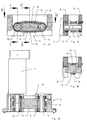
- the displacement device has (FIG. 1) a guide 1 along which several carriages 2 are movable.
- the guide 1 comprises a Guide rod 3 formed round cross-section Guide rail with which each of the carriage 2 by means of a Carriage 4 engages. Parallel to the guide rod 3 runs a rack 5 with upward Toothing.
- Each of the carriages 2 has one on the carriage 4 connecting drive unit 6 and one to this subsequent motor 7 to drive the same.
- the Drive unit 6 is a housing with a base plate 8 and a parallel cover plate 9 spaced from the same and between them a gear wheel to the rack 5 vertical axis formed drive wheel 10 which on the attached to the rack 5 vertical axis of the motor 7 and is driven by the same.
- a deflection wheel 11 is arranged, which is the same as the drive wheel 10, in particular also formed as a gear and whose axis is also perpendicular to the rack 5.
- the Drive wheel 10 and the deflection wheel 11 are both in the housing rotatable, but axially fixed.
- toothed belt 12 made of elastic Material, e.g. B. a plastic such as polyurethane, the one has internal toothing, which with said wheels engages as well as an external toothing, which with the Toothing of the rack 5 (see FIG. 4) engages.
- elastic Material e.g. B. a plastic such as polyurethane
- the pressure block 13 which is made of a material with good Sliding properties, preferably a suitable plastic how ultra high molecular weight low pressure polyethylene is made, has a pressing surface 14, with which he against the the rack 5 opposite lower run of the Timing belt 12 presses.
- the pressing surface 14 has one straight middle section with several, z. B. three or four teeth of the external toothing of the toothed belt 12 overlapped and smooth on both sides convex curved sections.
- One for side guidance of the toothed belt 12 somewhat sunk upper Counter surface 15 is formed exactly the same and stands with the top strand facing away from the rack 5 Timing belt 12 in contact.
- the distance between the pressing surface 14 and the counter surface 15 slightly larger than the inner radius - d. H. the radius apart from the toothing - the Drive wheel 10 and the deflection wheel 11.
- the Center distance of the said wheels so dimensioned that the Timing belt 12 is stretched slightly elastically. So that’s practicing upper strand of the same over the counter surface 15 an elastic Force on the pressure block 13, so that its Press surface 14 in turn against the rack 5 directed elastic force on the middle section of the exerts lower run of the toothed belt 12, which the same the rack 5 presses.
- the drive unit 6, in particular the arrangement consisting of the drive wheel 10, the deflection wheel 11, the toothed belt 12 and the pressure block 13 is with respect to one in the middle between the axes of the said wheels lying vertical plane essentially symmetrical.
- the carriages 2 are replaced by appropriate ones Control of the motors 7 driven independently and the carriage 2 moved along the guide 1.
- the lower Run of the toothed belt 12 is in each case from the Direction of movement independently if it is with the convex section of the pressing surface in front of each 14 comes into contact and continues to slide over it, so on the rack 5 pressed that the engagement of his external gearing with the same against the middle of the Drive unit 6 steadily reinforced over a short distance remains the same and then steadily decreases again. friction between the teeth and corresponding sounds and Irregularities in the movement become extensive as a result avoided.
- the Drive unit (Fig. 5a-c) is the pressing part as Pressure wheel 13 'formed a pinion that between the upper and lower run of the toothed belt 12 rotatable is arranged and its interlocking with its inner Interlocking meshes above and below.
- Diameter is slightly larger than that of the drive wheel 10 and the deflection wheel 11 and the toothed belt 12 in turn is slightly elastically stretched, it transmits (see a. Fig.
Landscapes
- Engineering & Computer Science (AREA)
- Mechanical Engineering (AREA)
- General Engineering & Computer Science (AREA)
- Transmission Devices (AREA)
Description
Es zeigen
- Fig. 1
- perspektivisch eine erfindungsgemässe Verschiebeeinrichtung mit mehreren Wagen,
- Fig. 2
- perspektivisch einen Motor und einen Teil einer Antriebseinheit mit abgenommenen Gehäuseteilen eines Wagens der erfindungsgemässen Verschiebeeinrichtung nach Fig. 1,
- Fig. 3a
- einen vertikalen Längsschnitt durch die Antriebseinheit,
- Fig. 3b
- einen horizontalen Längsschnitt durch die Antriebseinheit entsprechend B-B in Fig. 3a und Draufsicht auf den Motor,
- Fig. 3c
- einen Querschnitt durch die Antriebseinheit entsprechend C-C in Fig. 3a,
- Fig. 3d
- einen Querschnitt durch die Antriebseinheit entsprechend D-D in Fig. 3a,
- Fig. 4
- einen Teil der erfindungsgemässen Verschiebeeinrichtung, mit vertikalem Längsschnitt durch die Antriebseinheit,
- Fig. 5a
- eine Draufsicht auf die Antriebseinheit und den Motor eines Wagens gemäss einer abgewandelten Ausführungsform der erfindungsgemässen Verschiebeeinrichtung nach Fig. 1,
- Fig. 5b
- einen vertikalen Längsschnitt durch die Antriebseinheit entsprechend B-B in Fig. 5a,
- Fig. Sc
- einen Querschnitt durch die Antriebseinheit entsprechend C-C in Fig. 5b und
- Fig. 6
- einen Teil der erfindungsgemässen Verschiebeeinrichtung gemäss der abgewandelten Ausführungsform, mit vertikalem Längsschnitt durch die Antriebseinheit.
- 1
- Führung
- 2
- Wagen
- 3
- Führungsstange
- 4
- Schlitten
- 5
- Zahnstange
- 6
- Antriebsteil
- 7
- Motor
- 8
- Grundplatte
- 9
- Deckplatte
- 10
- Antriebsrad
- 11
- Umlenkrad
- 12
- Zahnriemen
- 13
- Andrückblock
- 13'
- Andrückrad
- 14, 14'
- Andrückfläche
- 15, 15'
- Gegenfläche
Claims (12)
- Verschiebeeinrichtung mit einer Zahnstange (5) sowie mit mindestens einem längs dieser Zahnstange verfahrbaren Wagen (2) mit einer Antriebseinheit (6), wobei diese Antriebseinheit ein als Zahnrad ausgebildetes Antriebsrad (10) umfasst, dessen Achse etwa senkrecht zur Zahnstange (5) ausgerichtet ist, dadurch gekennzeichnet, dass die Antriebseinheit (6) eine Andrückvorrichtung umfasst sowie einen beidseitig verzahnten, geschlossenen Zahnriemen (12), der derart um das Antriebsrad (10) und eine von demselben beabstandete Umlenkung läuft, dass seine innere Verzahnung mit der Verzahnung des Antriebsrades (10) und seine äussere Verzahnung mit der Verzahnung der Zahnstange (5) eingreift, wobei die Andrückvorrichtung ein gegen diese Zahnstange bewegliches Andrückteil (13,13') umfasst, welches auf die Innenseite eines mit der Zahnstange (5) eingreifenden Abschnitts des Zahnriemens (12) einen gegen die Zahnstange (5) gerichteten Druck ausübt, wobei der Zahnriemen (12) elastisch dehnbar und in elastisch gedehntem Zustand eingebaut ist, und wobei der Zahnriemen mit je einer Andrückfläche (14,14') und Gegenfläche (15,15') des Andrückteils (13,13') so in Wechselwirkung steht, dass das von der Zahnstange (5) abgewandte Trum des Zahnriemens (12) über die Gegenfläche (15,15') eine elastische Kraft auf das Andrückteil (13,13') ausübt, wodurch über dessen Andrückfläche (14,14') wiederum eine gegen die Zahnstange (5) gerichtete elastische Kraft auf den mittleren Abschnitt des unteren Trums des Zahnriemens (12) ausgeübt wird, so dass der untere Trum gegen die Zahnstange (5) angedrückt wird.
- Verschiebeeinrichtung nach Anspruch 1, dadurch gekennzeichnet, dass die Andrückvorrichtung zwischen dem Antriebsrad (10) und der Umlenkung angeordnet ist.
- Verschiebeeinrichtung nach Anspruch 1 oder 2, dadurch gekennzeichnet, dass die Umlenkung als zum Antriebsrad (10) achsparallel und in der Richtung der Zahnstange (5) versetzt drehbar in der Antriebseinheit (6) gelagertes, vorzugsweise als mit der inneren Verzahnung des Zahnriemens (12) eingreifendes Zahnrad ausgebildetes Umlenkrad (11) ausgebildet ist.
- Verschiebeeinrichtung nach einem der Ansprüche 1 bis 3, dadurch gekennzeichnet, dass die Andrückfläche (14, 14') des Andrückteils (13,13') einen - gegen die Zahnstange (5) gerichteten, mindestens teilweise mit der Innenseite des der Zahnstange zugewandten Trums des Zahnriemens (12) in Kontakt befindlichen - Teil aufweist, welcher mindestens abschnittweise im Wesentlichen konvex ist.
- Verschiebeeinrichtung nach Anspruch 4, dadurch gekennzeichnet, dass das Andrückteil ein unverdrehbarer Andrückblock (13) ist, dessen Andrückfläche (14) zwei konvexe Abschnitte aufweist, zwischen denen ein gerader Abschnitt liegt.
- Verschiebeeinrichtung nach Anspruch 5, dadurch gekennzeichnet, dass der gerade Abschnitt der Andrückfläche (14) mit mehreren Zähnen an der Aussenseite des Zahnriemens (12) überlappt.
- Verschiebeeinrichtung nach einem der Ansprüche 4 bis 6, dadurch gekennzeichnet, dass die Anordnung bestehend aus dem Antriebsrad (10), dem Umlenkrad (11), dem Zahnriemen (12) und dem Andrückblock (13) bezüglich einer in der Mitte zwischen den Achsen der besagten Räder liegenden vertikalen Ebene im wesentlichen symmetrisch ist.
- Verschiebeeinrichtung nach Anspruch 4, dadurch gekennzeichnet, dass das Andrückteil ein drehbares Andrückrad (13') ist.
- Verschiebeeinrichtung nach Anspruch 8, dadurch gekennzeichnet, dass das Andrückrad (13') als mit der inneren Verzahnung des Zahnriemens (12) im Bereich der Andrückfläche (14') und im Bereich der Gegenfläche (15') eingreifendes Ritzel ausgebildet ist.
- Verschiebeeinrichtung nach Anspruch 9, dadurch gekennzeichnet, dass das Andrückrad (13') über die Andrückfläche (14') und die Gegenfläche (15') mit dem der Zahnstange zugewandten und abgewandten Trum des Zahnriemens (12) in dauerndem Eingriff steht und dadurch freitragend bzw. achsfrei gehalten ist.
- Verschiebeeinrichtung nach einem der Ansprüche 1 bis 10, dadurch gekennzeichnet, dass sie eine zur Zahnstange (5) parallele, vorzugsweise als Führungsstange (3) runden Querschnitts ausgebildete Führungsschiene umfasst und der Wagen (2) einen Schlitten (4) umfasst, welcher mit der Führungsschiene eingreift.
- Verschiebeeinrichtung nach einem der Ansprüche 1 bis 11, dadurch gekennzeichnet, dass sie mehrere Wagen (2) umfaßt, welche unabhängig voneinander antreibbar und längs einer Führung (1) verschiebbar sind.
Priority Applications (4)
| Application Number | Priority Date | Filing Date | Title |
|---|---|---|---|
| DE50101653T DE50101653D1 (de) | 2001-01-25 | 2001-01-25 | Verschiebeeinrichtung mit einem in eine Zahnstange eingreifenden Zahnriemen |
| EP01810071A EP1233209B1 (de) | 2001-01-25 | 2001-01-25 | Verschiebeeinrichtung mit einem in eine Zahnstange eingreifenden Zahnriemen |
| US10/050,457 US6705962B2 (en) | 2001-01-25 | 2002-01-16 | Relocation device |
| JP2002011775A JP4080751B2 (ja) | 2001-01-25 | 2002-01-21 | 位置決め装置 |
Applications Claiming Priority (1)
| Application Number | Priority Date | Filing Date | Title |
|---|---|---|---|
| EP01810071A EP1233209B1 (de) | 2001-01-25 | 2001-01-25 | Verschiebeeinrichtung mit einem in eine Zahnstange eingreifenden Zahnriemen |
Publications (2)
| Publication Number | Publication Date |
|---|---|
| EP1233209A1 EP1233209A1 (de) | 2002-08-21 |
| EP1233209B1 true EP1233209B1 (de) | 2004-03-10 |
Family
ID=8183693
Family Applications (1)
| Application Number | Title | Priority Date | Filing Date |
|---|---|---|---|
| EP01810071A Expired - Lifetime EP1233209B1 (de) | 2001-01-25 | 2001-01-25 | Verschiebeeinrichtung mit einem in eine Zahnstange eingreifenden Zahnriemen |
Country Status (4)
| Country | Link |
|---|---|
| US (1) | US6705962B2 (de) |
| EP (1) | EP1233209B1 (de) |
| JP (1) | JP4080751B2 (de) |
| DE (1) | DE50101653D1 (de) |
Families Citing this family (10)
| Publication number | Priority date | Publication date | Assignee | Title |
|---|---|---|---|---|
| DE10130258A1 (de) * | 2001-06-22 | 2003-01-16 | Contitech Antriebssysteme Gmbh | Linearantrieb |
| EP1640543B1 (de) * | 2004-09-23 | 2016-06-01 | Hawa Ag | Antriebsvorrichtung für ein verschiebbares Trennelelemt |
| US8715119B1 (en) * | 2006-02-08 | 2014-05-06 | R.A. Pearson Company | Adjustable drive system |
| US20110100205A1 (en) * | 2008-10-30 | 2011-05-05 | Mabon Briola | Bullet proof face shield and method of using same |
| WO2014100907A1 (es) * | 2012-12-28 | 2014-07-03 | Leiva Guzman Juan Cristóbal | Equipo para transmisión de potencia mecánica de alta carga formado por un carro que se mueve por un riel de cremallera a alta tracción y que es capaz de arrastrar, portar o empujar la carga |
| WO2016198174A1 (de) * | 2015-06-09 | 2016-12-15 | Integrated Dynamics Engineering Gmbh | Serviceeinrichtung für ein anlagenmodul |
| EP3419926B1 (de) * | 2016-02-26 | 2021-09-01 | Baumüller Nürnberg GmbH | Teleskopantrieb, ein diesen umfassendes regalbediengerät sowie betriebsverfahren und verwendung hierfür |
| US10669139B2 (en) * | 2016-06-14 | 2020-06-02 | Halls Labs LLC | Rack and chain lifting device |
| CN108006162A (zh) * | 2017-12-25 | 2018-05-08 | 广州城建职业学院 | 环形双面齿高速小型化驱动直线运动模组 |
| CN111998046B (zh) * | 2020-09-14 | 2024-02-23 | 中船第九设计研究院工程有限公司 | 一种链条防脱装置及翻转系统 |
Family Cites Families (10)
| Publication number | Priority date | Publication date | Assignee | Title |
|---|---|---|---|---|
| DE3218712C2 (de) * | 1982-05-18 | 1985-05-02 | Fraunhofer-Gesellschaft zur Förderung der angewandten Forschung e.V., 8000 München | Zweiachsiges Handhabungsgerät zum Bewegen von Werkstücken zwischen zwei beliebigen Punkten in einer Ebene |
| FR2547635B1 (fr) * | 1983-06-16 | 1985-11-08 | Sansen Sa | Dispositif d'entrainement de chariot et ensembles mobiles pourvus d'un tel dispositif utilise pour le deplacement de travees mobiles de meubles de stockage |
| DE3402187C1 (de) * | 1984-01-23 | 1985-05-09 | Hamül Werkzeugfabrik Th. Kirschbaum KG, 8590 Marktredwitz | Antrieb mit einem endlosen,zweiseitig verzahnten und in eine Zahnstange eingreifenden Treibelement |
| DE8426813U1 (de) * | 1984-09-07 | 1984-12-06 | Hamül Werkzeugfabrik Th. Kirschbaum KG, 8590 Marktredwitz | Antriebsvorrichtung zum spielfreien umwandeln einer drehbewegung in eine linearbewegung |
| IT1241064B (it) * | 1990-02-27 | 1993-12-29 | Salvade' | Dispositivo di guida a regolazione del passo di avanzamento nelle macchine operatrici ad avanzamento intermittente in particolare per le stampatrici automatiche serigrafiche a quadri |
| US5720683A (en) * | 1996-10-21 | 1998-02-24 | Borg-Warner Automotive,Inc. | Mechanical chain tensioner with belleville springs |
| US5819584A (en) * | 1997-04-03 | 1998-10-13 | Evans; Daryl L. | Linear drive system |
| IT1294774B1 (it) * | 1997-09-04 | 1999-04-12 | Crosta Mario Srl | Garzatrice/smerigliatrice con comando positivo dei cilindri garzatori/ smerigliatori |
| DE19923905B4 (de) * | 1999-05-26 | 2010-06-17 | Schaeffler Kg | Spanneinrichtung für Ketten |
| DE10059456C2 (de) * | 2000-11-30 | 2002-10-10 | Arvinmeritor Gmbh | Antriebsvorrichtung für Kraftfahrzeugschiebedächer |
-
2001
- 2001-01-25 EP EP01810071A patent/EP1233209B1/de not_active Expired - Lifetime
- 2001-01-25 DE DE50101653T patent/DE50101653D1/de not_active Expired - Lifetime
-
2002
- 2002-01-16 US US10/050,457 patent/US6705962B2/en not_active Expired - Fee Related
- 2002-01-21 JP JP2002011775A patent/JP4080751B2/ja not_active Expired - Fee Related
Also Published As
| Publication number | Publication date |
|---|---|
| JP4080751B2 (ja) | 2008-04-23 |
| US6705962B2 (en) | 2004-03-16 |
| EP1233209A1 (de) | 2002-08-21 |
| DE50101653D1 (de) | 2004-04-15 |
| US20030126934A1 (en) | 2003-07-10 |
| JP2002250424A (ja) | 2002-09-06 |
Similar Documents
| Publication | Publication Date | Title |
|---|---|---|
| EP0554551B1 (de) | Kettenumlenkung | |
| DE3909292C2 (de) | Längs- und Quer-Tischführungs- und -drehmechanismus | |
| DE102014202471B3 (de) | Abdeckvorrichtung für Öffnungen, insbesondere für Maschinenöffnungen | |
| DE69022840T2 (de) | Fördertisch. | |
| EP0296400A1 (de) | Tisch, insbesondere für Bildschirmarbeitsplätze | |
| DE102008049923A1 (de) | Vorrichtung zur Verstellung der Sitztiefe eines Fahrzeugs mit einer Sitzwanne | |
| EP1233209A1 (de) | Verschiebeeinrichtung mit einem eine Zahnstange eingreifenden Zahnriemen | |
| DE69900555T2 (de) | Verfahren und vorrichtung zur übertragung von druck und/oder zugkraft | |
| EP2812599B1 (de) | Energieführungsvorrichtung für grosse verdrehwinkel | |
| EP0110475B1 (de) | Röntgengerät mit einer in ihrer Längsrichtung verschiebbaren Tischplatte | |
| DE3024803A1 (de) | Transportvorrichtung, insbes. fuer verpackungsmaschinen | |
| DE2913742A1 (de) | Universalmanipulator fuer die wiederholungspruefung an reaktordruckbehaeltern | |
| EP1097657A1 (de) | Teleskopantriebseinheit | |
| DE9207895U1 (de) | Aufsatzgetriebe eines Fenster- oder Türbeschlages | |
| EP1584264B1 (de) | Höhenverstellbarer Antrieb, insbesondere für Möbel | |
| DE102007057113A1 (de) | Hubsäulen-Antrieb | |
| EP0150058B1 (de) | Antrieb mit einem endlosen, zweiseitig verzahnten und in eine Zahnstange eingreifenden Treibelement | |
| EP1108906A1 (de) | Linearführungseinheit | |
| DE102013112802A1 (de) | Roboterarm | |
| CH703454A2 (de) | Vorrichtung zum Positionieren eines Objekts, insbesondere einer Pipette. | |
| EP1059065A1 (de) | Röntgenuntersuchungsausrüstung | |
| DE9309338U1 (de) | Vorrichtung zum Verschieben einer Wand, insbesondere einer Seitenwand eines Squash-Courts | |
| EP0105246B1 (de) | Antriebs- und Führungsvorrichtung mit einem Hubzylinder und einem Übertragungselement | |
| DE4020148C2 (de) | ||
| CH677127A5 (de) |
Legal Events
| Date | Code | Title | Description |
|---|---|---|---|
| PUAI | Public reference made under article 153(3) epc to a published international application that has entered the european phase |
Free format text: ORIGINAL CODE: 0009012 |
|
| AK | Designated contracting states |
Kind code of ref document: A1 Designated state(s): AT BE CH CY DE DK ES FI FR GB GR IE IT LI LU MC NL PT SE TR |
|
| AX | Request for extension of the european patent |
Free format text: AL;LT;LV;MK;RO;SI |
|
| 17P | Request for examination filed |
Effective date: 20021221 |
|
| REG | Reference to a national code |
Ref country code: GB Ref legal event code: FG4D Free format text: NOT ENGLISH |
|
| AKX | Designation fees paid |
Designated state(s): CH DE FR GB LI |
|
| GRAP | Despatch of communication of intention to grant a patent |
Free format text: ORIGINAL CODE: EPIDOSNIGR1 |
|
| GRAS | Grant fee paid |
Free format text: ORIGINAL CODE: EPIDOSNIGR3 |
|
| GRAA | (expected) grant |
Free format text: ORIGINAL CODE: 0009210 |
|
| AK | Designated contracting states |
Kind code of ref document: B1 Designated state(s): CH DE FR GB LI |
|
| REG | Reference to a national code |
Ref country code: CH Ref legal event code: EP |
|
| REF | Corresponds to: |
Ref document number: 50101653 Country of ref document: DE Date of ref document: 20040415 Kind code of ref document: P |
|
| REG | Reference to a national code |
Ref country code: CH Ref legal event code: NV Representative=s name: OK PAT AG PATENTE MARKEN LIZENZEN |
|
| GBT | Gb: translation of ep patent filed (gb section 77(6)(a)/1977) |
Effective date: 20040407 |
|
| ET | Fr: translation filed | ||
| PLBE | No opposition filed within time limit |
Free format text: ORIGINAL CODE: 0009261 |
|
| STAA | Information on the status of an ep patent application or granted ep patent |
Free format text: STATUS: NO OPPOSITION FILED WITHIN TIME LIMIT |
|
| 26N | No opposition filed |
Effective date: 20041213 |
|
| PGFP | Annual fee paid to national office [announced via postgrant information from national office to epo] |
Ref country code: DE Payment date: 20110121 Year of fee payment: 11 Ref country code: CH Payment date: 20110124 Year of fee payment: 11 Ref country code: FR Payment date: 20110202 Year of fee payment: 11 |
|
| PGFP | Annual fee paid to national office [announced via postgrant information from national office to epo] |
Ref country code: GB Payment date: 20110120 Year of fee payment: 11 |
|
| REG | Reference to a national code |
Ref country code: CH Ref legal event code: PL |
|
| GBPC | Gb: european patent ceased through non-payment of renewal fee |
Effective date: 20120125 |
|
| REG | Reference to a national code |
Ref country code: FR Ref legal event code: ST Effective date: 20120928 |
|
| PG25 | Lapsed in a contracting state [announced via postgrant information from national office to epo] |
Ref country code: DE Free format text: LAPSE BECAUSE OF NON-PAYMENT OF DUE FEES Effective date: 20120801 Ref country code: CH Free format text: LAPSE BECAUSE OF NON-PAYMENT OF DUE FEES Effective date: 20120131 Ref country code: LI Free format text: LAPSE BECAUSE OF NON-PAYMENT OF DUE FEES Effective date: 20120131 Ref country code: GB Free format text: LAPSE BECAUSE OF NON-PAYMENT OF DUE FEES Effective date: 20120125 |
|
| REG | Reference to a national code |
Ref country code: DE Ref legal event code: R119 Ref document number: 50101653 Country of ref document: DE Effective date: 20120801 |
|
| PG25 | Lapsed in a contracting state [announced via postgrant information from national office to epo] |
Ref country code: FR Free format text: LAPSE BECAUSE OF NON-PAYMENT OF DUE FEES Effective date: 20120131 |