EP1232798B1 - Sprühvorrichtung für Probenmengen - Google Patents
Sprühvorrichtung für ProbenmengenInfo
- Publication number
- EP1232798B1 EP1232798B1 EP02290147A EP02290147A EP1232798B1 EP 1232798 B1 EP1232798 B1 EP 1232798B1 EP 02290147 A EP02290147 A EP 02290147A EP 02290147 A EP02290147 A EP 02290147A EP 1232798 B1 EP1232798 B1 EP 1232798B1
- Authority
- EP
- European Patent Office
- Prior art keywords
- opening
- container
- product
- insert
- spray orifice
- Prior art date
- Legal status (The legal status is an assumption and is not a legal conclusion. Google has not performed a legal analysis and makes no representation as to the accuracy of the status listed.)
- Expired - Lifetime
Links
Images


Classifications
-
- B—PERFORMING OPERATIONS; TRANSPORTING
- B05—SPRAYING OR ATOMISING IN GENERAL; APPLYING FLUENT MATERIALS TO SURFACES, IN GENERAL
- B05B—SPRAYING APPARATUS; ATOMISING APPARATUS; NOZZLES
- B05B11/00—Single-unit hand-held apparatus in which flow of contents is produced by the muscular force of the operator at the moment of use
- B05B11/01—Single-unit hand-held apparatus in which flow of contents is produced by the muscular force of the operator at the moment of use characterised by the means producing the flow
- B05B11/04—Deformable containers producing the flow, e.g. squeeze bottles
- B05B11/047—Deformable containers producing the flow, e.g. squeeze bottles characterised by the outlet or venting means
-
- B—PERFORMING OPERATIONS; TRANSPORTING
- B05—SPRAYING OR ATOMISING IN GENERAL; APPLYING FLUENT MATERIALS TO SURFACES, IN GENERAL
- B05B—SPRAYING APPARATUS; ATOMISING APPARATUS; NOZZLES
- B05B11/00—Single-unit hand-held apparatus in which flow of contents is produced by the muscular force of the operator at the moment of use
- B05B11/01—Single-unit hand-held apparatus in which flow of contents is produced by the muscular force of the operator at the moment of use characterised by the means producing the flow
- B05B11/04—Deformable containers producing the flow, e.g. squeeze bottles
- B05B11/048—Deformable containers producing the flow, e.g. squeeze bottles characterised by the container, e.g. this latter being surrounded by an enclosure, or the means for deforming it
-
- B—PERFORMING OPERATIONS; TRANSPORTING
- B65—CONVEYING; PACKING; STORING; HANDLING THIN OR FILAMENTARY MATERIAL
- B65B—MACHINES, APPARATUS OR DEVICES FOR, OR METHODS OF, PACKAGING ARTICLES OR MATERIALS; UNPACKING
- B65B3/00—Packaging plastic material, semiliquids, liquids or mixed solids and liquids, in individual containers or receptacles, e.g. bags, sacks, boxes, cartons, cans, or jars
- B65B3/02—Machines characterised by the incorporation of means for making the containers or receptacles
Definitions
- the present invention relates to a device for packaging and dispensing in spray form a fluid product. More particularly, the invention relates to a miniature sprayer, preferably disposable, suitable for packaging in the form of a sample of cosmetic products, especially perfumes.
- the product is preferably liquid, but may also be in the form of a small particle size powder.
- the samples are not generally intended for sale, their manufacturing cost must be as low as possible. It is therefore important to have devices whose parts are easily achievable in large series and whose assembly can be performed in a simple manner. In addition, they must be able to generate a spray whose quality is as good as possible, and whose characteristics are as constant as possible.
- One solution for producing such packages at a cost as low as possible would be to make the container in the form of a pod of the type that is commonly used for the packaging of certain physiological serums, eye drops or makeup removers.
- a pod is made in one piece with a spray orifice whose opening is caused by tearing a tip, in particular by a twist of the tip around the axis of the orifice.
- the filling of such a device can be done via the open bottom of the container. The latter is then closed, in particular by welding, in the manner of a tube.
- the welding operation after filling the container, especially when it is a highly volatile product such as a perfume, is not without problems. Under the effect of heat, the product may evaporate, deteriorate or even ignite.
- a device for spraying a fluid product comprising a container with compressible walls, a first end of which defines a first opening, closed after filling the product, and a second end of which is closed and is capable, prior to the first use of the device, to be opened so as to disengage a second opening through which the product can be dispensed, the device further comprising an insert disposed inside the container, said insert delimiting a spray port in communication with the product and disposed opposite the second opening, the insert being configured to isolate the product of the first opening prior to the closure of the latter.
- the portion of the insert intended to isolate the product of the first opening is at a non-zero axial distance from said first opening, thus first allowing the product to be isolated. opening, then close the latter. This is not the case if the portion intended to isolate the product from the opening, is also used for closing said opening.
- both the spray orifice and the dimensions can be selected as accurately as possible. Therefore, the quality of the spray is consistent with what is desired, and constant from one device to another.
- the insulation is made between the product and the filling orifice, which allows, where appropriate, ensure that it is heat-sealed without risking evaporation or deterioration of the product.
- the spray orifice is in fixed axial position inside the container. This gives a much better accuracy in spraying the product.
- the assembly of the assembly is simplified to a large extent. The cost price is also reduced substantially.
- the first end of the container is located opposite the second, along a longitudinal axis X of the device.
- This alignment of the insert along the axis X of the device facilitates to a large extent the assembly and filling of the device according to the invention.
- the insert forms an interior volume in communication with said spray orifice, an external volume, in communication with the interior volume, being delimited between the insert and the container.
- said insert may be configured in the form of a tubular element whose first end is closed and of which a second end, opposite to the first, is traversed by said spray orifice, at least one window being formed in a wall said tubular element so as to ensure communication between the interior volume and the external volume.
- the window can be arranged as close as possible to the spray orifice so as to ensure as complete emptying of the container as possible.
- the side wall comprises two windows arranged diametrically opposite on said side wall.
- the first opening is delimited by a frustoconical portion of the container with compressible walls, and whose section increases in the direction of the first opening.
- said tubular element is preferably of frustoconical shape at least over part of its height in engagement with said frustoconical portion of the container, so as to apply sealingly thereto.
- the insert is frustoconical throughout its height.
- the first opening is preferably closed by welding, especially thermal or ultrasound, or by bonding.
- This technique is commonly used for the closure of packaging in the form of tubes, as commonly used for the packaging of gels, creams care or sun products.
- the insulation made by the insert between the product and the opening allows, when the latter is to close hot, substantially reduce the risk of evaporation, deterioration, or ignition of the product.
- the container is obtained by molding, in particular by extrusion blow molding, the second opening being closed by a portion integrally molded with the container, and torn off, in particular in response to a twist around the axis of said second opening.
- the container may be formed of a thermoplastic material, in particular a low density polyethylene.
- the insert may also be formed in one piece obtained by molding, and in particular by roto molding, a thermoplastic material, such as polyethylene or polypropylene.
- a thermoplastic material such as polyethylene or polypropylene.
- the insert can be obtained by assembling two or more pieces, in particular molded separately.
- the container has a portion of substantially spherical shape between said first and second ends. This configuration helps to create a sufficient volume inside the container, so that the latter can contain the desired amount of product. In addition, it promotes the proper and uniform pressurization of the container, and the spraying of the product in good conditions.
- the spray orifice may be formed in an end wall of the insert, an inner surface of said wall being hollowed out with a plurality of vortex channels opening onto said spray orifice.
- Channels of this type are common in nozzles used in particular in certain aerosol or pump devices. These channels make it possible to accelerate the product in the vicinity of the spray orifice, and to improve the quality of the spray.
- the device according to the invention can be used for packaging and dispensing a sample dose of a cosmetic product, in particular a perfume.
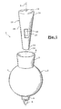
- FIGS 1 and 2 to which reference is now made illustrate a first embodiment of the device 1 according to the invention.
- It comprises a container 2, obtained by extrusion blow molding of a low density polyethylene.
- the container comprises a spherical body 3.
- the spherical body 3 is in communication with a slightly frustoconical end portion 4 ending in an opening 6, closed by a tip 5, the tearing off of which can be obtained by twisting it around the X axis of the end portion 4.
- the spherical body 3 is also in communication with a second end portion 7, diametrically opposite to the end portion 4.
- the end portion 7 is also frustoconical in shape and has a free edge defining an opening 8.
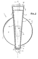
- the device 1 also comprises a tubular insert 10 of frustoconical shape.
- the end 11 of larger section of the insert 10 is closed by a transverse wall 12.
- the other end 13 of the insert 10 is closed by a transverse wall 14 traversed at its center by a spray orifice 15 with the characteristics, in particular dimensional, are chosen according to the characteristics sought for the spray.
- the insert 10 can also be obtained by molding, in particular by roto-molding, a material that is sufficiently flexible to be elastically compressed, such as a polyethylene.
- the diameter of the spray orifice 15 is of the order of 0.5 mm.
- the section of the truncated cone formed by the insert 10 is chosen such that, when the insert 10 is disposed inside the container 2, as shown in FIG. 2, the end of the larger section 11 is tightly against interior walls of the end portion 7 of the container 2.
- the opening 8 is substantially sealingly insulated from the spherical body 3 of the container 2.
- the end of smaller section 13 is sealingly applied against the inner walls of the end portion 4 of the container.
- the product can not exit other than through the spray orifice 15.
- the opening 8 is closed by hot welding, along a weld zone 16.
- Two diametrically opposite windows 17, 18 are formed in the side wall 19 of the insert 10. They are arranged substantially at half axial height of the insert and allow the communication between the volume 20 formed inside the insert 10 and the volume 9 surrounding the insert 10.
- the spray orifice 15 is opposite the orifice 6 of the container 2. It is in communication with the product contained in the device 1 via the windows 17 and 18.
- FIGS. 3A-3C illustrate the main steps of filling the device 1 discussed with reference to FIGS. 1 and 2.
- FIG 3A the container 2 is turned upside down.
- the opening 6 is closed by the tear-off tip 5.
- the product is introduced into the container 2 via the opening 8.
- the insert 10 is introduced into the receptacle 2 until the end wall 14 of the insert abuts against the reduced section portion of the receptacle 2 delimiting the orifice 6. position, the spray orifice 15 is opposite the opening 6, and the end portion 11 of the insert 10 is sealingly applied against the inner walls of the frustoconical portion 7 of the container 2. also position, the end wall 12 of the insert 10 is a few millimeters from the free edge of the container defining the opening 8.
- the product is present both in the annular volume 9 and in the internal volume 20, via the windows 17 and 18.
- the opening 8 is hot-welded along a weld line 16.
- the axial height of the insert 10 with respect to the axial height of the container 2 is chosen so that the two edges defining the opening 8 can be welded together over their entire width, and so that in this position the insert 10 can not substantially move axially inside the container 2.
- FIGS 4A and 4B is shown a detail of an embodiment of a variant of the previous embodiment.
- the inner surface of the wall 14 of the insert 10 is hollowed by three swirling channels 21, 22, 23 extending from the side wall 19 of the insert to the spray orifice 15. Such channels make it possible to accelerate the product in the vicinity of the spray orifice so as to produce a finer spray.
- FIG. 5 the use of the device discussed with reference to FIGS. 1 and 2 is diagrammatically illustrated.
- the product By pressing on the spherical portion 3 of the container 2, the product is pressurized inside the container and is forced out. in the form of a cloud of fine droplets through the spray orifice 15 and the opening 6.
- the pressure on the walls of the container 2 By releasing the pressure on the walls of the container 2, the latter return to their original shape, the volume of product dispensed being compensated by a corresponding volume of air.
- all the content of the device 2 has been sprayed, it can be discarded.
Landscapes
- Engineering & Computer Science (AREA)
- Mechanical Engineering (AREA)
- Containers And Packaging Bodies Having A Special Means To Remove Contents (AREA)
- Sampling And Sample Adjustment (AREA)
- Mechanical Treatment Of Semiconductor (AREA)
- Weting (AREA)
- Investigating, Analyzing Materials By Fluorescence Or Luminescence (AREA)
Claims (17)
- Vorrichtung (1) zum Sprühen eines fluiden Produkts, die einen Behälter (2) mit zusammendrückbaren Wänden aufweist, von dem ein erstes Ende (7) eine erste Öffnung (8) begrenzt, die nach dem Füllen mit dem Produkt verschlossen wird, und von dem ein zweites Ende (4) geschlossen und ausgelegt ist, um vor der ersten Verwendung der Vorrichtung geöffnet zu werden, um eine zweite Öffnung (6) freizugeben, durch die hindurch das Produkt ausgegeben werden kann, wobei die Vorrichtung außerdem einen Einsatz (10) aufweist, der innerhalb des Behälters angeordnet ist, dadurch gekennzeichnet, dass den Einsatz eine Sprühöffnung (15) begrenzt, die mit dem Produkt in Verbindung steht und vor der zweiten Öffnung (6) angeordnet ist, wobei der Einsatz (10) konfiguriert ist, um das Produkt vor dem Verschluss der ersten Öffnung (8) von dieser zu isolieren.
- Vorrichtung (1) nach Anspruch 1, dadurch gekennzeichnet, dass ein Abschnitt (11, 12) des Einsatzes (10), der dazu bestimmt ist, das Produkt von der ersten Öffnung (8) zu isolieren, vor ihrem Verschluss in einem axialen Abstand ungleich Null von der Öffnung angeordnet ist.
- Vorrichtung (1) nach Anspruch 1 oder 2, dadurch gekennzeichnet, dass das Sprühloch (15) nach dem Verschluss der ersten Öffnung (8) innerhalb des Behälters (2) in einer axial festen Stellung ist.
- Vorrichtung (1) nach einem der Ansprüche 1 bis 3, dadurch gekennzeichnet, dass das erste Ende (7) des Behälters sich gegenüber dem zweiten (4) entlang einer Längsachse (X) der Vorrichtung befindet.
- Vorrichtung (1) nach einem der Ansprüche 1 bis 4, dadurch gekennzeichnet, dass der Einsatz (10) ein Innenvolumen (20) bildet, das mit dem Sprühloch (15) in Verbindung steht, wobei ein Außenvolumen (9), das mit dem Innenvolumen in Verbindung steht, zwischen dem Einsatz (10) und dem Behälter (2) begrenzt ist.
- Vorrichtung (1) nach Anspruch 5, dadurch gekennzeichnet, dass der Einsatz (10) in Form eines rohrförmigen Elements konfiguriert ist, dessen erstes Ende (11) geschlossen und dessen zweites, dem ersten gegenüberliegendes Ende (13) vom Sprühloch (15) durchquert wird, wobei mindestens ein Fenster (17, 18) in einer Seitenwand (19) des rohrförmigen Elements ausgebildet ist, um die Verbindung zwischen dem Innenvolumen (20) und dem Außenvolumen (9) zu gewährleisten.
- Vorrichtung (1) nach Anspruch 6, dadurch gekennzeichnet, dass die Seitenwand (19) zwei Fenster (17, 18) aufweist, die einander diametral gegenüberliegend auf der Seitenwand angeordnet sind.
- Vorrichtung (1) nach einem der Ansprüche 1 bis 7, dadurch gekennzeichnet, dass die erste Öffnung (8) von einem kegelstumpfförmigen Abschnitt (7) des Behälters (2) mit zusammendrückbaren Wänden begrenzt wird, dessen Querschnitt in Richtung der ersten Öffnung (8) zunimmt.
- Vorrichtung (1) nach einem der Ansprüche 6 und 8, dadurch gekennzeichnet, dass das rohrförmige Element über mindestens einen Teil (11) seiner Höhe, der mit dem kegelstumpfförmigen Abschnitt (7) des Behälters in Eingriff steht, kegelstumpfförmig ist, um sich dicht darauf aufzulegen.
- Vorrichtung (1) nach Anspruch 9, dadurch gekennzeichnet, dass der Einsatz (10) über seine ganze Höhe kegelstumpfförmig ist.
- Vorrichtung (1) nach einem der Ansprüche 1 bis 10, dadurch gekennzeichnet, dass die erste Öffnung (8) von einer Schweißnaht, insbesondere einer Wärme- oder Ultraschall-Schweißnaht (16), oder durch Kleben verschlossen wird.
- Vorrichtung (1) nach einem der vorhergehenden Ansprüche, dadurch gekennzeichnet, dass der Behälter (2) durch Formen, insbesondere durch Extrusionsblasen, erhalten wird, wobei die zweite Öffnung (6) von einem Abschnitt (5) verschlossen wird, der aus einem Stück mit dem Behälter geformt wird abreißbar ist, insbesondere als Reaktion auf eine Verdrehung um die Achse (X) der zweiten Öffnung (6).
- Vorrichtung (1) nach einem der Ansprüche 1 bis 12, dadurch gekennzeichnet, dass der Behälter (2) aus einem thermoplastischen Material geformt wird, insbesondere einem Polyethylen niedriger Dichte.
- Vorrichtung (1) nach einem der vorhergehenden Ansprüche, dadurch gekennzeichnet, dass der Behälter (2) zwischen dem ersten (7) und dem zweiten Ende (4) einen im Wesentlichen kugelförmigen Bereich (3) aufweist.
- Vorrichtung (1) nach einem der vorhergehenden Ansprüche, dadurch gekennzeichnet, dass das Sprühloch (15) in einer Endwand (14) des Einsatzes (10) ausgebildet ist, wobei in eine Innenfläche der Wand (14) mehrere Wirbelkanäle (21, 22, 23) gebohrt sind, die am Sprühloch (15) münden.
- Verwendung einer Vorrichtung (1) nach einem der vorhergehenden Ansprüche zur Verpackung und zur Ausgabe einer Probedosis eines kosmetischen Produkts, insbesondere eines Parfüms.
- Verfahren zur Verpackung eines fluiden Produkts, dadurch gekennzeichnet, dass es die folgenden Schritte aufweist:a) Einführen des Produkts in einen Behälter mit zusammendrückbaren Wänden (2) durch eine erste Öffnung (8), die von einem ersten Ende (7) des Behälters gebildet wird, wobei ein zweites Ende (4) des Behälters geschlossen und ausgelegt ist, um vor der ersten Benutzung der Vorrichtung geöffnet zu werden, um eine zweite Öffnung (6) freizugeben, durch die hindurch das Produkt ausgegeben werden kann;b) Einführen eines Einsatzes (10) durch die erste Öffnung (8), der ein Sprühloch (15) begrenzt, das mit dem Produkt im Inneren des Behälters in Verbindung steht und vor der zweiten Öffnung (6) angeordnet ist, wobei der Einsatz (10) so konfiguriert ist, dass er das Produkt vor dem Verschließen der ersten Öffnung (8) von dieser isoliert; undc) dichtes Verschließen der ersten Öffnung (8).
Applications Claiming Priority (2)
| Application Number | Priority Date | Filing Date | Title |
|---|---|---|---|
| FR0102164A FR2820993B1 (fr) | 2001-02-16 | 2001-02-16 | Dispositif de pulverisation du type echantillon |
| FR0102164 | 2001-02-16 |
Publications (2)
| Publication Number | Publication Date |
|---|---|
| EP1232798A1 EP1232798A1 (de) | 2002-08-21 |
| EP1232798B1 true EP1232798B1 (de) | 2006-08-16 |
Family
ID=8860127
Family Applications (1)
| Application Number | Title | Priority Date | Filing Date |
|---|---|---|---|
| EP02290147A Expired - Lifetime EP1232798B1 (de) | 2001-02-16 | 2002-01-21 | Sprühvorrichtung für Probenmengen |
Country Status (8)
| Country | Link |
|---|---|
| US (1) | US6755357B2 (de) |
| EP (1) | EP1232798B1 (de) |
| JP (1) | JP3566259B2 (de) |
| AT (1) | ATE336302T1 (de) |
| CA (1) | CA2371110C (de) |
| DE (1) | DE60213893T2 (de) |
| ES (1) | ES2269622T3 (de) |
| FR (1) | FR2820993B1 (de) |
Families Citing this family (7)
| Publication number | Priority date | Publication date | Assignee | Title |
|---|---|---|---|---|
| JP2003073229A (ja) * | 2001-09-03 | 2003-03-12 | Asahi Kasei Corp | セルロースを含有するスプレー剤 |
| NZ528981A (en) * | 2003-10-16 | 2005-03-24 | Andrew Leo Haynes | Cladding system related to sealing buidling structures |
| US8640920B2 (en) * | 2006-12-20 | 2014-02-04 | Momentive Performance Materials Inc. | Method of forming and filling a pouch |
| CN102026881B (zh) * | 2008-06-11 | 2014-07-02 | 花王株式会社 | 挤压式容器 |
| US10301057B2 (en) * | 2016-07-11 | 2019-05-28 | Calibre Closures Llc | Dispensing container with internal squeeze limiting member |
| KR102014485B1 (ko) * | 2016-07-19 | 2019-08-26 | 배민준 | 액상 내용물을 원하는 양만큼씩 유출시킬 수 있는 용기 |
| US11225370B2 (en) | 2020-01-09 | 2022-01-18 | Sonoco Development, Inc. | Portion control dispenser |
Family Cites Families (16)
| Publication number | Priority date | Publication date | Assignee | Title |
|---|---|---|---|---|
| US54394A (en) * | 1866-05-01 | Improvement in oilers | ||
| US644703A (en) * | 1898-09-28 | 1900-03-06 | Mathew James Buckley | Moistening apparatus. |
| US2080864A (en) * | 1935-06-07 | 1937-05-18 | Hilts Harold Capron | Insecticide sprayer |
| US3412907A (en) | 1967-03-07 | 1968-11-26 | William J. Faso | Perfume container and sprayer |
| US3471064A (en) * | 1968-06-07 | 1969-10-07 | Leeds & Micallef | Foam generating and dispensing device |
| US3897005A (en) | 1972-11-13 | 1975-07-29 | George Reiner | Convenience spray dispensing packet |
| SE370177B (de) * | 1973-03-22 | 1974-10-07 | B Nilsson | |
| JPS52111913A (en) | 1976-03-17 | 1977-09-20 | Taishiyou Garasu Kk | Method of charging glass material into electric melting furnace and electric melting furnace for execution of sald process |
| SE7905979L (sv) | 1978-12-15 | 1980-06-16 | Panpack Ag | Forpackning for upptagning och sprutning av sma vetskemengder |
| US4266445A (en) | 1979-03-22 | 1981-05-12 | Eaton Corporation | Locking differential |
| JPS6482186A (en) | 1987-09-24 | 1989-03-28 | Toshiba Corp | Data supplementing and processing system |
| JP2922935B2 (ja) | 1989-08-11 | 1999-07-26 | 東興薬品工業株式会社 | 粘稠液用鼻孔内噴霧容器の使捨てアダプタ |
| DE4136826A1 (de) | 1991-11-08 | 1993-05-13 | Pfeiffer Erich Gmbh & Co Kg | Austragvorrichtung fuer medien |
| US5497910A (en) * | 1994-05-05 | 1996-03-12 | Allergan, Inc. | Dropwise liquid dispensing system particularly suitable for liquids having low surface tension |
| JP3198866B2 (ja) | 1995-03-24 | 2001-08-13 | 住友金属工業株式会社 | Mos集積回路の製造方法 |
| FR2778639B1 (fr) | 1998-05-18 | 2000-07-28 | Valois Sa | Dispositif de pulverisation du type echantillon |
-
2001
- 2001-02-16 FR FR0102164A patent/FR2820993B1/fr not_active Expired - Fee Related
-
2002
- 2002-01-21 AT AT02290147T patent/ATE336302T1/de not_active IP Right Cessation
- 2002-01-21 EP EP02290147A patent/EP1232798B1/de not_active Expired - Lifetime
- 2002-01-21 ES ES02290147T patent/ES2269622T3/es not_active Expired - Lifetime
- 2002-01-21 DE DE60213893T patent/DE60213893T2/de not_active Expired - Fee Related
- 2002-02-05 CA CA002371110A patent/CA2371110C/fr not_active Expired - Fee Related
- 2002-02-15 US US10/075,198 patent/US6755357B2/en not_active Expired - Fee Related
- 2002-02-18 JP JP2002040616A patent/JP3566259B2/ja not_active Expired - Fee Related
Also Published As
| Publication number | Publication date |
|---|---|
| JP2002347860A (ja) | 2002-12-04 |
| CA2371110C (fr) | 2005-04-26 |
| CA2371110A1 (fr) | 2002-08-16 |
| US6755357B2 (en) | 2004-06-29 |
| FR2820993A1 (fr) | 2002-08-23 |
| ES2269622T3 (es) | 2007-04-01 |
| ATE336302T1 (de) | 2006-09-15 |
| DE60213893D1 (de) | 2006-09-28 |
| US20020117519A1 (en) | 2002-08-29 |
| FR2820993B1 (fr) | 2003-10-31 |
| EP1232798A1 (de) | 2002-08-21 |
| JP3566259B2 (ja) | 2004-09-15 |
| DE60213893T2 (de) | 2007-01-04 |
Similar Documents
| Publication | Publication Date | Title |
|---|---|---|
| EP1270444B1 (de) | Vorrichtung zur gleichzeitigen Abgabe getrennt verpackter Produkte | |
| EP1279607B1 (de) | Sprühvorrichtung für ein flüssiges Mittel | |
| CA2245988C (fr) | Ensemble de conditionnement et de distribution bi-produits | |
| CA2348105C (fr) | Embout doseur et ensemble de distribution equipe d'un tel embout | |
| EP0952090B1 (de) | Dosieraufsatz | |
| FR2764868A1 (fr) | Dispositif de conditionnement d'un produit a plusieurs composantes devant etre stockees separement et melangees juste avant l'emploi du produit | |
| CA2389874C (fr) | Dispositif pour la pulverisation d'un produit, notamment sous forme de dose echantillon | |
| EP1270428A1 (de) | Vorrichtung zum Zerstäuben eines Produktes, insbesondere in Form von Probedosierung | |
| FR2804666A1 (fr) | Distributeur pour le stockage d'au moins deux composants et la distribution selective soit d'un constituant seul, soit de leur melange, et procede pour sa mise en oeuvre | |
| FR2750678A1 (fr) | Dispositif de distribution biphasique d'une dose unique | |
| EP1232798B1 (de) | Sprühvorrichtung für Probenmengen | |
| CA2201637A1 (fr) | Dispositif de conditionnement et d'application d'un produit capillaire | |
| FR3098735A1 (fr) | Distributeur de fluide | |
| CA2383305C (fr) | Dispositif pour la pulverisation d'un produit, notamment sous forme d'une dose echantillon dudit produit | |
| FR2588490A1 (fr) | Diffuseur en matiere plastique moulee pour la diffusion de produits sous forme de mousse, adaptable sur recipients pressurises | |
| FR3098736A1 (fr) | Distributeur de fluide | |
| FR2773443A1 (fr) | Atomiseur rechargeable de sac a main | |
| FR2643615A1 (fr) | Ensemble permettant de conditionner separement deux produits pouvant presenter des viscosites differentes et de les distribuer simultanement en doses egales en volume | |
| FR2885495A1 (fr) | Ensemble de conditionnement et de distribution d'un produit | |
| EP1757526B1 (de) | Sprühvorrichtung für flüssiges Produkt | |
| FR2561210A1 (fr) | Dispositif permettant de distribuer une substance liquide | |
| FR2753438A1 (fr) | Conditionnement pour le stockage et le melange d'un produit a deux composantes devant etre stockees separement et melangees juste avant l'emploi du produit | |
| FR2731684A1 (fr) | Dispositif de stockage et de distribution d'un produit, tel un produit cosmetique ou un parfum | |
| FR2846305A1 (fr) | Distributeur de produit fluide. | |
| FR2896386A1 (fr) | Vaporisateur creux deformable |
Legal Events
| Date | Code | Title | Description |
|---|---|---|---|
| PUAI | Public reference made under article 153(3) epc to a published international application that has entered the european phase |
Free format text: ORIGINAL CODE: 0009012 |
|
| AK | Designated contracting states |
Kind code of ref document: A1 Designated state(s): AT BE CH CY DE DK ES FI FR GB GR IE IT LI LU MC NL PT SE TR |
|
| AX | Request for extension of the european patent |
Free format text: AL;LT;LV;MK;RO;SI |
|
| 17P | Request for examination filed |
Effective date: 20030221 |
|
| AKX | Designation fees paid |
Designated state(s): AT BE CH CY DE DK ES FI FR GB GR IE IT LI LU MC NL PT SE TR |
|
| GRAP | Despatch of communication of intention to grant a patent |
Free format text: ORIGINAL CODE: EPIDOSNIGR1 |
|
| GRAS | Grant fee paid |
Free format text: ORIGINAL CODE: EPIDOSNIGR3 |
|
| GRAA | (expected) grant |
Free format text: ORIGINAL CODE: 0009210 |
|
| AK | Designated contracting states |
Kind code of ref document: B1 Designated state(s): AT BE CH CY DE DK ES FI FR GB GR IE IT LI LU MC NL PT SE TR |
|
| PG25 | Lapsed in a contracting state [announced via postgrant information from national office to epo] |
Ref country code: IE Free format text: LAPSE BECAUSE OF FAILURE TO SUBMIT A TRANSLATION OF THE DESCRIPTION OR TO PAY THE FEE WITHIN THE PRESCRIBED TIME-LIMIT Effective date: 20060816 Ref country code: FI Free format text: LAPSE BECAUSE OF FAILURE TO SUBMIT A TRANSLATION OF THE DESCRIPTION OR TO PAY THE FEE WITHIN THE PRESCRIBED TIME-LIMIT Effective date: 20060816 Ref country code: IT Free format text: LAPSE BECAUSE OF FAILURE TO SUBMIT A TRANSLATION OF THE DESCRIPTION OR TO PAY THE FEE WITHIN THE PRESCRIBED TIME-LIMIT;WARNING: LAPSES OF ITALIAN PATENTS WITH EFFECTIVE DATE BEFORE 2007 MAY HAVE OCCURRED AT ANY TIME BEFORE 2007. THE CORRECT EFFECTIVE DATE MAY BE DIFFERENT FROM THE ONE RECORDED. Effective date: 20060816 Ref country code: AT Free format text: LAPSE BECAUSE OF FAILURE TO SUBMIT A TRANSLATION OF THE DESCRIPTION OR TO PAY THE FEE WITHIN THE PRESCRIBED TIME-LIMIT Effective date: 20060816 Ref country code: NL Free format text: LAPSE BECAUSE OF FAILURE TO SUBMIT A TRANSLATION OF THE DESCRIPTION OR TO PAY THE FEE WITHIN THE PRESCRIBED TIME-LIMIT Effective date: 20060816 |
|
| REG | Reference to a national code |
Ref country code: GB Ref legal event code: FG4D Free format text: NOT ENGLISH |
|
| REG | Reference to a national code |
Ref country code: CH Ref legal event code: EP |
|
| REG | Reference to a national code |
Ref country code: IE Ref legal event code: FG4D Free format text: LANGUAGE OF EP DOCUMENT: FRENCH |
|
| REF | Corresponds to: |
Ref document number: 60213893 Country of ref document: DE Date of ref document: 20060928 Kind code of ref document: P |
|
| PG25 | Lapsed in a contracting state [announced via postgrant information from national office to epo] |
Ref country code: SE Free format text: LAPSE BECAUSE OF FAILURE TO SUBMIT A TRANSLATION OF THE DESCRIPTION OR TO PAY THE FEE WITHIN THE PRESCRIBED TIME-LIMIT Effective date: 20061116 Ref country code: DK Free format text: LAPSE BECAUSE OF FAILURE TO SUBMIT A TRANSLATION OF THE DESCRIPTION OR TO PAY THE FEE WITHIN THE PRESCRIBED TIME-LIMIT Effective date: 20061116 |
|
| GBT | Gb: translation of ep patent filed (gb section 77(6)(a)/1977) |
Effective date: 20061026 |
|
| PG25 | Lapsed in a contracting state [announced via postgrant information from national office to epo] |
Ref country code: PT Free format text: LAPSE BECAUSE OF FAILURE TO SUBMIT A TRANSLATION OF THE DESCRIPTION OR TO PAY THE FEE WITHIN THE PRESCRIBED TIME-LIMIT Effective date: 20070116 |
|
| PG25 | Lapsed in a contracting state [announced via postgrant information from national office to epo] |
Ref country code: MC Free format text: LAPSE BECAUSE OF NON-PAYMENT OF DUE FEES Effective date: 20070131 Ref country code: CH Free format text: LAPSE BECAUSE OF NON-PAYMENT OF DUE FEES Effective date: 20070131 Ref country code: LI Free format text: LAPSE BECAUSE OF NON-PAYMENT OF DUE FEES Effective date: 20070131 |
|
| NLV1 | Nl: lapsed or annulled due to failure to fulfill the requirements of art. 29p and 29m of the patents act | ||
| REG | Reference to a national code |
Ref country code: IE Ref legal event code: FD4D |
|
| REG | Reference to a national code |
Ref country code: ES Ref legal event code: FG2A Ref document number: 2269622 Country of ref document: ES Kind code of ref document: T3 |
|
| PLBE | No opposition filed within time limit |
Free format text: ORIGINAL CODE: 0009261 |
|
| STAA | Information on the status of an ep patent application or granted ep patent |
Free format text: STATUS: NO OPPOSITION FILED WITHIN TIME LIMIT |
|
| 26N | No opposition filed |
Effective date: 20070518 |
|
| REG | Reference to a national code |
Ref country code: CH Ref legal event code: PL |
|
| BERE | Be: lapsed |
Owner name: L'OREAL Effective date: 20070131 |
|
| PG25 | Lapsed in a contracting state [announced via postgrant information from national office to epo] |
Ref country code: BE Free format text: LAPSE BECAUSE OF NON-PAYMENT OF DUE FEES Effective date: 20070131 |
|
| PG25 | Lapsed in a contracting state [announced via postgrant information from national office to epo] |
Ref country code: GR Free format text: LAPSE BECAUSE OF FAILURE TO SUBMIT A TRANSLATION OF THE DESCRIPTION OR TO PAY THE FEE WITHIN THE PRESCRIBED TIME-LIMIT Effective date: 20061117 |
|
| PGFP | Annual fee paid to national office [announced via postgrant information from national office to epo] |
Ref country code: ES Payment date: 20080218 Year of fee payment: 7 |
|
| PGFP | Annual fee paid to national office [announced via postgrant information from national office to epo] |
Ref country code: DE Payment date: 20080117 Year of fee payment: 7 Ref country code: GB Payment date: 20080116 Year of fee payment: 7 |
|
| PG25 | Lapsed in a contracting state [announced via postgrant information from national office to epo] |
Ref country code: LU Free format text: LAPSE BECAUSE OF NON-PAYMENT OF DUE FEES Effective date: 20070121 Ref country code: CY Free format text: LAPSE BECAUSE OF FAILURE TO SUBMIT A TRANSLATION OF THE DESCRIPTION OR TO PAY THE FEE WITHIN THE PRESCRIBED TIME-LIMIT Effective date: 20060816 |
|
| PGFP | Annual fee paid to national office [announced via postgrant information from national office to epo] |
Ref country code: IT Payment date: 20090127 Year of fee payment: 8 |
|
| GBPC | Gb: european patent ceased through non-payment of renewal fee |
Effective date: 20090121 |
|
| PG25 | Lapsed in a contracting state [announced via postgrant information from national office to epo] |
Ref country code: TR Free format text: LAPSE BECAUSE OF FAILURE TO SUBMIT A TRANSLATION OF THE DESCRIPTION OR TO PAY THE FEE WITHIN THE PRESCRIBED TIME-LIMIT Effective date: 20060816 |
|
| PG25 | Lapsed in a contracting state [announced via postgrant information from national office to epo] |
Ref country code: DE Free format text: LAPSE BECAUSE OF NON-PAYMENT OF DUE FEES Effective date: 20090801 |
|
| PGFP | Annual fee paid to national office [announced via postgrant information from national office to epo] |
Ref country code: FR Payment date: 20090113 Year of fee payment: 8 |
|
| PG25 | Lapsed in a contracting state [announced via postgrant information from national office to epo] |
Ref country code: GB Free format text: LAPSE BECAUSE OF NON-PAYMENT OF DUE FEES Effective date: 20090121 |
|
| REG | Reference to a national code |
Ref country code: ES Ref legal event code: FD2A Effective date: 20090122 |
|
| PG25 | Lapsed in a contracting state [announced via postgrant information from national office to epo] |
Ref country code: ES Free format text: LAPSE BECAUSE OF NON-PAYMENT OF DUE FEES Effective date: 20090122 |
|
| REG | Reference to a national code |
Ref country code: FR Ref legal event code: ST Effective date: 20100930 |
|
| PG25 | Lapsed in a contracting state [announced via postgrant information from national office to epo] |
Ref country code: FR Free format text: LAPSE BECAUSE OF NON-PAYMENT OF DUE FEES Effective date: 20100201 |
|
| PG25 | Lapsed in a contracting state [announced via postgrant information from national office to epo] |
Ref country code: IT Free format text: LAPSE BECAUSE OF NON-PAYMENT OF DUE FEES Effective date: 20100121 |