EP1231769A2 - Mehrstrahl-Abtastvorrichtung zur Abtastung eines fotoempfindlichen Materials mit einem Multi-Spot-Array sowie Verfahren zur Korrektur der Position von dadurch erzeugten Bildpunkten - Google Patents
Mehrstrahl-Abtastvorrichtung zur Abtastung eines fotoempfindlichen Materials mit einem Multi-Spot-Array sowie Verfahren zur Korrektur der Position von dadurch erzeugten Bildpunkten Download PDFInfo
- Publication number
- EP1231769A2 EP1231769A2 EP01129508A EP01129508A EP1231769A2 EP 1231769 A2 EP1231769 A2 EP 1231769A2 EP 01129508 A EP01129508 A EP 01129508A EP 01129508 A EP01129508 A EP 01129508A EP 1231769 A2 EP1231769 A2 EP 1231769A2
- Authority
- EP
- European Patent Office
- Prior art keywords
- fiber
- laser
- scanning device
- beam scanning
- photosensitive material
- Prior art date
- Legal status (The legal status is an assumption and is not a legal conclusion. Google has not performed a legal analysis and makes no representation as to the accuracy of the status listed.)
- Withdrawn
Links
Images



Classifications
-
- H—ELECTRICITY
- H04—ELECTRIC COMMUNICATION TECHNIQUE
- H04N—PICTORIAL COMMUNICATION, e.g. TELEVISION
- H04N1/00—Scanning, transmission or reproduction of documents or the like, e.g. facsimile transmission; Details thereof
- H04N1/04—Scanning arrangements, i.e. arrangements for the displacement of active reading or reproducing elements relative to the original or reproducing medium, or vice versa
-
- G—PHYSICS
- G02—OPTICS
- G02B—OPTICAL ELEMENTS, SYSTEMS OR APPARATUS
- G02B6/00—Light guides; Structural details of arrangements comprising light guides and other optical elements, e.g. couplings
- G02B6/24—Coupling light guides
- G02B6/42—Coupling light guides with opto-electronic elements
- G02B6/4201—Packages, e.g. shape, construction, internal or external details
- G02B6/4219—Mechanical fixtures for holding or positioning the elements relative to each other in the couplings; Alignment methods for the elements, e.g. measuring or observing methods especially used therefor
- G02B6/422—Active alignment, i.e. moving the elements in response to the detected degree of coupling or position of the elements
- G02B6/4221—Active alignment, i.e. moving the elements in response to the detected degree of coupling or position of the elements involving a visual detection of the position of the elements, e.g. by using a microscope or a camera
-
- G—PHYSICS
- G02—OPTICS
- G02B—OPTICAL ELEMENTS, SYSTEMS OR APPARATUS
- G02B6/00—Light guides; Structural details of arrangements comprising light guides and other optical elements, e.g. couplings
- G02B6/24—Coupling light guides
- G02B6/42—Coupling light guides with opto-electronic elements
- G02B6/4201—Packages, e.g. shape, construction, internal or external details
- G02B6/4249—Packages, e.g. shape, construction, internal or external details comprising arrays of active devices and fibres
- G02B6/425—Optical features
-
- H—ELECTRICITY
- H04—ELECTRIC COMMUNICATION TECHNIQUE
- H04N—PICTORIAL COMMUNICATION, e.g. TELEVISION
- H04N2201/00—Indexing scheme relating to scanning, transmission or reproduction of documents or the like, and to details thereof
- H04N2201/04—Scanning arrangements
- H04N2201/0402—Arrangements not specific to a particular one of the scanning methods covered by groups H04N1/04 - H04N1/207
- H04N2201/046—Actively compensating for disturbances, e.g. vibrations
Definitions
- the invention relates to the field of electronic reproduction technology, in particular on the laser engraving of printing plates but also on laser exposure of film with a multi-spot array. More particularly, the invention relates on the one hand a multi-beam scanning device for scanning a photosensitive Materials with a multi-spot array, comprising a plurality of Fiber laser fiber exits, each detachable in a holder of a holder Multi-beam scanning device are used, as well as a method to correct the position of pixels of a multi-spot array, which is shown by imaging a plurality of fiber laser fiber exits on one moved with respect thereto photosensitive material and by interruption, distraction and / or Intensity modulation of laser beams emerging from the fiber exits is produced.
- the Multi-beam scanners or laser processing heads of those used Laser imageseters equipped with fiber lasers the fiber exits arranged side by side and are aligned to the drum or pressure plate so that the the latter is scanned with a linear multi-spot array.
- the multi-beam scanners or laser processing heads further comprise an optical system to map the fiber exits and to focus the laser beam on the printing plate surface, as well as devices for selective interruption, Deflection and / or intensity modulation of the individual laser beams.
- Such a multi-beam scanning device is in the as yet unpublished German patent application DE 100 24 456.4 described by the applicant.
- the fiber exits equipped with micro or collimator lenses are so in Use precision bores or V-shaped grooves in a bracket, that they have the desired orientation. Due to manufacturing tolerances in the manufacture of fiber exits, in the fitting of the lenses and However, it does occur in the manufacture of the holder or the fiber exit recordings in practice to deviations in direction of the laser beam from their intended optical axis, which is in the form of position errors, i.e. deflections individual pixels of the multi-spot array in any direction from their Target position, make it noticeable. As a result of their recurrence during These position errors lead to the scanning when processing printing plates or disturbing patterns when recording images on a film and thus a deterioration in quality.
- the largest position deviations are usually caused by so-called pointing errors which causes fiber exits, i.e. the angular deviation of a radiated one Laser beam in relation to a cylinder axis for assembly of the fiber exit and the collimator lens serving capillary tube.
- the object of the invention is a multi-beam scanning device and to provide a correction method of the type mentioned at the outset, with which multi-spot arrays can be created with high precision, so that when using the photosensitive material as a template, none disturbing patterns are visible on the end product.
- the invention is based on the idea of matching angular alignment all pixels of the multi-spot array in relation to their respective Target position is the prerequisite for electronic adjustment by distraction and / or to create delay time of the laser beam with of all the laser beams so far in the same direction, namely in Direction of their target position, be moved until their distance to this target position Is zero or almost zero.
- the complementary alignment devices of a fiber exit can and the holder from a printed or painted on the fiber exit Color markers exist that are in a certain direction, for example points vertically upwards, and with a corresponding marking of the holder is in alignment as soon as the fiber exit into the Recording is used.
- the fiber exits are preferably aligned however, from an element projecting radially beyond the fiber exit, the positively engaged with a complementary element of the bracket can, if the fiber exit in the recording the previously specified Has angle of rotation.
- the more time-consuming determination of the pointing error of each fiber exit and the then determining the alignment device in the correct rotational position the fiber exit can take place at the manufacturer of the multi-beam scanning device, where suitable adjustment devices are available.
- These preferably point a holder corresponding to the holder of the multi-beam scanning device with a fiber exit recording in which the fiber exits are inserted one after the other and be rotated around its axis. Describes when the laser is switched on a pixel generated on a position detector of the adjusting device a circular path, the larger the pointing error, the larger the diameter of the fiber exit.
- the Alignment device attached to the fiber exit in a fixed angular relationship, and in such a way that it points in the same direction for all adjusted fiber exits.
- each pixel to reduce its distance from the respective target position by deflecting the laser beam preferably with the help of a beam path between the fiber exit and the photosensitive Material arranged acousto-optical modulator, which in many Imagesetters already exist and there for interruption or distraction and / or for intensity modulation of the laser beam.
- Also reducing the distance of a pixel from its target position by delaying the time of impact of the laser beam can with the help of the acousto-optic modulator can be done by interrupting or Deflection and / or to modulate the intensity of the laser beam at the acousto-optic modulator applied voltage signals with a distance of the respective pixel from the time delay taking into account the target position supplies.
- one of the two would be to correct the point errors of the fiber exits
- Alternatives mentioned, namely deflection of the laser beam or Delay in the time of impact of the laser beam is sufficient if the angle of rotation of the fiber exits in the holder is determined so that the pixels by the distraction or by the time delay exactly in the direction of theirs Target position to be shifted.
- the distances between the pixels and their target position both by distraction and by Reduce the time delay of the laser beam, taking the two measures alternately to be carried out an iterative approach to the to effect respective target position.
- This complies with that for film exposure or laser engraving used a drum imager Multi-spot arrays due to the deflection or the time delay of the laser beam in the acousto-optic modulator in one essentially two to each other perpendicular directions is shifted so that the approximation to the Desired position can be done in gradually decreasing steps.
- the device (1) shown in Fig. 1 for laser engraving of flexographic printing plates consists essentially of a rotatable between two side brackets clamped drum (2), on the peripheral surface of which to be processed Flexo printing plates (3) are clamped, a rotary drive (not shown) for rotating the drum (2) and a pressure plate (3), a on guides (4) in the axial direction of the drum (2) and the pressure plate (3) movable carriage (5), a laser processing head mounted on the carriage (5) (6) by a bundle of eight fiber optics (7) with a Multi-beam YAG laser (not visible) in a stationary lower part (8) of the device (1) is connected, and a control panel (9), which is also on guides (10) is movable in the axial direction along the drum (2).
- a lower carrier layer (11) made of metal or plastic, preferably a polyester film, one applied to the top of the carrier layer (11)
- Photopolymer layer (12) containing unsaturated monomers and elastomeric binders that become long chain when exposed to UVA light Polymers are crosslinked, as well as one on top of the photopolymer layer (12) applied, UV-sensitive, laser-sensitive Layer (13).
- the flexographic printing plate (3) is made according to a predetermined one Dot grid focused on the laser-sensitive layer (13) at the same time as eight Laser beams (14) scanned, as in Fig. 2 by two of the laser beams (14) shown schematically.
- the ablation is thermal Process in which the laser-sensitive layer (13) forms punctiform Openings evaporated to the photopolymer layer (12) and thereby removed becomes. Subsequent irradiation with UV light hardens the photopolymer layer (12) under the openings and is unlike the other areas not washed out during subsequent development.
- the wavelength the laser radiation emitted by the YAG lasers is in the infrared range, while the photopolymer is sensitive in the UV range, so when scanning it with the laser beams (14) is not influenced by the laser light.
- the flexographic printing plate (3) is scanned in a predetermined dot pattern, that of a raster image processor (not shown) from the onto the printing plate (3) Font or image information to be transmitted in the form of digital pixel data is produced.
- the 8-channel laser processing head (6) essentially consists of a holder (18) for the fiber exits (19) of the eight fiber optics (7), a linear AOM array (20) for intensity modulation of the individual laser beams (14), and one consisting of three lenses (L1, L2 and L3) f- ⁇ - optical system (22), with the the fiber exits (19) as a linear multi-spot array telecentrically on the surface the pressure plate (3).
- the fiber exits (19) have a Angular distance of about 10 mrad in a fan shape next to each other in a V-shape Receiving grooves (23) of the bracket (18) used so that the in one plane (E) lying optical axes (24) of those emerging from the fiber exits (19) Laser beam bundle (14) after passing through the AOM array (20) in one Cut the entrance pupil (EP) of the optical system (22), as shown schematically in FIG. 2 shown with larger angular distances when used to map the fiber exits (19) on the pressure plate (3) in the AOMs (21) of the AOM array (20) in the 1st order have been distracted.
- a bracket (18) mounted on a carrier (28) has a holder facing away from the drum (2) rear fastening part (29) for the fiber exits (19) in which this are clamped for strain relief, and one facing the drum (2) front receiving part (30) in which each of the fiber exits (19) by a spring-loaded Stamp (31) is pressed down into the associated receiving groove (23).
- the fiber exits (19) essentially consist of a cylindrical capillary tube (26), in one end of which the end of one of the fiber optics (7) is inserted and the other end as a holder for a collimator or microlens (25) which bundles the laser beams emerging from the fiber exit (19).
- the structure of the AOMs (21) corresponds to known acousto-optical ones Modulators and comprise one for the laser beam (14) transparent crystal (32) and a piezoelectric transducer (33) (only for Part shown) that emits ultrasonic waves into the crystal (32) when a voltage signal is applied to the converter (33).
- the laser beam (14) on the generated by the transducer (33) Ultrasound waves diffracted, depending on the respective amplitude of the voltage signal either as a 1st order light beam to the entrance pupil (EP) of the optical system (22) and from there to the flexographic printing plate (3) or is hidden as a 0th order light beam, depending on whether the laser sensitive Layer (13) of the pressure plate (3) removed at the corresponding point to be or not.
- the amplitude of the voltage signal is based on of the pixel data controlled.
- the AOM array (20) is the laser beam at one point in the beam path (14) arranged at the distances of the individual AOMs (21) the distances correspond to the associated laser beam (14) and is aligned that the laser beam (14) in each case approximately at the Bragg angle in an optical entry surface of the AOMs (21) enter. About diffraction efficiency to improve the AOMs (21) and the laser beams (14) if possible.
- the transducers (33) are to be passed through the AOMs (21) without vignetting. on the individual AOMs (21) each parallel to the optical axis (24) of the passing through Laser beam (14) aligned.
- the AOM array (20) and the entrance pupil (EP) of the optical system (22) are each at such a distance from the waist T of the laser beam (14) (FIG. 5) that both the AOMs (21) and the Entry pupil (EP) lie within the Rayleigh distance, within which the diameter of the laser beam (14) increases to d 0 x ⁇ 2.
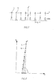
- those emerging from the microlenses (25) of the fiber exits (19) Laser beams (14) parallel to the respective cylinder axes of the capillary tubes (26), and the receiving grooves (23) have the same angular distances and heights on, whereby the fiber exits (19) on the pressure plate (3) theoretically as ideal Multi-spot array are depicted, the pixels of which are all on one axis (X) lie and have the same distances, as shown in Fig. 7.
- the fiber exits (19) of 10 mrad and a distance / diameter ratio 8 to 1 in the holder (18) result for the impact points (15) of the eight laser beams (14) on the laser sensitive layer (13) and thus for neighboring pixels of the linear multi-spot array, center distances Ix of about 160 ⁇ m and spot diameter d (50%) of about 20 ⁇ m.
- the multi-spot array is rarely ideal, on the one hand because of the laser beams (14) emerging from the microlenses (25) because of so-called Pointing errors of the fiber exits (19) more or less large angular deviations from the cylinder axis of the capillary tube (26), and to the other because the receiving grooves (23) of the holder (18) due to manufacturing tolerances are not always equidistant and at the same height.
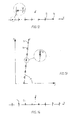
- the pointing errors at least some of the pixels of the multi-spot array point deviations from the target position on the printing plate, as in FIG. 9 somewhat exaggerated, usually both the spacing of the pixels from their target positions (shown as white circles) as well as the directions or angular orientations of the pixels with respect to their target positions are different.
- the invention First all fiber exits (19) mechanically into the grooves (23) used that all pixels of the multi-spot array in relation to their Target position have essentially the same angular orientation as in the Figures 10 and 12 shown using two examples, before then electronically the distances of the individual pixels from their target position, if necessary by a corresponding deflection of the laser beam (14) in the AOMs (21) and / or by a corresponding delay in the time of impact the laser beam (14) on the printing plate (3) can be reduced.
- the two electronic correction steps can each be done individually or alternately be carried out successively until the distances are zero or almost Are reduced to zero.
- the same angular orientation here means that the direction vectors of the respective Target position to the respective pixel, the same angle ( ⁇ ) with the through all target positions (X) and preferably the same Show signs. If the angular error of the laser beam (14) is proportional are small and the bandwidth of the AOMs (21) is sufficient to handle the errors essentially already by deflecting the laser beam (14) in To correct AOM (21), the angles ( ⁇ ) are preferably chosen such that as in the multi-spot array shown in FIG. 10, they correspond to 90 ° be.
- the angles ( ⁇ ) preferably selected so that it, as in the multi-spot array shown in FIG each 7.13 ° (corresponding to 90 ° - arctan lx / d (50%)), so that the deviations from the target position essentially by a corresponding adjusted time delay of the voltage signals can be corrected.
- This pixel describes the rotation the fiber exits a circular path, the larger the diameter, the larger is the pointing error of the fiber exit (19).
- the pixels are related to the axis or in relation to a corresponding coordinate system of the Adjusting device have a desired angular orientation, for example vertically above the axis, a mark is made on the fiber exit (19) attached that corresponds to this angular orientation and for example also points upwards. After determining the pointing errors of all fiber exits (19) these are inserted into the receiving grooves (23) of the holder (18), that all markings point in the same direction, for example again up.
- the fiber exits (19) shown in FIG. 4 are also included a flag (35) which projects radially beyond the capillary tube (26) and which the direction of the pointing error of the fiber exit (19) or a defined one Angular distance from this indicates.
- the flag (35) is part of one on the capillary tube (26) slidable rotatable cylinder sleeve (36) in the adjusting device according to the direction of the pointing error on the capillary tube (26) is stuck.
- the flag (35) has an alignment notch at its upper end (not visible) into the one above the fiber exit (19) in the holder (18) inserted, to the respective receiving groove (23) parallel alignment pin (37) engages. This measure not only ensures that the fiber exits (19) are inserted into the receiving grooves (23) in the previously determined rotational position, but also prevents later rotation of the fiber exits (19) about their axis.
- the individual AOMs (21) of the AOM array (20) are dependent accordingly delayed by the speed of rotation of the drum (2) applied with the voltage signals so that the eight laser beams (14) simultaneously in the drum feed direction (P) side by side on the laser-sensitive layer (13) of the printing plate (3).
- the laser beams (14) by changing the frequency of the voltage signals supplied to the AOMs (21) in a direction perpendicular to the axis (X) (indicated by small arrows) deflected so far that the pixels previously rotated in this direction (see Fig. 11) come to rest on the axis (X).
- the deviations are corrected the pixels from their target positions, however, by a different Time delay in drum circumferential direction (R) (by small arrows displayed), this time delay for each laser beam (14) so is set so that the associated pixel comes to lie on the axis (X).
- the electronic correction is carried out with the help of test images, each after the Carrying out a correction step with the aid of a clamped onto the drum Test printing plate can be created, the correction being gradual is carried out until no disturbing patterns are visible on the test images.
- a correction can be made before the first test printing plate is exposed be carried out in which the measured in the adjusting device Pointing error according to the amount by a corresponding distraction and / or Time delay of the respective laser beam can be compensated.
Landscapes
- Physics & Mathematics (AREA)
- General Physics & Mathematics (AREA)
- Optics & Photonics (AREA)
- Engineering & Computer Science (AREA)
- Multimedia (AREA)
- Signal Processing (AREA)
- Exposure And Positioning Against Photoresist Photosensitive Materials (AREA)
- Manufacture Or Reproduction Of Printing Formes (AREA)
- Laser Beam Printer (AREA)
- Mechanical Optical Scanning Systems (AREA)
- Facsimile Scanning Arrangements (AREA)
Abstract
Description
Claims (20)
- Mehrstrahl-Abtastvorrichtung zur Abtastung eines fotoempfindlichen Materials mit einem Multi-Spot-Array, insbesondere zur Laserbelichtung von Film oder zur Lasergravur von Druckplatten, umfassend eine Halterung, die eine Mehrzahl von Aufnahmen für jeweils einen Fiberlaser-Fiberexit aufweist, eine Mehrzahl von lösbar in die Aufnahmen eingesetzten Fiberexits, sowie Einrichtungen zur Unterbrechung, Ablenkung und/oder Intensitätsmodulation von aus den Fiberexits austretenden Laserstrahlenbündeln, dadurch gekennzeichnet, dass die Halterung (18) und die Fiberexits (19) mit komplementären Ausrichteinrichtungen (35, 36) versehen sind, die jeweils zur Übereinstimmung kommen oder in gegenseitigen Eingriff treten, wenn ein Fiberexit (19) in der Aufnahme (23) einen zuvor festgelegten Drehwinkel in Bezug zu seiner Achse aufweist, wobei sämtliche Bildpunkte eines durch Abbildung der Fiberexits (19) auf dem fotoempfindlichen Material (3) erzeugten Multi-Spot-Arrays in Bezug zu ihrer Soll-Position im Wesentlichen die gleiche Winkelausrichtung besitzen, sobald die Ausrichteinrichtungen (35) sämtlicher Fiberexits (19) mit den komplementären Ausrichteinrichtungen (36) der Halterung (18) übereinstimmen oder im Eingriff stehen.
- Mehrstrahl-Abtastvorrichtung nach Anspruch 1, gekennzeichnet durch Korrektureinrichtungen zur Verschiebung einzelner Bildpunkte des Multi-Spot-Arrays durch elektronische Ablenkung der Laserstrahlenbündel (14) in einer Richtung (Y), die senkrecht zu einer Achse (X) durch die Soll-Positionen der Bildpunkte ist.
- Mehrstrahl-Abtastvorrichtung nach Anspruch 1 oder 2, gekennzeichnet durch Korrektureinrichtungen zur Verschiebung einzelner Bildpunkte des Multi-Spot-Arrays durch elektronische Verzögerung des Auftreffzeitpunkts der Laserstrahlenbündel (14) auf dem fotoempfindlichen Material (3) in einer Richtung (R), die parallel zur Richtung einer Relativbewegung zwischen der Mehrstrahl-Abtastvorrichtung (6) und dem fotoempfindlichen Material (3) ist.
- Mehrstrahl-Abtastvorrichtung nach einem der Ansprüche 1 bis 3, dadurch gekennzeichnet, dass die Einrichtungen zur Unterbrechung, Ablenkung und/oder Intensitätsmodulation der aus den Fiberexits (19) austretenden Laserstrahlenbündeln (14) eine Mehrzahl von akustooptischen Modulatoren (21) zwischen den Fiberexits (19) und dem fotoempfindlichen Material (3) umfassen.
- Mehrstrahl-Abtastvorrichtung nach Anspruch 4, dadurch gekennzeichnet, dass die akustooptischen Modulatoren (21) als Korrektureinrichtungen zur Verschiebung einzelner Bildpunkte des Multi-Spot-Arrays durch Ablenkung der Laserstrahlenbündel (14) und/oder Verzögerung des Auftreffzeitpunkts der Laserstrahlenbündel (14) auf dem fotoempfindlichen Material (3) dienen.
- Mehrstrahl-Abtastvorrichtung nach einem der Ansprüche 1 bis 5, dadurch gekennzeichnet, dass die Laserstrahlenbündel (14) einen konvergierenden Strahlenbündelfächer bilden.
- Mehrstrahl-Abtastvorrichtung nach einem der Ansprüche 1 bis 6, gekennzeichnet durch ein f- -Optiksystem (22) zur telezentrischen Abbildung der Fiberexits (19) auf dem fotoempfindlichen Material (3).
- Mehrstrahl-Abtastvorrichtung nach einem der Ansprüche 1 bis 7, dadurch gekennzeichnet, dass die Ausrichteinrichtungen der Fiberexits (19) jeweils ein radial überstehendes Element (35) umfassen.
- Mehrstrahl-Abtastvorrichtung nach Anspruch 8, dadurch gekennzeichnet, dass das Element (35) über eine Buchse (34) übersteht, die ein zwischen einem Faserlichtleiter (7) und einer Kollimatorlinse (25) des Fiberexits (19) angeordnetes Kapillarrohr (26) umgibt und auf diesem fixiert ist.
- Mehrstrahl-Abtastvorrichtung nach einem der Ansprüche 1 bis 7, dadurch gekennzeichnet, dass die Ausrichteinrichtungen Markierungen auf den Fiberexits (19) und auf der Halterung (18) umfassen, die sich durch Drehung der Fiberexits (19) in den Aufnahmen (23) in Bezug zueinander ausrichten lassen.
- Vorrichtung zur Belichtung oder Bearbeitung eines fotoempfindlichen Materials mit Laserstrahlenbündeln, insbesondere zur Laserbelichtung von Film oder zur Lasergravur von Druckplatten mit einem Multi-Spot-Array, gekennzeichnet durch eine Mehrstrahl-Abtastvorrichtung (6) nach einem der Ansprüche 1 bis 10.
- Verfahren zur Korrektur der Position von Bildpunkten eines Multi-Spot-Arrays, das durch Abbildung einer Mehrzahl von Fiberlaser-Fiberexits einer Mehrstrahl-Abtastvorrichtung auf einem in Bezug zur Mehrstrahl-Abtastvorrichtung bewegten fotoempfindlichen Material und durch Unterbrechung, Ablenkung und/oder Intensitätsmodulation von aus den Fiberexits austretenden Laserstrahlenbündeln erzeugt wird, dadurch gekennzeichnet, dass die Fiberexits (19) jeweils mit einem zuvor festgelegten Drehwinkel in Bezug zu ihrer Längsachse in eine Aufnahme (23) einer Halterung (18) der Mehrstrahl-Abtastvorrichtung (6) eingesetzt werden, so dass sämtliche Bildpunkte in Bezug zu ihrer Soll-Position im Wesentlichen die gleiche Winkelausrichtung aufweisen, und dass anschließend die Abstände der einzelnen Bildpunkte von ihren Soll-Positionen, soweit erforderlich, durch Ablenkung der Laserstrahlenbündel (14) und/oder durch Verzögerung des Auftreffzeitpunkts der Laserstrahlenbündel (14) auf dem fotoempfindlichen Material (3) verkleinert werden.
- Verfahren nach Anspruch 12, dadurch gekennzeichnet, dass die Abstände der einzelnen Bildpunkte verkleinert werden, bis jeder Bildpunkt auf seiner Soll-Position liegt.
- Verfahren nach Anspruch 12 oder 13, dadurch gekennzeichnet, dass die Ablenkung der Laserstrahlenbündel (14) und die Verzögerung des Auftreffzeitpunkts der Laserstrahlenbündel (14) abwechselnd vorgenommen werden, um die Bildpunkte schrittweise an die Soll-Position anzunähern.
- Verfahren nach einem der Ansprüche 12 bis 14, dadurch gekennzeichnet, dass die Laserstrahlenbündel (14) zur Abstandsverkleinerung so abgelenkt werden, dass einzelne Bildpunkte des Multi-Spot-Arrays in einer Richtung (Y) verschoben werden, die senkrecht zu einer Achse (X) durch die Soll-Positionen der Bildpunkte ist.
- Verfahren nach einem der Ansprüche 12 bis 15, dadurch gekennzeichnet, dass der Auftreffzeitpunkt der Laserstrahlenbündel (14) auf dem fotoempfindlichen Material (3) zur Abstandsverkleinerung in einer Richtung (R) verzögert wird, die parallel zur Richtung der Relativbewegung zwischen der Mehrstrahl-Abtastvorrichtung (6) und dem fotoempfindlichen Material (3) ist.
- Verfahren nach einem der Ansprüche 12 bis 16, dadurch gekennzeichnet, dass die Unterbrechung, Ablenkung und/oder Intensitätsmodulation jedes Laserstrahlenbündels (14) nach dessen Austritt aus dem Fiberexit (19) in einem akustooptischen Modulator (21) vorgenommen wird.
- Verfahren nach Anspruch 17, dadurch gekennzeichnet, dass der Auftreffzeitpunkt jedes Laserstrahlenbündels (14) auf dem fotoempfindlichen Material (3) durch eine den Abstand des Bildpunkts von der Soll-Position berücksichtigende zeitliche Steuerung der Zufuhr von Spannungssignalen zum akustooptischen Modulator (21) verzögert wird.
- Verfahren nach Anspruch 17 oder 18, dadurch gekennzeichnet, dass zur Ablenkung jedes Laserstrahlenbündels (14) die Frequenz eines Spannungssignals verändert wird, das zur Unterbrechung, Ablenkung und/oder Intensitätsmodulation des Laserstrahlenbündels (14) am akustooptischen Modulator (21) angelegt wird.
- Verfahren nach einem der Ansprüche 12 bis 19, dadurch gekennzeichnet, dass jedes Fiberexit (19) vor dem Einsetzen in die Aufnahme (23) der Halterung (18) in einer Justiereinrichtung so lange um seine Achse gedreht wird, bis ein vom Fiberexit (19) erzeugter Bildpunkt eine vorgegebene Winkelausrichtung in Bezug zur Drehachse aufweist, und dass jedes Fiberexit (19) in dieser Drehlage mit einer Ausrichteinrichtung (35) versehen wird, die beim Einsetzen in die Aufnahme (23) der Halterung (18) mit einer komplementären Ausrichteinrichtung (36) der Halterung ausgerichtet oder in Eingriff gebracht wird.
Applications Claiming Priority (2)
| Application Number | Priority Date | Filing Date | Title |
|---|---|---|---|
| DE10105978 | 2001-02-09 | ||
| DE10105978A DE10105978B4 (de) | 2001-02-09 | 2001-02-09 | Mehrstrahl-Abtastvorrichtung zur Abtastung eines fotoempfindlichen Materials mit einem Multi-Spot-Array sowie Verfahren zur Korrektur der Position von Bildpunkten des Multi-Spot-Arrays |
Publications (2)
| Publication Number | Publication Date |
|---|---|
| EP1231769A2 true EP1231769A2 (de) | 2002-08-14 |
| EP1231769A3 EP1231769A3 (de) | 2007-10-03 |
Family
ID=7673450
Family Applications (1)
| Application Number | Title | Priority Date | Filing Date |
|---|---|---|---|
| EP01129508A Withdrawn EP1231769A3 (de) | 2001-02-09 | 2001-12-11 | Mehrstrahl-Abtastvorrichtung zur Abtastung eines fotoempfindlichen Materials mit einem Multi-Spot-Array sowie Verfahren zur Korrektur der Position von dadurch erzeugten Bildpunkten |
Country Status (4)
| Country | Link |
|---|---|
| US (1) | US20020135745A1 (de) |
| EP (1) | EP1231769A3 (de) |
| JP (1) | JP3535859B2 (de) |
| DE (1) | DE10105978B4 (de) |
Cited By (1)
| Publication number | Priority date | Publication date | Assignee | Title |
|---|---|---|---|---|
| CN103529661A (zh) * | 2013-10-30 | 2014-01-22 | 苏州光舵微纳科技有限公司 | 纳米压印对准装置 |
Families Citing this family (4)
| Publication number | Priority date | Publication date | Assignee | Title |
|---|---|---|---|---|
| AU2003220835A1 (en) * | 2002-03-12 | 2003-09-22 | Mitsuboshi Diamond Industrial Co., Ltd. | Method and system for machining fragile material |
| EP1369230A1 (de) * | 2002-06-05 | 2003-12-10 | Kba-Giori S.A. | Verfahren zur Herstellung einer gravierten Platt |
| DE102006008080A1 (de) * | 2006-02-22 | 2007-08-30 | Kleo Maschinenbau Ag | Belichtungsanlage |
| WO2010018515A1 (en) * | 2008-08-13 | 2010-02-18 | Koninklijke Philips Electronics N.V. | Measuring and correcting lens distortion in a multispot scanning device. |
Family Cites Families (9)
| Publication number | Priority date | Publication date | Assignee | Title |
|---|---|---|---|---|
| JPH04255280A (ja) * | 1991-02-07 | 1992-09-10 | Nippon Steel Corp | 半導体レーザ励起固体レーザ装置 |
| US5309178A (en) * | 1992-05-12 | 1994-05-03 | Optrotech Ltd. | Laser marking apparatus including an acoustic modulator |
| US5745153A (en) * | 1992-12-07 | 1998-04-28 | Eastman Kodak Company | Optical means for using diode laser arrays in laser multibeam printers and recorders |
| IL118458A (en) * | 1995-05-30 | 2000-08-31 | Asahi Optical Co Ltd | Light intensity controlling device |
| DE19743943A1 (de) * | 1997-10-04 | 1999-04-29 | Roland Man Druckmasch | Druckmaschine mit einer Vorrichtung zur Kompensation von Fehlern bei der Bebilderung eines Formzylinders |
| DE29816107U1 (de) * | 1998-09-08 | 1999-02-04 | Hell Gravure Systems GmbH, 24107 Kiel | Laserstrahlungsquelle hoher Leistungsdichte und hoher Energie zur Materialbearbeitung |
| DE19840926B4 (de) * | 1998-09-08 | 2013-07-11 | Hell Gravure Systems Gmbh & Co. Kg | Anordnung zur Materialbearbeitung mittels Laserstrahlen und deren Verwendung |
| JP2001272575A (ja) * | 2000-01-17 | 2001-10-05 | Seiko Instruments Inc | フェルール及び光コネクタ |
| JP4330762B2 (ja) * | 2000-04-21 | 2009-09-16 | 富士フイルム株式会社 | マルチビーム露光装置 |
-
2001
- 2001-02-09 DE DE10105978A patent/DE10105978B4/de not_active Expired - Lifetime
- 2001-12-11 EP EP01129508A patent/EP1231769A3/de not_active Withdrawn
-
2002
- 2002-02-08 JP JP2002032867A patent/JP3535859B2/ja not_active Expired - Lifetime
- 2002-02-11 US US10/073,848 patent/US20020135745A1/en not_active Abandoned
Cited By (2)
| Publication number | Priority date | Publication date | Assignee | Title |
|---|---|---|---|---|
| CN103529661A (zh) * | 2013-10-30 | 2014-01-22 | 苏州光舵微纳科技有限公司 | 纳米压印对准装置 |
| CN103529661B (zh) * | 2013-10-30 | 2015-09-09 | 苏州光舵微纳科技有限公司 | 纳米压印对准装置 |
Also Published As
| Publication number | Publication date |
|---|---|
| DE10105978B4 (de) | 2011-08-11 |
| JP3535859B2 (ja) | 2004-06-07 |
| JP2002328328A (ja) | 2002-11-15 |
| US20020135745A1 (en) | 2002-09-26 |
| EP1231769A3 (de) | 2007-10-03 |
| DE10105978A1 (de) | 2002-08-14 |
Similar Documents
| Publication | Publication Date | Title |
|---|---|---|
| DE2918283C2 (de) | Gerät zur Substratbehandlung mit einem Drehspiegel od. dgl. | |
| DE60119612T2 (de) | Mehrstrahlenbelichtungsgerät | |
| EP1168813B1 (de) | Kompakte Mehrstrahllaserlichtquelle und Interleafrasterscanlinien-Verfahren zur Belichtung von Druckplatten | |
| DE69925409T2 (de) | Laserdrucker unter Verwendung von mehrfachen Lasergruppen mit mehrfachen Wellenlängen | |
| DE69327425T2 (de) | Drucktechniken mit mehreren Laserdioden | |
| DE4235549C2 (de) | Gerät zum Justieren einer Lichtquelleneinheit | |
| DE3119461A1 (de) | Optisches system zur informationsverarbeitung | |
| EP0719434B1 (de) | Anordnung zur erzeugung eines rasterbildes auf einem lichtempfindlichen aufzeichunungsträger | |
| EP1216829A2 (de) | Mehrstrahl-Abtastvorrichtung | |
| DE4426069B4 (de) | Laser-Zeicheneinrichtung | |
| DE10140208A1 (de) | Optische Anordnung | |
| DE4313111C2 (de) | Verfahren zur Herstellung einer druckenden Vorlage, insbesondere einer Druckform einer Druckmaschine | |
| EP0343443A2 (de) | Verfahren und Vorrichtung zur Herstellung einer Thermokopie | |
| DE69316942T2 (de) | Lichtstrahlaufzeichnungsgerät und Scheibe für das Gerät | |
| DE3119251A1 (de) | Abtastvorrichtung mit einem lichtstrahlenbuendel | |
| EP1235102A2 (de) | Verfahren und Mehrstrahl-Abtastvorrichtung zur Ablation durch Lasergravur für die Herstellung von Flexo-Druckplatten | |
| DE4426107A1 (de) | Laser-Zeicheneinrichtung | |
| DE69830897T2 (de) | Verfahren und Vorrichtung zum Verschachteln von rasterabgetasteten Zeilen in einem Mehrstrahlen- Laserabbildungsgerät | |
| DE10105978B4 (de) | Mehrstrahl-Abtastvorrichtung zur Abtastung eines fotoempfindlichen Materials mit einem Multi-Spot-Array sowie Verfahren zur Korrektur der Position von Bildpunkten des Multi-Spot-Arrays | |
| DE10122484A1 (de) | Verfahren und Vorrichtung zur Belichtung von Druckformen | |
| EP1176545B1 (de) | Laserbebilderung mit variabler Druckpunktgrösse | |
| DE60021017T2 (de) | Verfahren zur Korrektur der Lage eines Lichtbündels in einem Abtastgerät | |
| EP1211066B1 (de) | Abbildungsvorrichtung | |
| DE60026428T2 (de) | Mehrstrahllichtquelle | |
| DE69721447T2 (de) | Optisches Abtastsystem |
Legal Events
| Date | Code | Title | Description |
|---|---|---|---|
| PUAI | Public reference made under article 153(3) epc to a published international application that has entered the european phase |
Free format text: ORIGINAL CODE: 0009012 |
|
| AK | Designated contracting states |
Kind code of ref document: A2 Designated state(s): AT BE CH CY DE DK ES FI FR GB GR IE IT LI LU MC NL PT SE TR |
|
| AX | Request for extension of the european patent |
Free format text: AL;LT;LV;MK;RO;SI |
|
| PUAL | Search report despatched |
Free format text: ORIGINAL CODE: 0009013 |
|
| RAP1 | Party data changed (applicant data changed or rights of an application transferred) |
Owner name: HELL GRAVURE SYSTEMS GMBH & CO. KG |
|
| AK | Designated contracting states |
Kind code of ref document: A3 Designated state(s): AT BE CH CY DE DK ES FI FR GB GR IE IT LI LU MC NL PT SE TR |
|
| AX | Request for extension of the european patent |
Extension state: AL LT LV MK RO SI |
|
| RIC1 | Information provided on ipc code assigned before grant |
Ipc: B41C 1/05 20060101ALI20070827BHEP Ipc: H04N 1/04 20060101AFI20020507BHEP |
|
| 17P | Request for examination filed |
Effective date: 20080403 |
|
| AKX | Designation fees paid |
Designated state(s): CH DE FR GB IT LI |
|
| 17Q | First examination report despatched |
Effective date: 20080922 |
|
| R17C | First examination report despatched (corrected) |
Effective date: 20090331 |
|
| STAA | Information on the status of an ep patent application or granted ep patent |
Free format text: STATUS: THE APPLICATION IS DEEMED TO BE WITHDRAWN |
|
| 18D | Application deemed to be withdrawn |
Effective date: 20101127 |