EP1231484A2 - Verfahren zum Wiederaufbau des Strahlungsbildes aus Strahlungsteilbildern - Google Patents
Verfahren zum Wiederaufbau des Strahlungsbildes aus Strahlungsteilbildern Download PDFInfo
- Publication number
- EP1231484A2 EP1231484A2 EP02075399A EP02075399A EP1231484A2 EP 1231484 A2 EP1231484 A2 EP 1231484A2 EP 02075399 A EP02075399 A EP 02075399A EP 02075399 A EP02075399 A EP 02075399A EP 1231484 A2 EP1231484 A2 EP 1231484A2
- Authority
- EP
- European Patent Office
- Prior art keywords
- image
- images
- screen
- end edge
- digital
- Prior art date
- Legal status (The legal status is an assumption and is not a legal conclusion. Google has not performed a legal analysis and makes no representation as to the accuracy of the status listed.)
- Granted
Links
- 238000000034 method Methods 0.000 title claims abstract description 39
- 230000005855 radiation Effects 0.000 title 1
- OAICVXFJPJFONN-UHFFFAOYSA-N Phosphorus Chemical compound [P] OAICVXFJPJFONN-UHFFFAOYSA-N 0.000 claims abstract description 37
- 238000006073 displacement reaction Methods 0.000 claims abstract description 35
- 239000002131 composite material Substances 0.000 claims abstract description 14
- 238000012937 correction Methods 0.000 claims description 9
- 230000007704 transition Effects 0.000 claims description 5
- 238000001514 detection method Methods 0.000 claims description 3
- 239000011159 matrix material Substances 0.000 claims 1
- 238000012545 processing Methods 0.000 description 9
- 238000005314 correlation function Methods 0.000 description 5
- 230000006870 function Effects 0.000 description 5
- 230000000875 corresponding effect Effects 0.000 description 3
- 238000002601 radiography Methods 0.000 description 3
- 238000013519 translation Methods 0.000 description 3
- 238000013459 approach Methods 0.000 description 2
- 230000007423 decrease Effects 0.000 description 2
- 238000013461 design Methods 0.000 description 2
- 230000000694 effects Effects 0.000 description 2
- 238000003384 imaging method Methods 0.000 description 2
- 238000012886 linear function Methods 0.000 description 2
- 230000000737 periodic effect Effects 0.000 description 2
- 230000000712 assembly Effects 0.000 description 1
- 238000000429 assembly Methods 0.000 description 1
- 230000015572 biosynthetic process Effects 0.000 description 1
- 210000000988 bone and bone Anatomy 0.000 description 1
- 230000002596 correlated effect Effects 0.000 description 1
- 230000001419 dependent effect Effects 0.000 description 1
- 238000010586 diagram Methods 0.000 description 1
- 238000001125 extrusion Methods 0.000 description 1
- 238000001914 filtration Methods 0.000 description 1
- 238000013178 mathematical model Methods 0.000 description 1
- 230000000630 rising effect Effects 0.000 description 1
- 206010039722 scoliosis Diseases 0.000 description 1
- 210000001519 tissue Anatomy 0.000 description 1
Images

Classifications
-
- G—PHYSICS
- G03—PHOTOGRAPHY; CINEMATOGRAPHY; ANALOGOUS TECHNIQUES USING WAVES OTHER THAN OPTICAL WAVES; ELECTROGRAPHY; HOLOGRAPHY
- G03B—APPARATUS OR ARRANGEMENTS FOR TAKING PHOTOGRAPHS OR FOR PROJECTING OR VIEWING THEM; APPARATUS OR ARRANGEMENTS EMPLOYING ANALOGOUS TECHNIQUES USING WAVES OTHER THAN OPTICAL WAVES; ACCESSORIES THEREFOR
- G03B42/00—Obtaining records using waves other than optical waves; Visualisation of such records by using optical means
- G03B42/02—Obtaining records using waves other than optical waves; Visualisation of such records by using optical means using X-rays
- G03B42/04—Holders for X-ray films
-
- G—PHYSICS
- G01—MEASURING; TESTING
- G01T—MEASUREMENT OF NUCLEAR OR X-RADIATION
- G01T1/00—Measuring X-radiation, gamma radiation, corpuscular radiation, or cosmic radiation
- G01T1/16—Measuring radiation intensity
- G01T1/20—Measuring radiation intensity with scintillation detectors
- G01T1/2012—Measuring radiation intensity with scintillation detectors using stimulable phosphors, e.g. stimulable phosphor sheets
- G01T1/2014—Reading out of stimulable sheets, e.g. latent image
Definitions
- This invention relates in general to digital radiography, and in particular to the imaging of a long human body part, such as the spine or legs, using a storage phosphor-based computed radiography system.
- EP0866342A1, EP 0919856A1, and EP0919858A1 All the cassettes are exposed in a single x-ray exposure. Then image processing is applied to stitch all the partial images together.
- the advantage is that the method is compatible with the current CR readers.
- a pattern of reference markers needs to be imaged simultaneously with the patient in order to achieve precise geometric registration of the partial images.
- the shadow of the reference markers may obscure diagnostically important information in the stitched image.
- the metallic cassette frames introduce wide shadow artifacts in the resultant image that are sometimes objectionable.
- the cassette holder is quite heavy and is typically mounted in a fixed position, which limits the users from moving it up and down for exact patient positioning.
- the cassette holder is bulky and does not conform to ISO/ANSI standards, which means that it can not be placed in the bucky grid holder that is designed for the current screen-film systems.
- U.S. Patent Application Serial No.: 09/742,509 filed December 20, 2000 discloses a method that is based on an extended length cassette with two 35 x 43 cm phosphor screens built inside. The two phosphor screens are slightly overlapped in the center of the cassette (Figs. 1-3). The overall cassette size is about 35 x 85 cm, which nearly doubles the current largest cassette size and allows a fairly long segment of the human body to be imaged at a single exposure. The information recorded in either phosphor screen bears part of the desired final image.
- one end of the cassette is placed in the CR reader and the first phosphor screen is scanned and stored, the cassette is then removed from the reader and inverted to allow the second phosphor screen to be read in the same manner as the first.
- the two images can then be processed into a composite full image if so desired.
- the length of the cassette can be designed to be shorter or longer in order to follow the ISO/ANSI standard, such as 36" and 51" inch long.
- the maximum cassette length is approximately twice the maximum allowable scan length of the CR reader.
- Special digital image processing is required to construct a composite full image from the front and back images that are obtained from the two individual phosphor screens.
- the two phosphor screens are packed and partially overlapped inside the single cassette and are therefore not coplanar. This causes the image of the body part to be magnified differently for different locations in the cassette, and a demagnification operation is required as part of the process of registering the front and back images.
- the two phosphor screens will not be perfectly aligned inside the cassette, and there are translation and rotational displacements introduced by the CR reader during the image readout process. As a result, the placement of the pixels from the front and back images will not be perfectly aligned, and the images will require rotation and translation compensation.
- the aforementioned image registration processing can be accomplished by de-warping the front and back images to a set of reference markers (with known position) that are imaged in conjunction with the body part.
- reference markers with known position
- the invention has the following advantages.
- Fig. 1A and 1B are diagrammatic views showing an extended length CR cassette with two storage phosphor screens built inside.
- Fig. 2 is a perspective view showing one storage phosphor screen pulled from one end of the cassette as it would be during processing in CR reader.
- the other end of the cassette is capable of opening in a like manner.
- Fig. 3 is a diagrammatic view showing two phosphor screens which partially overlap in the center of the cassette.
- the deflectors guide the screens as they approach the center of the cassette to force the overlap.
- Fig. 4A, 4B and 4C are diagrammatic views respectively showing how the extended length cassette is used to acquire images, how an object of rectangular shape placed in the patient location is deformed by magnification due to distance variation from the x-ray source to the storage phosphor screen, and how the acquired front and back image look.
- the CR reader over-scans both phosphor screens in the vertical direction of the cassette in order to make the screen ending edges fully visible in both images.
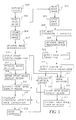
- Fig. 5 is a flow diagram showing the image processing steps for automatic formation of a full composite image from first and second images.
- Fig. 6 shows the major image processing steps that are used to automatically find the locations and orientations of the screen ending edges in both the front and the back images, and for finding the location and orientation of the shadow of the front screen ending edge in the back image.
- Fig. 7 shows the major image processing steps that are used for finding the horizontal displacement between the front and back images by image-correlation.
- Fig. 8 shows the composite, stitched full image.
- the present invention relates to the radiographic imaging of an elongate object such as the full spine (for diagnosing scoliosis, for example) or leg of a human subject.
- Two contiguous CR plates contained in an elongated cassette are exposed to a radiographic image of an elongate object to produce a latent image stored in the CR plates.
- the CR plates are removably mounted in the cassette and are sequentially fed to a CR reader where the latent radiographic images are converted to two electronic images which are combined to form an elongated image.
- the elongate image can be displayed on an electronic display or printed out on hard copy media.
- storage phosphor cassette 10 includes an elongate rectangular shell 12 having first and second open ends 14 and 16.
- a first storage phosphor plate assembly 18 is detachably mounted in shell 12 from the first open end 14.
- a second storage phosphor plate assembly 20 is detachably mounted on shell 12 from the second open end 16.
- Each assembly 18, 20 includes a respective storage phosphor plate 22, 24 and a support and latching assembly 26, 28. Plates 22, 24 are butt joined or overlapped in the central region 29 of shell 12.
- Shell 12 includes upper and lower members 30, 32 and side extrusions 34, 36 which together form a rectangular shell.
- Fig. 2 shows first storage phosphor assembly 18 partially detached from cassette 10 at a reading device (not shown).
- Fig. 3 shows a cross-section of cassette 10 showing upper and lower members 30, 32 having respective opposed inner surfaces 40, 42 including deflectors 44, 46 extending therefrom for guiding the inner ends of assemblies 18, 20 to overlap.
- the first and second images read from first and second storage phosphor plates 22 and 24 are formed into a composite image according to the method of the present invention as follows.
- the generation of a full composite image from the front and back images is comprised of the following steps: (1) demagnification of each image pixel based on the distance between the x-ray source and the physical location of the pixel in the individual phosphor screen, (2) determination of the rotational displacement and the vertical displacement between the front and back images by matching the front screen ending edge in the front image to it's shadow in the back image, (3) image orientation correction based on the rotational displacement, (4) determination of the horizontal displacement between the front and back images by correlating the image information in the overlapping screen regions, and (5) stitching the front and the back images together along the front screen ending edge based on the horizontal and vertical displacements.
- the patient 403 is positioned in the path of the x-ray beam 402 from the x-ray tube 401.
- the extended length cassette 405 is placed behind the patient in order to record the image of the patient.
- the extended length cassette 405 can be used with an anti-scatter grid 404, which is positioned behind the patient 403 but directly in front of the cassette.
- the grid can be either a stationary type or moving bucky.
- the back screen 407 can still record the image of the patient 403 in the screen overlap region 427.
- the signal-to-noise ratio of the image captured on the back screen in the overlap region 427 will be relatively low because of the x-ray attenuation caused by the front screen .
- the image content recorded by the two screens in the overlap region is the same. This redundant information is then used to register the front and back images to produce a full patient image.
- the front screen ending edge 408 can impose a distinctive edge shadow on the back screen. By comparing the location and orientation of the front screen ending edge with its shadow in the back image, the relative orientation and vertical displacement between the two images is determined.
- the exposure process described in this paragraph corresponds to element 500 in Fig.5.
- the extended length CR cassette is sent to the CR reader for image readout.
- the front phosphor screen 410 is scanned using a laser beam in a line-by-line format as described by element 412.
- the depicted signal from the phosphor screen which is linearly proportional to the magnitude of the recorded patient image signal, is extracted and converted into digital format.
- the CR reader may stop the reading process when the laser scan line nearly reaches the screen ending edge 414. This does not guarantee that the complete information of the ending edge will be recorded in the acquired image, which is required by this invention for image registration. To address this issue, the CR reader must over-scan the phosphor screen, i.e., scan slightly beyond the end of the screen. In Fig.
- element 420 represents the image acquired from the front screen, and shows that the screen ending edge, 422, is captured completely inside the image.
- the front image therefore is partitioned into two regions by the screen ending edge: the normal image area and the over-scanned image area.
- the cassette is removed from the reader and inverted to allow the back screen 407 (411) to be read in the same manner as the front screen.
- the laser beam conducts the scan in a format as indicated by element 413. Therefore, to restore the correct orientation of the back image, the acquired image must be flipped once horizontally and once vertically after being stored in the CR memory.
- Element 421 shows the acquired back image after the flip operations.
- the back screen Since both the back and front screens are of the same size, the back screen will also be over-scanned beyond its ending edge 415 (Fig. 4B). Consequently, the screen ending edge 423 will be captured completely inside the acquired back image 421. Due to screen overlap, the front screen ending edge 414 is also recorded by the back screen, which is indicated by element 425. The back image is therefore partitioned into three regions by the shadow of the front screen ending edge and further by the back screen ending edge.
- the end-to-end readout and storage process described in this paragraph corresponds to element 502, 504, 503, 505, and 506 as shown in Fig. 5.
- the front and back storage phosphor screens are not exactly co-planar inside the extended cassette, there is a location dependent, although slight, geometric distortion (magnification) that is introduced, as indicated by elements 416 and 417.
- the mismatch between the front and back images in the overlap region can be as large as 0.5 mm in the image horizontal axis. This can significantly impact the stitching precision and introduce discontinuity adjacent to the seam line in the stitched image. It is therefore necessary to perform distortion correction, especially as the distortion conspicuity increases as the SID decreases.
- the distortion correction process is accomplished using a mathematical model that is based on the geometric placement of the phosphor screens inside the cassette.
- the design of the extended length cassette forces the top of the front screen and the bottom of the back screen to be coplanar such that there is no geometric distortion near the two ends of the cassette. As the distance from either cassette end to the center decreases, the magnification increases. This phenomenon is more dominant in the horizontal axis than that in the vertical axis.
- Eq. 1 essentially conducts variable correction for each image row but ignores the very small distortion in the vertical direction. The correction is conducted symmetric to the middle column of the image, which is valid because during the x-ray exposure the central x-ray beam is normally centered with the cassette.
- This image demagnification process is indicated by elements 507 and 508 in Fig. 5. This processing step can be ignored when the SID becomes large (>> 180 cm), as the distortion introduced by the magnification factor is negligible.
- the screen ending edges in both the front and the back images must be located. This operation is shown by elements 509 and 510 in Fig. 5.
- the pixel values in the image region that is beyond the screen ending edge reflect the baseline noise level of the CR reader. This is because there is no signal contribution from the phosphor screen. Consequently, the pixel values in these regions are relatively low in comparison to those in the normally exposed image regions, therefore there is an abrupt pixel value decrement/discontinuity across the screen ending edge in the image.
- This pixel value discontinuity is used to detect the location and orientation of the screen ending edges, which can be accomplished in many ways. In the preferred embodiment of the present invention, the detection is carried out by (1) computing all the significant edge transition pixels in the proximity of the screen ending edge location, and (2) performing line delineation of the screen ending edge pixels.
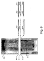
- Fig. 6 describes the preferred embodiment of the detection process.
- a narrow band 602 is extracted from the end of the front image 600.
- the orientation of the screen ending edge 601 can have a variation of several degrees in the acquired image from one scan to the next scan. Therefore, the size of the narrow band must be large enough such that the entire screen ending edge is reliably extracted.
- the size of the narrow band should be approximately 200 x 2,048 pixels.
- the one-dimensional derivative of the image which is computed in the vertical direction using an operator [-1, 0, 1].
- a one-dimensional derivative operator is preferred because the pixel value discontinuity only occurs across the edge direction, which is always nearly horizontal, and because of the computational efficiency advantages.
- a predefined threshold is used to select only those candidate edge transition pixels which are of greater magnitude and of falling slope. Element 603 shows the results from this step.
- a linear function is fitted to the candidate edge pixels and the best fitting parameters are obtained when the least square error is reached.
- Element 604 shows the fitted linear function overlaid on top of the edge transition pixels.
- this process is conducted for the back image 610, except rising edge transition pixels are searched instead inside a narrow band 614 at the beginning of the processed back image.
- the screen ending edge location is successfully found in the front image, it is compared with its shadow in the back image for image registration.
- a similar approach to element 509 is used. This is possible because the pixel values in the back image also undergo a strong signal intensity decrement in the screen overlap region 427 (Fig. 4C) due to the high attenuation of the incident x-rays by the front screen during the x-ray exposure.
- the location of the narrow band needs to be defined in the back image.
- parameters k f and k should be equal because they both represent the orientation of the front screen ending edge. However, they may differ by as much as several degrees in practice for several reasons such as misalignment between the two phosphor screens in the cassette or screen positioning variations in the CR reader during the readout process.
- the deviation between k f and k represents the orientation misalignment between the front and back images. To assure a seamless composite image after stitching, and to preserve high geometric fidelity, this misalignment must be corrected.
- the first and the second methods have the advantage of reduced computation because only one of the two images must be rotated.
- the orientation of the resultant front screen ending edge which is also the orientation of the seam line in the composite stitched image, may still contain some residual mis-registration in the horizontal direction which can cause the seam line in the stitched image to appear jagged.
- the third method overcomes this disadvantage.
- Fig. 5, element 513 shows the effect of rotating the back image.
- Element 512, which shows the effect of rotating the front image is optional depending on whether method 2 or method 3 was used Since the parameters that are used for aligning the front and back images, e.g., k a , k b , k, a a , a b , and a , are calculated before image rotation, the parameters must be transformed accordingly to reflect the new values in the rotated image(s).
- the location of the screen overlap region 427 (Fig. 4C) in the back image can be defined.
- the screen overlap region in the back image is located between the back screen ending edge and the shadow of the front screen ending edge.
- Element 515 shows the aforementioned process.
- the image content recorded in the overlap regions are the same except for some horizontal displacement, y_offset , between the corresponding pixels.
- the ⁇ value at which c ( ⁇ ) reaches a maximum is the optimal value for y_offset.
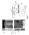
- Fig. 7 describes the preferred implementation of this operation.
- the overlap region 702 and 703 are extracted from the front and back images respectively.
- element 704 is obtained by extracting a portion of 702, then is correlated with 703 to create the correlation function c( ⁇ ) , 706. Similar results can be achieved by correlating a portion of 703 with 702.
- the maximum of function c( ⁇ ) is searched and the corresponding value of ⁇ is identified as y_offset , 707. Because the edge information in 702 and 703, including skin line, tissue boundaries, bone edges, collimation boundaries, and hardware labels etc, contribute the most useful information to the correlation, the low frequency content is removed from 702 and 703 in order to improve the correlation robustness.
- the correlation function is smooth, as indicated by element 810 (Fig. 8).
- element 810 Fig. 8
- small periodic peaks can appear in the function, as indicated by element 811 (Fig. 8).
- the stationary grid imposes a periodic line pattern artifact in the acquired images, the artifact is particularly dominant when the grid is orientated in the vertical direction, and can correlate with itself, causing small spikes to be introduced on top of the back ground correlation function. This artifact will negatively impact the accuracy of the determination of the location of the true function maximum.
- low-pass filtering of the correlation function is used before searching for the maximum.
- the process described in this paragraph is represented by element 531 (fig. 5).
- the back image is stitched to the front image.
- Each pixel of the front image is copied to the stitched image buffer except those pixels that are beyond the screen ending edge line.
- Each pixel in the back image is copied to the stitched image buffer with an displacement defined by x_offset and y_offset except those pixels before the shadow of the front screen ending edge.
- the resultant image is shown in Fig. 9.
- the process conducted in this paragraph is represented by element 532 (Fig. 5).
Landscapes
- Physics & Mathematics (AREA)
- General Physics & Mathematics (AREA)
- Health & Medical Sciences (AREA)
- Life Sciences & Earth Sciences (AREA)
- High Energy & Nuclear Physics (AREA)
- Molecular Biology (AREA)
- Spectroscopy & Molecular Physics (AREA)
- Image Processing (AREA)
- Apparatus For Radiation Diagnosis (AREA)
- Image Analysis (AREA)
- Editing Of Facsimile Originals (AREA)
Applications Claiming Priority (2)
| Application Number | Priority Date | Filing Date | Title |
|---|---|---|---|
| US782724 | 1985-10-01 | ||
| US09/782,724 US6459094B1 (en) | 2000-12-20 | 2001-02-13 | Method for stitching partial radiation images to reconstruct a full image |
Publications (3)
| Publication Number | Publication Date |
|---|---|
| EP1231484A2 true EP1231484A2 (de) | 2002-08-14 |
| EP1231484A3 EP1231484A3 (de) | 2006-08-09 |
| EP1231484B1 EP1231484B1 (de) | 2012-12-26 |
Family
ID=25126976
Family Applications (1)
| Application Number | Title | Priority Date | Filing Date |
|---|---|---|---|
| EP02075399A Expired - Lifetime EP1231484B1 (de) | 2001-02-13 | 2002-02-01 | Verfahren zum Wiederaufbau des Strahlungsbildes aus Strahlungsteilbildern |
Country Status (3)
| Country | Link |
|---|---|
| US (1) | US6459094B1 (de) |
| EP (1) | EP1231484B1 (de) |
| JP (1) | JP2002301055A (de) |
Cited By (4)
| Publication number | Priority date | Publication date | Assignee | Title |
|---|---|---|---|---|
| EP1408450A2 (de) | 2002-10-10 | 2004-04-14 | Eastman Kodak Company | Automatische Ermittlung der Anordnung von partiellen Strahlungsbildern zur Rekonstruktion eines gehefteten Vollbildes |
| EP1291677A3 (de) * | 2001-09-11 | 2007-08-22 | Eastman Kodak Company | Verfahren zum Zusammenflicken von Strahlungs-Teilbildern zwecks Erzeugung eines ganzen Bildes |
| US7801351B2 (en) | 2005-11-22 | 2010-09-21 | General Electric Company | Method and system to manage digital medical images |
| US11213261B2 (en) * | 2017-10-06 | 2022-01-04 | Canon Kabushiki Kaisha | Radiographic system and radiographic method |
Families Citing this family (40)
| Publication number | Priority date | Publication date | Assignee | Title |
|---|---|---|---|---|
| US7791626B2 (en) * | 2001-05-30 | 2010-09-07 | Zink Imaging, Inc. | Print head pulsing techniques for multicolor printers |
| US8377844B2 (en) * | 2001-05-30 | 2013-02-19 | Zink Imaging, Inc. | Thermally-insulating layers and direct thermal imaging members containing same |
| US7830405B2 (en) * | 2005-06-23 | 2010-11-09 | Zink Imaging, Inc. | Print head pulsing techniques for multicolor printers |
| US7388686B2 (en) * | 2003-02-25 | 2008-06-17 | Zink Imaging, Llc | Image stitching for a multi-head printer |
| DE10134651A1 (de) * | 2001-07-20 | 2003-02-06 | Siemens Ag | Verfahren und Vorrichtung zur Erstellung eines Gesamtbildes aus mehreren Teilbildern |
| US7010152B2 (en) * | 2002-01-22 | 2006-03-07 | Canon Kabushiki Kaisha | Radiographic image composition and use |
| JP4230731B2 (ja) * | 2002-07-29 | 2009-02-25 | 株式会社東芝 | ディジタル画像処理装置及びx線診断装置 |
| US6944265B2 (en) * | 2002-11-25 | 2005-09-13 | Ge Medical Systems Global Technology Company, Llc | Image pasting using geometry measurement and a flat-panel detector |
| US20040143153A1 (en) * | 2003-01-17 | 2004-07-22 | Sharrow James S. | Devices and methods for manipulation of organ tissue |
| JP4393135B2 (ja) * | 2003-08-22 | 2010-01-06 | キヤノン株式会社 | 放射線画像処理装置、放射線画像処理方法、コンピュータプログラム、及びコンピュータ読み取り可能な記録媒体 |
| US7416267B2 (en) | 2004-03-23 | 2008-08-26 | Zink Imaging, Llc | Print job data processing for multi-head printers |
| ATE373285T1 (de) * | 2004-05-04 | 2007-09-15 | Agfa Gevaert Healthcare Gmbh | Verfahren zur erfassung und darstellung eines in einer phosphorschicht gespeicherten röntgenbildes |
| US7734325B2 (en) * | 2004-09-21 | 2010-06-08 | Carestream Health, Inc. | Apparatus and method for multi-modal imaging |
| US7304321B2 (en) * | 2004-10-15 | 2007-12-04 | Orex Computed Radiography, Ltd. | Methods and apparatus for imaging elongate objects |
| US7671342B2 (en) * | 2005-01-11 | 2010-03-02 | Siemens Medical Solutions Usa, Inc. | Multi-layer detector and method for imaging |
| US20060262902A1 (en) * | 2005-05-19 | 2006-11-23 | The Regents Of The University Of California | Security X-ray screening system |
| JP2009503544A (ja) * | 2005-08-01 | 2009-01-29 | バイオプティジェン,インコーポレイテッド | 試料から取得された3次元データセットを解析する方法、システム及びコンピュータ・プログラムプロダクト |
| US8660631B2 (en) * | 2005-09-08 | 2014-02-25 | Bruker Biospin Corporation | Torsional support apparatus and method for craniocaudal rotation of animals |
| US20090281383A1 (en) * | 2005-09-08 | 2009-11-12 | Rao Papineni | Apparatus and method for external fluorescence imaging of internal regions of interest in a small animal using an endoscope for internal illumination |
| US8041409B2 (en) * | 2005-09-08 | 2011-10-18 | Carestream Health, Inc. | Method and apparatus for multi-modal imaging |
| US20100220836A1 (en) * | 2005-09-08 | 2010-09-02 | Feke Gilbert D | Apparatus and method for multi-modal imaging |
| US8203132B2 (en) * | 2005-09-08 | 2012-06-19 | Carestream Health, Inc. | Apparatus and method for imaging ionizing radiation |
| US8050735B2 (en) * | 2005-09-08 | 2011-11-01 | Carestream Health, Inc. | Apparatus and method for multi-modal imaging |
| DE102006021051A1 (de) * | 2006-05-05 | 2007-11-15 | Siemens Ag | Verfahren zur Generierung eines medizinischen Bildes und medizinisches Bildaufnahmesystem |
| EP2092483A4 (de) * | 2006-09-19 | 2010-12-22 | Cedara Software Corp | System und verfahren zur blendendetektion |
| WO2009022408A1 (ja) * | 2007-08-13 | 2009-02-19 | Shimadzu Corporation | 放射線撮像装置 |
| CN101910869B (zh) * | 2008-01-18 | 2016-01-13 | 皇家飞利浦电子股份有限公司 | 多段重建 |
| DE102009047867B4 (de) * | 2009-09-30 | 2016-10-06 | Siemens Healthcare Gmbh | Verfahren und Vorrichtung zur Korrektur von trunkierten Projektionsdaten |
| US8744159B2 (en) * | 2010-03-05 | 2014-06-03 | Bioptigen, Inc. | Methods, systems and computer program products for collapsing volume data to lower dimensional representations thereof using histogram projection |
| WO2011156948A1 (en) * | 2010-06-13 | 2011-12-22 | Nanjing University | Reconstruction of overlapped objects in image |
| KR101887188B1 (ko) | 2011-11-21 | 2018-08-10 | 삼성전자주식회사 | 복수의 영상들을 접합하기 위한 방법 및 장치 |
| US20140264078A1 (en) * | 2013-03-12 | 2014-09-18 | Agfa Healthcare Nv | Radiation Image Read-Out and Cropping System |
| US9377291B2 (en) | 2013-12-05 | 2016-06-28 | Bioptigen, Inc. | Image registration, averaging, and compounding for high speed extended depth optical coherence tomography |
| JP6099620B2 (ja) * | 2014-03-03 | 2017-03-22 | 富士フイルム株式会社 | 放射線画像撮影装置 |
| JP6169626B2 (ja) * | 2014-03-10 | 2017-07-26 | 富士フイルム株式会社 | 放射線画像処理装置、方法およびプログラム |
| JP6072096B2 (ja) * | 2015-01-30 | 2017-02-01 | キヤノン株式会社 | 放射線撮影システム、制御方法、制御方法、及びプログラム |
| JP6412815B2 (ja) * | 2015-02-26 | 2018-10-24 | 富士フイルム株式会社 | 放射線画像撮影システム、撮影台、及び撮影方法 |
| JP6363573B2 (ja) * | 2015-09-24 | 2018-07-25 | 富士フイルム株式会社 | 線源画像面間距離取得装置、方法およびプログラム、並びに放射線画像処理装置、方法およびプログラム |
| DE102018114460B3 (de) * | 2018-06-15 | 2019-06-06 | Dürr Dental SE | Röntgenspeicherfoliensystem |
| US11253212B2 (en) * | 2020-01-07 | 2022-02-22 | General Electric Company | Tileable X-ray detector cassettes |
Citations (7)
| Publication number | Priority date | Publication date | Assignee | Title |
|---|---|---|---|---|
| US5712890A (en) | 1994-11-23 | 1998-01-27 | Thermotrex Corp. | Full breast digital mammography device |
| EP0866342A1 (de) | 1997-03-21 | 1998-09-23 | Agfa-Gevaert N.V. | Verfahren zur Aufzeichnung und Wiedergabe eines Strahlungsbildes von einem länglichen Körper |
| EP0919856A1 (de) | 1997-12-01 | 1999-06-02 | Agfa-Gevaert N.V. | Verfahren und Vorrichtung zur Aufzeichnung eines Strahlungsbildes von einem länglichen Körper |
| EP0919858A1 (de) | 1997-12-01 | 1999-06-02 | Agfa-Gevaert N.V. | Verfahren zum Wiederaufbau des Strahlungsbildes eines Körpers aus Strahlungsteilbildern |
| US5986279A (en) | 1997-03-21 | 1999-11-16 | Agfa-Gevaert | Method of recording and reading a radiation image of an elongate body |
| JP2000275760A (ja) | 1999-03-23 | 2000-10-06 | Fuji Photo Film Co Ltd | 放射線画像の連結処理方法および放射線画像処理装置 |
| US6600831B1 (en) | 1999-03-23 | 2003-07-29 | Fuji Photo Film Co., Ltd. | Connection processing method for radiation images |
Family Cites Families (4)
| Publication number | Priority date | Publication date | Assignee | Title |
|---|---|---|---|---|
| JPH09320931A (ja) * | 1996-05-28 | 1997-12-12 | Nikon Corp | 結像特性計測方法及び該方法を使用する転写装置 |
| JP2970581B2 (ja) | 1997-03-18 | 1999-11-02 | 日本電気株式会社 | Lanエミュレーションにおける同報パケット転送方法及びそのlsi装置 |
| US6180947B1 (en) * | 1998-08-07 | 2001-01-30 | Nikon Corporation | Multi-element deflection aberration correction for electron beam lithography |
| JP4132373B2 (ja) * | 1999-03-23 | 2008-08-13 | 富士フイルム株式会社 | 放射線画像の連結処理方法および放射線画像処理装置 |
-
2001
- 2001-02-13 US US09/782,724 patent/US6459094B1/en not_active Expired - Lifetime
-
2002
- 2002-02-01 EP EP02075399A patent/EP1231484B1/de not_active Expired - Lifetime
- 2002-02-08 JP JP2002032905A patent/JP2002301055A/ja active Pending
Patent Citations (7)
| Publication number | Priority date | Publication date | Assignee | Title |
|---|---|---|---|---|
| US5712890A (en) | 1994-11-23 | 1998-01-27 | Thermotrex Corp. | Full breast digital mammography device |
| EP0866342A1 (de) | 1997-03-21 | 1998-09-23 | Agfa-Gevaert N.V. | Verfahren zur Aufzeichnung und Wiedergabe eines Strahlungsbildes von einem länglichen Körper |
| US5986279A (en) | 1997-03-21 | 1999-11-16 | Agfa-Gevaert | Method of recording and reading a radiation image of an elongate body |
| EP0919856A1 (de) | 1997-12-01 | 1999-06-02 | Agfa-Gevaert N.V. | Verfahren und Vorrichtung zur Aufzeichnung eines Strahlungsbildes von einem länglichen Körper |
| EP0919858A1 (de) | 1997-12-01 | 1999-06-02 | Agfa-Gevaert N.V. | Verfahren zum Wiederaufbau des Strahlungsbildes eines Körpers aus Strahlungsteilbildern |
| JP2000275760A (ja) | 1999-03-23 | 2000-10-06 | Fuji Photo Film Co Ltd | 放射線画像の連結処理方法および放射線画像処理装置 |
| US6600831B1 (en) | 1999-03-23 | 2003-07-29 | Fuji Photo Film Co., Ltd. | Connection processing method for radiation images |
Cited By (6)
| Publication number | Priority date | Publication date | Assignee | Title |
|---|---|---|---|---|
| EP1291677A3 (de) * | 2001-09-11 | 2007-08-22 | Eastman Kodak Company | Verfahren zum Zusammenflicken von Strahlungs-Teilbildern zwecks Erzeugung eines ganzen Bildes |
| EP1408450A2 (de) | 2002-10-10 | 2004-04-14 | Eastman Kodak Company | Automatische Ermittlung der Anordnung von partiellen Strahlungsbildern zur Rekonstruktion eines gehefteten Vollbildes |
| US6793390B2 (en) * | 2002-10-10 | 2004-09-21 | Eastman Kodak Company | Method for automatic arrangement determination of partial radiation images for reconstructing a stitched full image |
| EP1408450A3 (de) * | 2002-10-10 | 2009-07-01 | Carestream Health, Inc. | Automatische Ermittlung der Anordnung von partiellen Strahlungsbildern zur Rekonstruktion eines gehefteten Vollbildes |
| US7801351B2 (en) | 2005-11-22 | 2010-09-21 | General Electric Company | Method and system to manage digital medical images |
| US11213261B2 (en) * | 2017-10-06 | 2022-01-04 | Canon Kabushiki Kaisha | Radiographic system and radiographic method |
Also Published As
| Publication number | Publication date |
|---|---|
| US6459094B1 (en) | 2002-10-01 |
| US20020109113A1 (en) | 2002-08-15 |
| EP1231484B1 (de) | 2012-12-26 |
| JP2002301055A (ja) | 2002-10-15 |
| EP1231484A3 (de) | 2006-08-09 |
Similar Documents
| Publication | Publication Date | Title |
|---|---|---|
| US6459094B1 (en) | Method for stitching partial radiation images to reconstruct a full image | |
| US6895106B2 (en) | Method for stitching partial radiation images to reconstruct a full image | |
| US6269177B1 (en) | Method for reconstructing radiation image of a body from partial radiation images | |
| US6273606B1 (en) | Method and assembly for recording a radiation image of an elongate body | |
| US6793390B2 (en) | Method for automatic arrangement determination of partial radiation images for reconstructing a stitched full image | |
| CN111803110B (zh) | X射线透视摄影装置 | |
| EP1417931A1 (de) | Verfahren zum automatischen Erzeugen von eines Röntgenbild in Original Grösse | |
| US7265355B2 (en) | Method and system for acquiring full spine and full leg images using flat panel digital radiography | |
| US20020018586A1 (en) | Method of and system for detecting prospective abnormal shadow and method of reproducing radiation image | |
| EP0919858B1 (de) | Verfahren zum Zusammensetzen des Strahlungsbildes eines Körpers aus Strahlungsteilbildern | |
| US7912263B2 (en) | Method for detecting clipped anatomy in medical images | |
| US9004757B2 (en) | Systems, assemblies, computer readable media and methods for medical imaging | |
| JP2000339444A (ja) | 放射線画像の連結処理方法および放射線画像処理装置 | |
| JP2001202507A (ja) | 画像の位置合わせ処理方法および位置合わせ処理装置 | |
| US7479648B2 (en) | Methods and apparatus for imaging elongate objects | |
| JP4132373B2 (ja) | 放射線画像の連結処理方法および放射線画像処理装置 | |
| JP4083337B2 (ja) | 放射線画像の連結処理方法および放射線画像処理装置 | |
| JP3800892B2 (ja) | 放射線画像処理装置 | |
| US20020121612A1 (en) | Elongated computed radiography cassette having image alignment aid | |
| US7329890B2 (en) | Computed radiography cassette system | |
| JP2000157519A (ja) | 画像処理装置 | |
| Dewaele et al. | Full-leg/full-spine image stitching: a new and accurate CR-based imaging technique | |
| US7386091B2 (en) | X-ray mammography machine having a digital flat solid state detector | |
| JP2001307085A (ja) | 画像の連結処理方法および画像処理装置 | |
| JP2001008099A (ja) | 経時サブトラクション方法および装置並びに記録媒体 |
Legal Events
| Date | Code | Title | Description |
|---|---|---|---|
| PUAI | Public reference made under article 153(3) epc to a published international application that has entered the european phase |
Free format text: ORIGINAL CODE: 0009012 |
|
| AK | Designated contracting states |
Kind code of ref document: A2 Designated state(s): AT BE CH CY DE DK ES FI FR GB GR IE IT LI LU MC NL PT SE TR |
|
| AX | Request for extension of the european patent |
Free format text: AL;LT;LV;MK;RO;SI |
|
| PUAL | Search report despatched |
Free format text: ORIGINAL CODE: 0009013 |
|
| AK | Designated contracting states |
Kind code of ref document: A3 Designated state(s): AT BE CH CY DE DK ES FI FR GB GR IE IT LI LU MC NL PT SE TR |
|
| AX | Request for extension of the european patent |
Extension state: AL LT LV MK RO SI |
|
| 17P | Request for examination filed |
Effective date: 20061222 |
|
| 17Q | First examination report despatched |
Effective date: 20070228 |
|
| AKX | Designation fees paid |
Designated state(s): DE FR GB |
|
| RAP1 | Party data changed (applicant data changed or rights of an application transferred) |
Owner name: CARESTREAM HEALTH, INC. |
|
| GRAP | Despatch of communication of intention to grant a patent |
Free format text: ORIGINAL CODE: EPIDOSNIGR1 |
|
| GRAS | Grant fee paid |
Free format text: ORIGINAL CODE: EPIDOSNIGR3 |
|
| GRAA | (expected) grant |
Free format text: ORIGINAL CODE: 0009210 |
|
| AK | Designated contracting states |
Kind code of ref document: B1 Designated state(s): DE FR GB |
|
| REG | Reference to a national code |
Ref country code: GB Ref legal event code: FG4D |
|
| REG | Reference to a national code |
Ref country code: DE Ref legal event code: R096 Ref document number: 60244271 Country of ref document: DE Effective date: 20130228 |
|
| PLBE | No opposition filed within time limit |
Free format text: ORIGINAL CODE: 0009261 |
|
| STAA | Information on the status of an ep patent application or granted ep patent |
Free format text: STATUS: NO OPPOSITION FILED WITHIN TIME LIMIT |
|
| 26N | No opposition filed |
Effective date: 20130927 |
|
| REG | Reference to a national code |
Ref country code: DE Ref legal event code: R097 Ref document number: 60244271 Country of ref document: DE Effective date: 20130927 |
|
| REG | Reference to a national code |
Ref country code: FR Ref legal event code: PLFP Year of fee payment: 15 |
|
| REG | Reference to a national code |
Ref country code: FR Ref legal event code: PLFP Year of fee payment: 16 |
|
| REG | Reference to a national code |
Ref country code: FR Ref legal event code: PLFP Year of fee payment: 17 |
|
| PGFP | Annual fee paid to national office [announced via postgrant information from national office to epo] |
Ref country code: DE Payment date: 20200115 Year of fee payment: 19 Ref country code: GB Payment date: 20200130 Year of fee payment: 19 |
|
| PGFP | Annual fee paid to national office [announced via postgrant information from national office to epo] |
Ref country code: FR Payment date: 20200124 Year of fee payment: 19 |
|
| REG | Reference to a national code |
Ref country code: DE Ref legal event code: R119 Ref document number: 60244271 Country of ref document: DE |
|
| GBPC | Gb: european patent ceased through non-payment of renewal fee |
Effective date: 20210201 |
|
| PG25 | Lapsed in a contracting state [announced via postgrant information from national office to epo] |
Ref country code: FR Free format text: LAPSE BECAUSE OF NON-PAYMENT OF DUE FEES Effective date: 20210228 Ref country code: GB Free format text: LAPSE BECAUSE OF NON-PAYMENT OF DUE FEES Effective date: 20210201 Ref country code: DE Free format text: LAPSE BECAUSE OF NON-PAYMENT OF DUE FEES Effective date: 20210901 |