EP1231104A1 - Fussschaltereinheit für Ladeplattformen von Ladebordwandsystemen - Google Patents
Fussschaltereinheit für Ladeplattformen von Ladebordwandsystemen Download PDFInfo
- Publication number
- EP1231104A1 EP1231104A1 EP01102677A EP01102677A EP1231104A1 EP 1231104 A1 EP1231104 A1 EP 1231104A1 EP 01102677 A EP01102677 A EP 01102677A EP 01102677 A EP01102677 A EP 01102677A EP 1231104 A1 EP1231104 A1 EP 1231104A1
- Authority
- EP
- European Patent Office
- Prior art keywords
- plate
- switch unit
- foot switch
- shaped element
- unit according
- Prior art date
- Legal status (The legal status is an assumption and is not a legal conclusion. Google has not performed a legal analysis and makes no representation as to the accuracy of the status listed.)
- Withdrawn
Links
Images

Classifications
-
- B—PERFORMING OPERATIONS; TRANSPORTING
- B60—VEHICLES IN GENERAL
- B60P—VEHICLES ADAPTED FOR LOAD TRANSPORTATION OR TO TRANSPORT, TO CARRY, OR TO COMPRISE SPECIAL LOADS OR OBJECTS
- B60P1/00—Vehicles predominantly for transporting loads and modified to facilitate loading, consolidating the load, or unloading
- B60P1/44—Vehicles predominantly for transporting loads and modified to facilitate loading, consolidating the load, or unloading having a loading platform thereon raising the load to the level of the load-transporting element
- B60P1/4471—General means for controlling movements of the loading platform, e.g. hydraulic systems
Definitions
- the invention relates to a foot switch unit for Loading platforms of tail lift systems for vehicles, with which the loading platform by appropriate actuation caused by foot switches to raise and lower is comprising a housing in which the foot switch are present, with the housing on the loading platform is attachable.
- Foot switch units of this type come in a wide variety Variants used with loading platforms.
- Tail lift systems are regularly subject to a rough Handling by the operator operating the loading platform can be raised and lowered, especially if the operator with the load on the loading platform standing raising and lowering with your feet initiated via the foot switch.
- the previously known foot switch units are also designed such that they are on the operator side opposite side electronic and / or electrical Have control and / or regulating devices, which serve the purpose of that of the actual foot switches for lifting and lowering the tail lift prepare given electrical signals and to a control unit for the tail lift system in to convey its entirety.
- the foot switch units relatively massive, i.e. in your Thickness, based on the loading platform, very high and, also related to the loading platform, very wide to create a space on the back in which the electrical and / or electronic control and Control device can be accommodated, wherein this space to be created on the bottom or back the foot switch unit for the aforementioned purposes too still water-, dust-vapor-tight and the like.
- Encapsulated must be what additional space for the hermetic Encapsulation required.
- the above-mentioned high and massive education of the Housing of the foot switch device also has one Another significant disadvantage, especially if the foot switch unit in the case of so-called folding platforms trained loading platforms should be used and even if the loading platforms are in the form of so-called Refrigerated cases trained vehicle bodies used should be.
- the so-called folding loading platforms With the so-called folding loading platforms, the Loading platform folded during non-operation and in folded state under the rear of the cargo area of the vehicle moved.
- One in the clear height too large foot switch unit, as is known up to now, is for the support and the support of the loading platform elements extremely cumbersome when folded and measures must be taken to ensure that the Foot switch unit itself not directly on the part of the loading platform folded on it comes.
- the housing consists of a plate-shaped element.
- a housing plate-shaped element according to the invention both for Folding loading platforms as well as in connection with loading platforms, those with refrigerated cases as vehicle bodies are equipped to use as for both applications the thickness of the plate-like element so can be kept low that the door of the refrigerator even with the loading platform raised in the end position without Difficulty can be opened and closed and no impairment when used with folding loading platforms the folding options.
- the Solution according to the invention can be implemented very inexpensively and the solution according to the invention is simple on the Attachable loading platform.
- the plate-shaped element has a substantially U-shaped cross section, which increases stability of the plate-shaped element can be increased at simultaneous possibility of reducing the distance the levels of the plate, i.e. a decrease the thick.
- the webs point in relation to the inner surface or inner plane of the element if there is a U-shaped profile Cross section has a height corresponding to Height of webs protruding from the loading platform.
- a variety of loading platforms have a profiled Surface cross-section, i.e. from the surface There are webs on the loading platform, i.e. away from the loading platform.
- the averted when the loading platform is fastened is at least partially covering the element second element arranged.
- This second plate-shaped Element where the distance between the two is essentially parallel planes also small compared to the other dimensions, i.e. the thickness of the plate is small, has the task of a certain separation between e.g. from at both ends of the first plate-shaped element arranged foot switches to effect.
- the second plate-shaped element also causes Goods placed on the foot switch unit in error cannot trigger the foot switch, because the second plate-shaped element sets for it Obstacle.
- the second plate-shaped element can preferably also be used the first plate-shaped element integrally formed be, i.e. be made from one piece, but it is also preferably possible, the second plate-shaped Element on the first plate-shaped element attach, i.e. to train beforehand as a separate part, and then, for example, by means of screw connections on the to attach the first plate-shaped element.
- the second plate-shaped element can, similar to that first plate-shaped element, acc. another advantageous embodiment of the foot switch unit in Cross-section essentially U-shaped be, one between the webs thus formed flat opening corresponding to the inner opening between the webs of the first plate-shaped element becomes.
- This measure can also be used for reduction the thickness of the second plate-shaped element Stability can be achieved, i.e. also i.V.m. the correspondingly U-shaped first plate-shaped element.
- marking and / or information means can be provided the operator of the foot switch unit Notes on the foot switches to be operated via the Giving and lowering the loading platform and if necessary also Warning notices regarding possible incorrect actuation options.
- foot switch of the foot switch unit very much be flat so that they are essentially as possible not thicker or higher than the first plate-shaped Element are.
- foot-operated switch preferably microswitch or preferably sensor switches compared in the trade for their lateral expansion with small thicknesses are available and also encapsulate slightly waterproof leave or already in waterproof and dustproof configuration Tobe offered.
- the foot-operated ones are advantageous Interacting electrical and / or switches electronic control and / or regulating devices arranged away from the foot switch unit, i.e. it need according to the invention in the loading platform on site no openings for fastening the foot switch unit be provided in which, as in some cases so far, space had to be provided to the previously shown funds to be able to accommodate.
- the preferred one Design of the foot switch unit also has the Advantage that the foot switch unit only with respect of the foot-operated switch with corresponding advanced electrical lines are connected have to.
- the regulation and / or control of lifting, Lowering and possibly folding or collapsing the Loading platform takes place centrally from a corresponding one Control unit on the vehicle for the operator accessible place is arranged.
- the solution of the invention downright offers the plate-shaped element in strip-shaped To have lengths produced as semi-finished products and this preferably only in the desired dimension cut to length, i.e. in a simple way to the desired one Length corresponding to the overall dimension of the tail lift system adapt and thus in a simple way different designs of the tail lift system to be able to adapt.
- the plate-shaped element has any suitable mechanical and resistant to environmental influences It is advantageous to use material, at least the plate-shaped element made of a light metal material produce the one hand high strength and on the other hand, a low weight and also suitable Alloy high resistance to Environmental influences such as rain, ice, salt, dust, fuel vapors and the like.
- first plate-shaped element preferably made of one Form plastic material or preferably at least the first plate-shaped element from one Manufacture composite, or analogously at integral training the first plate-shaped element and the second plate-shaped member made of the same
- first plate-shaped element possibly even different Materials for the respective plate-shaped element for example depending on the expected wear and tear parameters to choose.
- Foot switch unit 10 with two foot switches as an example 12, 13 is described equipped.
- foot switch units 10 for the intended Purpose known, the more than two foot switches 12, 13th have and it is also conceivable the foot switch unit 10 only with a foot switch 12; 13 to train. All of these designs are from the solution proposed according to the invention includes, since the constructive principle of the foot switch unit 10 does not change.
- the housing of the foot switch unit 10 comprises a first one plate-shaped element 14 and a second plate-shaped Element 22, in the embodiment shown here the foot switch unit 10 integrally with each other are trained.
- Both the first plate-shaped Element 14 as well as the second plate-shaped element 22 have a substantially U-shaped profile Cross-section on, cf. Fig. 5.
- the inner plane or inner surface 17 delimiting webs 15, 16 of the first plate-shaped element 14 are in opposite directions Direction with the second "plate-shaped" element its webs 24, 25 delimiting the opening 23 from one another path.
- the height 18 of the webs 15, 16 corresponds For example, the height 19 of webs 20 on the surface a loading platform 11 substantially parallel to each other are arranged at a distance, cf. Fig. 4.
- the Width 26 of the webs 15, 16 corresponds approximately to the width 27 of the valley between two webs 20 each the surface of the loading platform 11 is formed. So can with a correspondingly dimensioned overall width of the first plate-shaped element 14 this with its two webs 15, 16 in a respective valley between two Ridges 20 of the plate-shaped element engage and is there in relation to the representation of FIG. 4 lateral shift fixed.
- the height 19 of the webs 20 the loading platform 11 corresponds essentially to the height 18 of the first plate-shaped element 14, based on FIG the inner plane or inner surface 17 between the both of these protruding webs 15, 16.
- the first plate-shaped element 14 with its inner surface 14 rest on the webs 20 of the loading platform 11.
- second plate-shaped element 22 covers the first plate-shaped element 14 only partially, cf. the 1 to 3.
- second plate-shaped element 22 not formed, i.e. here the flat surface 21 forms a flat one Paragraph and serves to accommodate the foot switches 12, 13, the appropriately in holes formed there 28, 29 are included, cf. also Fig. 3.
- the integrally formed first and second plate-shaped Element 14, 22 can be in the form of a semi-finished product appropriately trained extruded profile are, for example. From a suitably chosen metal or a suitably selected metal alloy, the both in relation to the representation of FIGS. 1 to 3 left and right end regions 30, 31, for example Milling can be processed appropriately, so that the Continuous casting profile also originally trained there corresponding end regions of the plate-shaped Elements 22 are removed. This is with the integral Formation of the first plate-shaped element 14 with the second plate-shaped element 22 the only one essential mechanical processing that is necessary.
- marking and / or information means can be provided the operator the necessary Notes on the operation of foot switches 12, 13 and Loading platform 11 can give and if necessary also Warnings to ensure proper Operation.
- the two webs delimiting the opening 23 24, 25 also prevent the operator from using your footwear the marking and / or information damage and can therefore make it unrecognizable.
- the foot switches 12, 13, cf. Fig. 3 have one low height on the one hand from the surface 21 of the first plate-shaped element 14 in the end regions 30, 31 protrude only slightly so that they can still be operated with the operator's foot, and they stand down, based on the representation 3, i.e. towards the loading platform 14, only slightly into this, so that only there small holes for receiving the corresponding part of the Foot switches 12, 13 are to be provided.
- the cable connections 32, 33 with the foot switches 12, 13 are with arranged away from the foot switch unit 12 electrical and / or electronic control and / or Control devices connected (not shown) that centrally on a vehicle on which the tail lift system is arranged with the loading platform 11 are provided and from there also a normal manual operation allow the loading platform 11 when, for example, the loading process discharge process can be started or ended should.
- suitable screw connections 34, 35 see. Fig. 2, the foot switch unit 10 on the Loading platform 11 are attached.
- the screw connections 24, 25 can also serve at the same time second plate-shaped element 21 with the first plate-shaped Element 14 to connect if both elements 14, 22 not integrally but as separate parts are manufactured and only in the course of assembly on the Loading platform 11 are to be connected.
Abstract
Description
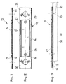
- Fig. 1
- in der Seitenansicht im Schnitt eine Fußschaltereinheit, die aus einem ersten plattenförmigen Element und aus einem damit integral verbundenen zweiten plattenförmigen Element besteht,
- Fig. 2
- eine Draufsicht auf das integrale plattenförmige Element gem. Fig. 1,
- Fig. 3
- einen Schnitt durch das integrale plattenförmige Element gem. Fig. 1 im auf einer Ladeplattform montierten Zustand unter Andeutung der elektrischen Verbindungsleitungen zu zwei auf der Fußschaltereinheit angeordneten fußbetätigbaren Schaltern,
- Fig. 4
- einen Schnitt durch eine Ladeplattform in Querrichtung, auf der das integrale, doppelt U-profilförmige plattenförmige Element in der Stirnansicht dargestellt ist und mit den Stegen in die Täler zwischen jeweils zwei von der Oberfläche der Ladeplattform vorspringenden Stegen eingesetzt ist, und
- Fig. 5
- in der Stirnansicht das doppelt U-profilförmig und integral ausgebildete plattenförmige Element im Schnitt.
- 10
- Fußschaltereinheit
- 11
- Ladeplattform
- 12
- Fußschalter
- 13
- Fußschalter
- 14
- plattenförmiges erstes Element (Gehäuse)
- 15
- Steg
- 16
- Steg
- 17
- Innenfläche
- 18
- Höhe (Steg-Element)
- 19
- Höhe (Steg-Ladeplattform)
- 20
- Steg
- 21
- Oberfläche erstes Element
- 22
- plattenförmiges zweites Element
- 23
- Öffnung
- 24
- Steg
- 25
- Steg
- 26
- Breite (Steg-Element)
- 27
- Breite Tal zwischen den Stegen
- 28
- Loch (Aufnahme-Fußschalter)
- 29
- Loch (Aufnahme-Fußschalter)
- 30
- Endbereich
- 31
- Endbereich
- 32
- Kabelverbindung
- 33
- Kabelverbindung
- 34
- Schraubenverbindung
- 35
- Schraubenverbindung
Claims (15)
- Fußschaltereinheit für Ladeplattformen von Ladebordwandsystemen für Fahrzeuge, mit denen die Ladeplattform durch entsprechende Betätigung von Fußschaltern zum Anheben und Absenken veranlaßt wird, umfassend ein Gehäuse, in dem die Fußschalter vorhanden sind, wobei das Gehäuse auf der Ladeplattform befestigbar ist, dadurch gekennzeichnet, daß das Gehäuse aus einem plattenförmigen Element (14) besteht.
- Fußschaltereinheit nach Anspruch 1, dadurch gekennzeichnet, daß das plattenförmige Element (14) einen U-profilförmigen Querschnitt aufweist.
- Fußschaltereinheit nach Anspruch 2, dadurch gekennzeichnet, daß die Stege (15, 16), bezogen auf die Innenfläche (17) des Elements (14), eine Höhe (18) entsprechend der Höhe (19) von von der Ladeplättform (11) vorspringenden Stegen (20) aufweisen.
- Fußschaltereinheit nach einem oder mehreren der Ansprüche 1 bis 3, dadurch gekennzeichnet, daß auf der Oberfläche (21) des Elements (14), die im befestigten Zustand der Ladeplattform (11) abgewendet ist, ein das Element (14) wenigstens teilweise bedeckendes zweites plattenförmiges Element (22) angeordnet ist.
- Fußschaltereinheit nach Anspruch 4, dadurch gekennzeichnet, daß das zweite plattenförmige Element (22) mit dem ersten plattenförmigen Element (14) integral ausgebildet ist.
- Fußschaltereinheit nach Anspruch 4, dadurch gekennzeichnet, daß das zweite plattenförmige Element (22) auf dem ersten plattenförmigen Element (14) befestigbar ist.
- Fußschaltereinheit nach einem oder mehreren der Ansprüche 1 bis 6, dadurch gekennzeichnet, daß das zweite plattenförmige Element (22) im Querschnitt U-profilförmig ausgebildet ist, wobei zwischen den dadurch gebildeten Stegen (24, 25) eine Öffnung (23) gebildet wird.
- Fußschaltereinheit nach Anspruch 7, dadurch gekennzeichnet, daß die Öffnung (23) zur Aufnahme von Markierungs- und/oder Hinweismitteln ausgeformt ist.
- Fußschaltereinheit nach einem oder mehreren der Ansprüche 1 bis 8, dadurch gekennzeichnet, daß die Schalter (12, 13) Mikroschalter sind.
- Fußschaltereinheit nach einem oder mehreren der Ansprüche 1 bis 8, dadurch gekennzeichnet, daß die Schalter (12, 13) Sensorschalter sind.
- Fußschaltereinheit nach einem oder mehreren der Ansprüche 1 bis 10, dadurch gekennzeichnet, daß die mit den Schaltern (12, 13) zusammenwirkenden elektrischen und/oder elektronischen Steuer- und/oder Regeleinrichtungen abgesetzt von der Fußschaltereinheit (12) angeordnet sind.
- Fußschaltereinheit nach einem oder mehreren der Ansprüche 1 bis 11, dadurch gekennzeichnet, daß das plattenförmige Element (14; 22) als lediglich abzulängendes Halbzeug bereitstellbar ist.
- Fußschaltereinheit nach einem oder mehreren der Ansprüche 1 bis 12, dadurch gekennzeichnet, daß wenigstens das erste plattenförmige Element (14) aus einem Leichtmetallwerkstoff besteht.
- Fußschaltereinheit nach einem oder mehreren der Ansprüche 1 bis 12, dadurch gekennzeichnet, daß wenigstens das erste plattenförmige Element (14) aus einem Kunststoffwerkstoff besteht.
- Fußschaltereinheit nach einem oder mehreren der Ansprüche 1 bis 12, dadurch gekennzeichnet, daß wenigstens das erste plattenförmige Element (14) aus einem Verbundwerkstoff besteht.
Priority Applications (1)
| Application Number | Priority Date | Filing Date | Title |
|---|---|---|---|
| EP01102677A EP1231104A1 (de) | 2001-02-07 | 2001-02-07 | Fussschaltereinheit für Ladeplattformen von Ladebordwandsystemen |
Applications Claiming Priority (1)
| Application Number | Priority Date | Filing Date | Title |
|---|---|---|---|
| EP01102677A EP1231104A1 (de) | 2001-02-07 | 2001-02-07 | Fussschaltereinheit für Ladeplattformen von Ladebordwandsystemen |
Publications (1)
| Publication Number | Publication Date |
|---|---|
| EP1231104A1 true EP1231104A1 (de) | 2002-08-14 |
Family
ID=8176406
Family Applications (1)
| Application Number | Title | Priority Date | Filing Date |
|---|---|---|---|
| EP01102677A Withdrawn EP1231104A1 (de) | 2001-02-07 | 2001-02-07 | Fussschaltereinheit für Ladeplattformen von Ladebordwandsystemen |
Country Status (1)
| Country | Link |
|---|---|
| EP (1) | EP1231104A1 (de) |
Citations (3)
| Publication number | Priority date | Publication date | Assignee | Title |
|---|---|---|---|---|
| DE3216398A1 (de) * | 1982-05-03 | 1983-11-03 | Wilhelm Stoll Maschinenfabrik Gmbh, 3325 Lengede | Ladebordwand mit plattform-fussschaltung |
| US5556250A (en) * | 1988-11-05 | 1996-09-17 | Ricon Corporation | Vehicle lifts |
| EP0960770A1 (de) * | 1998-05-26 | 1999-12-01 | Gerd Bär | Fusssteuerung für eine Hubladebühne |
-
2001
- 2001-02-07 EP EP01102677A patent/EP1231104A1/de not_active Withdrawn
Patent Citations (3)
| Publication number | Priority date | Publication date | Assignee | Title |
|---|---|---|---|---|
| DE3216398A1 (de) * | 1982-05-03 | 1983-11-03 | Wilhelm Stoll Maschinenfabrik Gmbh, 3325 Lengede | Ladebordwand mit plattform-fussschaltung |
| US5556250A (en) * | 1988-11-05 | 1996-09-17 | Ricon Corporation | Vehicle lifts |
| EP0960770A1 (de) * | 1998-05-26 | 1999-12-01 | Gerd Bär | Fusssteuerung für eine Hubladebühne |
Similar Documents
| Publication | Publication Date | Title |
|---|---|---|
| EP0700861B1 (de) | Hebebühne für Kraftfahrzeuge | |
| DE19643203A1 (de) | Vorrichtung an einer Lenksäule für Kraftfahrzeuge zur Längen- und/oder Höhen- bzw. Neigungsverstellung | |
| EP0956465B1 (de) | Kettenglied mit einschiebbaren trennstegen | |
| EP0864489B1 (de) | Bodenelement | |
| DE3934847A1 (de) | Transportable zerlegbare kabine | |
| EP3161915A1 (de) | Rollstuhlüberfahrt | |
| DE3529662A1 (de) | Leichtmetall-bordwand fuer ladeflaechen von kraftfahrzeugen | |
| EP2213347B1 (de) | Anhänger für ein Kinderfahrzeug | |
| DE2727575A1 (de) | Metallgitterrost sowie verfahren und vorrichtung zu seiner herstellung | |
| EP1645462B1 (de) | Fahrzeug | |
| EP1231104A1 (de) | Fussschaltereinheit für Ladeplattformen von Ladebordwandsystemen | |
| EP1279771A2 (de) | Fahrbahnbegrenzungseinrichtung | |
| DE602004006486T2 (de) | Verriegelungsmechanismus und ein damit ausgerüstetes Schiebedach | |
| DE102007050462A1 (de) | Führungsschiene | |
| EP2784222A1 (de) | Leitplankenvorrichtung, insbesondere Leitplankenüberleitungssystem, mit Verriegelungseinheit und Kurzabsenkung | |
| DE19712278A1 (de) | Bodenelement | |
| WO2022174954A1 (de) | Bügelscharniervorrichtung sowie hiermit ausgestatteter personenkraftwagen | |
| EP1119464A1 (de) | Ventil, insbesondere be- und entlüftungsventil für den innenraum eines kraftfahrzeuges | |
| EP0536547B1 (de) | Wagenheber | |
| DE102011053263A1 (de) | Leitschwellenschranke sowie Fahrzeugrückhaltesystem mit einer Leitschwellenschranke | |
| DE19707689C1 (de) | Kabelbrücke | |
| DE102016102312B4 (de) | Gehäuse für einen Laufradblock und Laufradblock hiermit | |
| DE10044779B4 (de) | Längseinstellbarer Fahrzeugsitz | |
| DE19831782C2 (de) | Sollbruchelement | |
| DE3822325C1 (de) |
Legal Events
| Date | Code | Title | Description |
|---|---|---|---|
| PUAI | Public reference made under article 153(3) epc to a published international application that has entered the european phase |
Free format text: ORIGINAL CODE: 0009012 |
|
| AK | Designated contracting states |
Kind code of ref document: A1 Designated state(s): AT BE CH CY DE DK ES FI FR GB GR IE IT LI LU MC NL PT SE TR |
|
| AX | Request for extension of the european patent |
Free format text: AL PAYMENT 20010301;LT PAYMENT 20010301;LV PAYMENT 20010301;MK PAYMENT 20010301;RO PAYMENT 20010301;SI PAYMENT 20010301 |
|
| 17P | Request for examination filed |
Effective date: 20030204 |
|
| AKX | Designation fees paid |
Designated state(s): AT BE CH CY DE DK ES FI FR GB GR IE IT LI LU MC NL PT SE TR |
|
| AXX | Extension fees paid |
Extension state: MK Payment date: 20010301 Extension state: SI Payment date: 20010301 Extension state: LT Payment date: 20010301 Extension state: RO Payment date: 20010301 Extension state: LV Payment date: 20010301 Extension state: AL Payment date: 20010301 |
|
| 17Q | First examination report despatched |
Effective date: 20040914 |
|
| STAA | Information on the status of an ep patent application or granted ep patent |
Free format text: STATUS: THE APPLICATION IS DEEMED TO BE WITHDRAWN |
|
| 18D | Application deemed to be withdrawn |
Effective date: 20060901 |