EP1231104A1 - Foot-operated switch unit for loading tailgate systems - Google Patents
Foot-operated switch unit for loading tailgate systems Download PDFInfo
- Publication number
- EP1231104A1 EP1231104A1 EP01102677A EP01102677A EP1231104A1 EP 1231104 A1 EP1231104 A1 EP 1231104A1 EP 01102677 A EP01102677 A EP 01102677A EP 01102677 A EP01102677 A EP 01102677A EP 1231104 A1 EP1231104 A1 EP 1231104A1
- Authority
- EP
- European Patent Office
- Prior art keywords
- plate
- switch unit
- foot switch
- shaped element
- unit according
- Prior art date
- Legal status (The legal status is an assumption and is not a legal conclusion. Google has not performed a legal analysis and makes no representation as to the accuracy of the status listed.)
- Withdrawn
Links
Images

Classifications
-
- B—PERFORMING OPERATIONS; TRANSPORTING
- B60—VEHICLES IN GENERAL
- B60P—VEHICLES ADAPTED FOR LOAD TRANSPORTATION OR TO TRANSPORT, TO CARRY, OR TO COMPRISE SPECIAL LOADS OR OBJECTS
- B60P1/00—Vehicles predominantly for transporting loads and modified to facilitate loading, consolidating the load, or unloading
- B60P1/44—Vehicles predominantly for transporting loads and modified to facilitate loading, consolidating the load, or unloading having a loading platform thereon raising the load to the level of the load-transporting element
- B60P1/4471—General means for controlling movements of the loading platform, e.g. hydraulic systems
Definitions
- the invention relates to a foot switch unit for Loading platforms of tail lift systems for vehicles, with which the loading platform by appropriate actuation caused by foot switches to raise and lower is comprising a housing in which the foot switch are present, with the housing on the loading platform is attachable.
- Foot switch units of this type come in a wide variety Variants used with loading platforms.
- Tail lift systems are regularly subject to a rough Handling by the operator operating the loading platform can be raised and lowered, especially if the operator with the load on the loading platform standing raising and lowering with your feet initiated via the foot switch.
- the previously known foot switch units are also designed such that they are on the operator side opposite side electronic and / or electrical Have control and / or regulating devices, which serve the purpose of that of the actual foot switches for lifting and lowering the tail lift prepare given electrical signals and to a control unit for the tail lift system in to convey its entirety.
- the foot switch units relatively massive, i.e. in your Thickness, based on the loading platform, very high and, also related to the loading platform, very wide to create a space on the back in which the electrical and / or electronic control and Control device can be accommodated, wherein this space to be created on the bottom or back the foot switch unit for the aforementioned purposes too still water-, dust-vapor-tight and the like.
- Encapsulated must be what additional space for the hermetic Encapsulation required.
- the above-mentioned high and massive education of the Housing of the foot switch device also has one Another significant disadvantage, especially if the foot switch unit in the case of so-called folding platforms trained loading platforms should be used and even if the loading platforms are in the form of so-called Refrigerated cases trained vehicle bodies used should be.
- the so-called folding loading platforms With the so-called folding loading platforms, the Loading platform folded during non-operation and in folded state under the rear of the cargo area of the vehicle moved.
- One in the clear height too large foot switch unit, as is known up to now, is for the support and the support of the loading platform elements extremely cumbersome when folded and measures must be taken to ensure that the Foot switch unit itself not directly on the part of the loading platform folded on it comes.
- the housing consists of a plate-shaped element.
- a housing plate-shaped element according to the invention both for Folding loading platforms as well as in connection with loading platforms, those with refrigerated cases as vehicle bodies are equipped to use as for both applications the thickness of the plate-like element so can be kept low that the door of the refrigerator even with the loading platform raised in the end position without Difficulty can be opened and closed and no impairment when used with folding loading platforms the folding options.
- the Solution according to the invention can be implemented very inexpensively and the solution according to the invention is simple on the Attachable loading platform.
- the plate-shaped element has a substantially U-shaped cross section, which increases stability of the plate-shaped element can be increased at simultaneous possibility of reducing the distance the levels of the plate, i.e. a decrease the thick.
- the webs point in relation to the inner surface or inner plane of the element if there is a U-shaped profile Cross section has a height corresponding to Height of webs protruding from the loading platform.
- a variety of loading platforms have a profiled Surface cross-section, i.e. from the surface There are webs on the loading platform, i.e. away from the loading platform.
- the averted when the loading platform is fastened is at least partially covering the element second element arranged.
- This second plate-shaped Element where the distance between the two is essentially parallel planes also small compared to the other dimensions, i.e. the thickness of the plate is small, has the task of a certain separation between e.g. from at both ends of the first plate-shaped element arranged foot switches to effect.
- the second plate-shaped element also causes Goods placed on the foot switch unit in error cannot trigger the foot switch, because the second plate-shaped element sets for it Obstacle.
- the second plate-shaped element can preferably also be used the first plate-shaped element integrally formed be, i.e. be made from one piece, but it is also preferably possible, the second plate-shaped Element on the first plate-shaped element attach, i.e. to train beforehand as a separate part, and then, for example, by means of screw connections on the to attach the first plate-shaped element.
- the second plate-shaped element can, similar to that first plate-shaped element, acc. another advantageous embodiment of the foot switch unit in Cross-section essentially U-shaped be, one between the webs thus formed flat opening corresponding to the inner opening between the webs of the first plate-shaped element becomes.
- This measure can also be used for reduction the thickness of the second plate-shaped element Stability can be achieved, i.e. also i.V.m. the correspondingly U-shaped first plate-shaped element.
- marking and / or information means can be provided the operator of the foot switch unit Notes on the foot switches to be operated via the Giving and lowering the loading platform and if necessary also Warning notices regarding possible incorrect actuation options.
- foot switch of the foot switch unit very much be flat so that they are essentially as possible not thicker or higher than the first plate-shaped Element are.
- foot-operated switch preferably microswitch or preferably sensor switches compared in the trade for their lateral expansion with small thicknesses are available and also encapsulate slightly waterproof leave or already in waterproof and dustproof configuration Tobe offered.
- the foot-operated ones are advantageous Interacting electrical and / or switches electronic control and / or regulating devices arranged away from the foot switch unit, i.e. it need according to the invention in the loading platform on site no openings for fastening the foot switch unit be provided in which, as in some cases so far, space had to be provided to the previously shown funds to be able to accommodate.
- the preferred one Design of the foot switch unit also has the Advantage that the foot switch unit only with respect of the foot-operated switch with corresponding advanced electrical lines are connected have to.
- the regulation and / or control of lifting, Lowering and possibly folding or collapsing the Loading platform takes place centrally from a corresponding one Control unit on the vehicle for the operator accessible place is arranged.
- the solution of the invention downright offers the plate-shaped element in strip-shaped To have lengths produced as semi-finished products and this preferably only in the desired dimension cut to length, i.e. in a simple way to the desired one Length corresponding to the overall dimension of the tail lift system adapt and thus in a simple way different designs of the tail lift system to be able to adapt.
- the plate-shaped element has any suitable mechanical and resistant to environmental influences It is advantageous to use material, at least the plate-shaped element made of a light metal material produce the one hand high strength and on the other hand, a low weight and also suitable Alloy high resistance to Environmental influences such as rain, ice, salt, dust, fuel vapors and the like.
- first plate-shaped element preferably made of one Form plastic material or preferably at least the first plate-shaped element from one Manufacture composite, or analogously at integral training the first plate-shaped element and the second plate-shaped member made of the same
- first plate-shaped element possibly even different Materials for the respective plate-shaped element for example depending on the expected wear and tear parameters to choose.
- Foot switch unit 10 with two foot switches as an example 12, 13 is described equipped.
- foot switch units 10 for the intended Purpose known, the more than two foot switches 12, 13th have and it is also conceivable the foot switch unit 10 only with a foot switch 12; 13 to train. All of these designs are from the solution proposed according to the invention includes, since the constructive principle of the foot switch unit 10 does not change.
- the housing of the foot switch unit 10 comprises a first one plate-shaped element 14 and a second plate-shaped Element 22, in the embodiment shown here the foot switch unit 10 integrally with each other are trained.
- Both the first plate-shaped Element 14 as well as the second plate-shaped element 22 have a substantially U-shaped profile Cross-section on, cf. Fig. 5.
- the inner plane or inner surface 17 delimiting webs 15, 16 of the first plate-shaped element 14 are in opposite directions Direction with the second "plate-shaped" element its webs 24, 25 delimiting the opening 23 from one another path.
- the height 18 of the webs 15, 16 corresponds For example, the height 19 of webs 20 on the surface a loading platform 11 substantially parallel to each other are arranged at a distance, cf. Fig. 4.
- the Width 26 of the webs 15, 16 corresponds approximately to the width 27 of the valley between two webs 20 each the surface of the loading platform 11 is formed. So can with a correspondingly dimensioned overall width of the first plate-shaped element 14 this with its two webs 15, 16 in a respective valley between two Ridges 20 of the plate-shaped element engage and is there in relation to the representation of FIG. 4 lateral shift fixed.
- the height 19 of the webs 20 the loading platform 11 corresponds essentially to the height 18 of the first plate-shaped element 14, based on FIG the inner plane or inner surface 17 between the both of these protruding webs 15, 16.
- the first plate-shaped element 14 with its inner surface 14 rest on the webs 20 of the loading platform 11.
- second plate-shaped element 22 covers the first plate-shaped element 14 only partially, cf. the 1 to 3.
- second plate-shaped element 22 not formed, i.e. here the flat surface 21 forms a flat one Paragraph and serves to accommodate the foot switches 12, 13, the appropriately in holes formed there 28, 29 are included, cf. also Fig. 3.
- the integrally formed first and second plate-shaped Element 14, 22 can be in the form of a semi-finished product appropriately trained extruded profile are, for example. From a suitably chosen metal or a suitably selected metal alloy, the both in relation to the representation of FIGS. 1 to 3 left and right end regions 30, 31, for example Milling can be processed appropriately, so that the Continuous casting profile also originally trained there corresponding end regions of the plate-shaped Elements 22 are removed. This is with the integral Formation of the first plate-shaped element 14 with the second plate-shaped element 22 the only one essential mechanical processing that is necessary.
- marking and / or information means can be provided the operator the necessary Notes on the operation of foot switches 12, 13 and Loading platform 11 can give and if necessary also Warnings to ensure proper Operation.
- the two webs delimiting the opening 23 24, 25 also prevent the operator from using your footwear the marking and / or information damage and can therefore make it unrecognizable.
- the foot switches 12, 13, cf. Fig. 3 have one low height on the one hand from the surface 21 of the first plate-shaped element 14 in the end regions 30, 31 protrude only slightly so that they can still be operated with the operator's foot, and they stand down, based on the representation 3, i.e. towards the loading platform 14, only slightly into this, so that only there small holes for receiving the corresponding part of the Foot switches 12, 13 are to be provided.
- the cable connections 32, 33 with the foot switches 12, 13 are with arranged away from the foot switch unit 12 electrical and / or electronic control and / or Control devices connected (not shown) that centrally on a vehicle on which the tail lift system is arranged with the loading platform 11 are provided and from there also a normal manual operation allow the loading platform 11 when, for example, the loading process discharge process can be started or ended should.
- suitable screw connections 34, 35 see. Fig. 2, the foot switch unit 10 on the Loading platform 11 are attached.
- the screw connections 24, 25 can also serve at the same time second plate-shaped element 21 with the first plate-shaped Element 14 to connect if both elements 14, 22 not integrally but as separate parts are manufactured and only in the course of assembly on the Loading platform 11 are to be connected.
Landscapes
- Engineering & Computer Science (AREA)
- Transportation (AREA)
- Mechanical Engineering (AREA)
- Switch Cases, Indication, And Locking (AREA)
Abstract
Description
Die Erfindung betrifft eine Fußschaltereinheit für Ladeplattformen von Ladebordwandsystemen für Fahrzeuge, mit denen die Ladeplattform durch entsprechende Betätigung von Fußschaltern zum Anheben und Absenken veranlaßt wird, umfassend ein Gehäuse, in dem die Fußschalter vorhanden sind, wobei das Gehäuse auf der Ladeplattform befestigbar ist.The invention relates to a foot switch unit for Loading platforms of tail lift systems for vehicles, with which the loading platform by appropriate actuation caused by foot switches to raise and lower is comprising a housing in which the foot switch are present, with the housing on the loading platform is attachable.
Fußschaltereinheiten dieser Art werden in den unterschiedlichsten Varianten bei Ladeplattformen eingesetzt. Ladebordwandsysteme unterliegen regelmäßig einer rauhen Handhabung durch die Bedienungsperson, die die Ladeplattform anheben und absenken läßt, insbesondere dann, wenn die Bedienungsperson mit der Last auf der Ladeplattform stehend das Anheben und Absenken mit den Füßen über die Fußschalter veranlaßt. Aus diesem Grunde sind bisherige Fußschaltereinheiten verhältnismäßig massiv ausgebildet, d.h. sie weisen regelmäßig ein Fußschaltergehäuse auf, das dem rauhen Handhabungsbetrieb standzuhalten vermag, zumal auch durch entsprechend massiven Aufbau Sorge dafür getragen werden muß, daß die Fußschaltereinheit auch beim unbeabsichtigten Verrutschen von Gütern auf die Fußschaltereinheit oder das versehentliche Absetzen von Gütern auf der Fußschaltereinheit diese keinen Schaden nimmt, d.h. die darin untergebrachten Fußschalter nicht in ihrer Funktion gestört werden.Foot switch units of this type come in a wide variety Variants used with loading platforms. Tail lift systems are regularly subject to a rough Handling by the operator operating the loading platform can be raised and lowered, especially if the operator with the load on the loading platform standing raising and lowering with your feet initiated via the foot switch. This is why previous foot switch units relatively solid trained, i.e. they regularly feature a foot switch housing on the rough handling operation is able to withstand, especially by correspondingly massive construction care must be taken that the Foot switch unit even if it slips accidentally of goods on the foot switch unit or that accidental depositing of goods on the foot switch unit it is not damaged, i.e. the ones in it housed foot switch not in their function be disturbed.
Die bisher bekannten Fußschaltereinheiten sind zudem derart ausgestaltet, daß sie auf ihrer der Bedienungsseite abgewandten Seite elektronische und/oder elektrische Steuer- und/oder Regeleinrichtungen aufweisen, die dem Zwecke dienen, die von den eigentlichen Fußschaltern zum Heben und Absenken der Ladebordwand gegebenen elektrischen Signale geeignet aufbereiten und an eine Steuereinheit für das Ladebordwandsystem in seiner Gesamtheit zu übermitteln. Durch diese Maßnahmen, wie sie bisher vorgenommen wurden, sind die Fußschaltereinheiten verhältnismäßig massiv, d.h. in ihrer Dicke, bezogen auf die Ladeplattform, sehr hoch ausgebildet und, ebenfalls bezogen auf die Ladeplattform, sehr breit, um auf der Rückseite einen Raum zu schaffen, in dem die elektrische und/oder elektronische Steuerund Regeleinrichtung untergebracht werden kann, wobei dieser an der Unter- bzw. Rückseite zu schaffende Raum der Fußschaltereinheit für die vorgenannten Zwecke auch noch wasser-, staub- dampfdicht und dergl. gekapselt sein muß, was zusätzlichen Raum für die hermetische Kapselung erfordert. The previously known foot switch units are also designed such that they are on the operator side opposite side electronic and / or electrical Have control and / or regulating devices, which serve the purpose of that of the actual foot switches for lifting and lowering the tail lift prepare given electrical signals and to a control unit for the tail lift system in to convey its entirety. Through these measures, as they have been done so far are the foot switch units relatively massive, i.e. in your Thickness, based on the loading platform, very high and, also related to the loading platform, very wide to create a space on the back in which the electrical and / or electronic control and Control device can be accommodated, wherein this space to be created on the bottom or back the foot switch unit for the aforementioned purposes too still water-, dust-vapor-tight and the like. Encapsulated must be what additional space for the hermetic Encapsulation required.
Die vorbeschriebene hohe und massive Ausbildung des Gehäuses der Fußschaltereinrichtung hat zudem einen weiteren erheblichen Nachteil, insbesondere dann, wenn die Fußschaltereinheit bei als sog. Faltplattformen ausgebildeten Ladeplattformen eingesetzt werden soll und auch dann, wenn die Ladeplattformen bei in Form von sog. Kühlkoffern ausgebildeten Fahrzeugkarosserien eingesetzt werden sollen. Bei den sog. Faltladeplattformen wird die Ladeplattform während des Nichtbetriebes gefaltet und im gefalteten Zustand unter den Heckbereich der Ladefläche des Fahrzeugs verschoben. Eine in der lichten Höhe zu große Fußschaltereinheit, wie sie bisher bekannt ist, ist für den Halt und die Auflagerung der Ladeplattformelemente im zusammengeklappten Zustand äußerst hinderlich und es müssen Maßnahmen ergriffen werden, daß die Fußschaltereinheit selbst nicht unmittelbar auf den darauf geklappten Teil der Ladeplattform zu liegen kommt. Bei Fahrzeugkarosserien in Form der genannten Kühlkoffer ist zum Erhalt einer gekühlten Atmosphäre im Kühlkoffer, anders als bei normalen Kraftfahrzeug-Karosserien für Stückgut und dgl., eine gesonderte rückwärtige Tür vorhanden. Da diese Tür zum leichten Entladen und Beladen des Kühlkoffers zum Boden hin schwellenfrei sein muß, weißt die den Kühlkoffer abschließende Tür nur eine geringfügige Freiheit oberhalb der Ladeplattform auf, wenn die Ladeplattform sich in angehobener Stellung befindet. Die bekannten Fußschaltereinheiten mit der beschriebenen, erheblichen lichten Höhe erzwingen somit, daß die Ladeplattform, damit die Tür des Kühlkoffers überhaupt gehöffnet und geschlossen werden kann, zunächst ein Anheben der Ladeplattform so hoch, daß die Tür des Kühlkoffers "über" die Fußschaltereinheit gerade noch geschwenkt werden kann und dann ein weiteres Anheben, bis die Ladeplattform sich auf dem Niveau der Ladefläche des Kühlkoffers befindet. Diese Handhabung ist, da sie auch im umgekehrten Falle des Schließens der Tür des Kühlkörpers derart vonstatten gehen muß, äußerst umständlich und bedienerunfreundlich.The above-mentioned high and massive education of the Housing of the foot switch device also has one Another significant disadvantage, especially if the foot switch unit in the case of so-called folding platforms trained loading platforms should be used and even if the loading platforms are in the form of so-called Refrigerated cases trained vehicle bodies used should be. With the so-called folding loading platforms, the Loading platform folded during non-operation and in folded state under the rear of the cargo area of the vehicle moved. One in the clear height too large foot switch unit, as is known up to now, is for the support and the support of the loading platform elements extremely cumbersome when folded and measures must be taken to ensure that the Foot switch unit itself not directly on the part of the loading platform folded on it comes. For vehicle bodies in the form of the above Refrigerator is to maintain a cool atmosphere in the Refrigerator, unlike normal motor vehicle bodies for general cargo and the like, a separate rear Door available. Because this door for easy unloading and loading the refrigerated case to the floor without thresholds must be known, the one that closes the refrigerator Door only a slight freedom above the loading platform on when the loading platform is in raised Position. The well-known foot switch units with the described, significant clear height thus force the loading platform to allow the door opened and closed the refrigerator at all can be, first lifting the loading platform like this high that the door of the refrigerator "over" the foot switch unit can just be swiveled and then another lift until the loading platform is on the Level of the cargo area of the refrigerator is located. This Handling is because they are also in the reverse case of Do this by closing the heat sink door must go, extremely cumbersome and user-unfriendly.
Schließlich sind die vorangehend beschriebenen, im Stand der Technik bekannten Gehäuse der Fußschaltereinheiten und damit die Fußschaltereinheiten schlechthin, nur sehr kostenträchtig herstellbar, da sie regelmäßig eine spezielle Ausgestaltung erfordern, sei es in Form eines speziell modellierten und gefertigten metallischen Gehäuses, das aus Spritz- bzw. Druckguß besteht, sei es in Form eines derartigen Gehäuses, das zudem den besagten Hohlraum für die elektrischen und/oder elektronischen Steuerungs- und/oder Regelungsmittel aufweist, wobei noch hinzu kommt, daß, um derartige bekannte Fußschaltereinheiten überhaupt durch die bzw. an der Ladeplattform aufnahmefähig zu machen bzw. befestigen zu können, die Ladeplattform an der Stelle der Befestigung der Fußschaltereinheit auf der Ladeplattform auf aufwendige Weise durch Herstellung von Aufnahmelöchern bearbeitet werden muß, wodurch zudem noch zumindest eine örtliche Schwächung der Ladeplattform nachteiligerweise erreicht wird.Finally, those described above are in the state known technology of the housing of the foot switch units and thus the foot switch units par excellence, only very much costly to produce, since they regularly have a require special design, be it in the form of a specially modeled and manufactured metallic Housing, which consists of injection or die casting, be it in the form of such a housing, which also said Cavity for the electrical and / or electronic Has control and / or regulating means, in addition to that, to such known Foot switch units at all through the To make loading platform receptive or to fasten can, the loading platform at the point of attachment the foot switch unit on the loading platform on elaborate Way by making receiving holes must be edited, which also means at least one local weakening of the loading platform disadvantageously is achieved.
Es ist deshalb Aufgabe der vorliegenden Erfindung, eine Fußschaltereinheit der eingangs genannten Art zu schaffen, mit der eine sehr geringe Höhe, d.h. ein sehr geringes Auftragen oberhalb der Ladeplattform erreichbar ist, auf der das Gehäuse der erfindungsgemäßen Fußschaltereinheit aufgebracht werden soll, die einfach und kostengünstig herstellbar sein soll, die keine Durchlöcherung der Ladeplattform zum Zwecke ihrer Montage erfordert, die dennoch dem rauhen Handhabungsbetrieb von Ladeplattformen standhält und zudem ggf. noch eine mechanische Verstärkung der Ladeplattform und damit eine größere Belastbarkeit der Ladeplattform ermöglicht, wobei die erfindungsgemäße Fußschaltereinheit sowohl bei Faltladeplattformen als auch bei in Form von Kühlkoffern ausgebildeten Karosserien von Fahrzeugen gleichermaßen gut eingesetzt werden kann und einen vom normalen Betrieb der Ladeplattform nicht abweichenden Anhebe- und Absenkbetrieb auch bei als Kühlkoffern ausgebildeten Fahrzeugkarosserien ermöglicht.It is therefore an object of the present invention to To create a foot switch unit of the type mentioned at the beginning, with a very low height, i.e. a very low application above the loading platform is on the housing of the foot switch unit according to the invention should be applied that simple and Should be inexpensive to manufacture, the no perforation the loading platform for the purpose of its assembly requires that the rough handling operation of Load platforms withstands and possibly also one mechanical reinforcement of the loading platform and thus a enables greater loading capacity of the loading platform, the foot switch unit according to the invention both at Folding loading platforms as well as in the form of refrigerated cases trained bodies of vehicles alike can be used well and one of the normal Operation of the loading platform not deviating lifting and Lowering operation also with refrigerated cases Vehicle bodies enabled.
Gelöst wird die Aufgabe gem. der Erfindung dadurch, daß das Gehäuse aus einem plattenförmigen Element besteht.The task is solved according to the invention in that the housing consists of a plate-shaped element.
Mittels der erfindungsgemäßen Lösung ist der bisher im Stand der Technik in der einen oder der anderen Form vorgegebene konstruktive Weg der Ausgestaltung des Gehäuses der Fußschaltereinheit vollständig verlassen worden. Anstelle aufwendiger Metallspritzgußkonstruktionen, die im Vorwege einen aufwendigen und kostenträchtigen Bau einer Form als Spritzgußform erfordern, wird erfindungsgemäß lediglich ein plattenförmiges Element verwendet, das definitionsgemäß im wesentlichen durch einen durch zwei im wesentlichen parallele Ebenen begrenzten Körper gebildet wird, wobei der Abstand dieser Ebenen, d.h. die Dicke, klein im Vergleich zu den anderen Maßen ist. Es ist somit möglich, als Gehäuse das erfindungsgemäße plattenförmige Element sowohl für Faltladeplattformen als auch im Zusammenhang mit Ladeplattformen, die mit Kühlkoffern als Fahrzeugkarosserien ausgerüstet sind, zu verwenden, da für beide Anwendungsfälle die Dicke des plattenförmigen Elements so gering gehalten werden kann, daß die Tür des Kühlkoffers auch bei in Endstellung angehobener Ladeplattform ohne Schwierigkeit geöffnet und geschlossen werden kann und bei Anwendung bei Faltladeplattformen keine Beeinträchtigung der Faltmöglichkeiten erfolgt. Zudem ist die erfindungsgemäße Lösung sehr preisgünstig realisierbar und die erfindungsgemäße Lösung ist einfach auf der Ladeplattform befestigbar.By means of the solution according to the invention is so far State of the art in one form or another predetermined constructive way of designing the Leave the foot switch unit housing completely Service. Instead of complex metal injection molding designs, in advance a complex and costly Building a mold as an injection mold will require according to the invention only a plate-shaped element used, which by definition essentially by one through two substantially parallel planes limited body is formed, the distance of these levels, i.e. the thickness, small compared to the other dimensions. It is therefore possible as a housing plate-shaped element according to the invention both for Folding loading platforms as well as in connection with loading platforms, those with refrigerated cases as vehicle bodies are equipped to use as for both applications the thickness of the plate-like element so can be kept low that the door of the refrigerator even with the loading platform raised in the end position without Difficulty can be opened and closed and no impairment when used with folding loading platforms the folding options. In addition, the Solution according to the invention can be implemented very inexpensively and the solution according to the invention is simple on the Attachable loading platform.
Gem. einer vorteilhaften Ausgestaltung der Erfindung weist das plattenförmige Element einen im wesentlichen U-profilförmigen Querschnitt auf, wodurch die Stabilität des plattenförmigen Elementes erhöht werden kann bei gleichzeitiger Möglichkeit der Verringerung des Abstandes der Ebenen der Platte, d.h. eine Verringerung der Dicke. Die Stege weisen, bezogen auf die Innenfläche bzw. Innenebene des Elements, wenn es einen U-profilförmigen Querschnitt aufweist, eine Höhe entsprechend der Höhe von der Ladeplattform vorspringenden Stegen auf. Eine Vielzahl von Ladeplattformen weisen einen profilierten Oberflächenquerschnitt auf, d.h. von der Oberfläche der Ladeplattform stehen Stege nach oben, d.h. von der Ladeplattform weg, hervor. Die Stege des plattenförmigen Elements greifen somit in die jeweiligen Täler zwischen zwei vorstehenden Stegen, so daß das plattenförmige Element mit seiner Innenoberfläche bzw. Innenebene auf den Stegen, die sich von der Oberfläche der Ladebordwand erheben bzw. vorstehen, aufliegt. Dadurch wird die Auftragdicke des plattenförmigen Elements bei größtmöglicher Stabilität auf das irgendwie mögliche Minimum begrenzt. Dadurch, daß die Stege des plattenförmigen Elements in die Stegtäler zwischen zwei Stegen der Ladeplattform eingreifen, wird das plattenförmige Element auch in bezug auf seinen Sitz relativ zur Ladeplattform in hohem Maße stabilisiert und fixiert.According to an advantageous embodiment of the invention the plate-shaped element has a substantially U-shaped cross section, which increases stability of the plate-shaped element can be increased at simultaneous possibility of reducing the distance the levels of the plate, i.e. a decrease the thick. The webs point in relation to the inner surface or inner plane of the element if there is a U-shaped profile Cross section has a height corresponding to Height of webs protruding from the loading platform. A variety of loading platforms have a profiled Surface cross-section, i.e. from the surface There are webs on the loading platform, i.e. away from the loading platform. The webs of the plate-shaped Elements thus intervene in the respective Valleys between two protruding ridges, so that plate-shaped element with its inner surface or Inner plane on the webs, which is from the surface raise or protrude the tail lift. This will make the plate thickness of the board Elements with the greatest possible stability on that somehow possible minimum is limited. The fact that the webs of plate-shaped element in the land valleys between two If the loading platform engages, the plate-shaped Element also relative to its seat highly stabilized and fixed to the loading platform.
Gem. einer weiteren vorteilhaften Ausgestaltung der Fußschaltereinheit wird auf der Oberfläche des Elements, die im befestigten Zustand der Ladeplattform abgewendet ist, ein das Element wenigstens teilweise bedeckendes zweites Element angeordnet. Dieses zweite plattenförmige Element, bei dem der Abstand der beiden im wesentlichen parallelen Ebenen ebenfalls klein im Vergleich zu den anderen Maßen ist, d.h. die Dicke der Platte gering ist, hat die Aufgabe, eine gewisse Trennung zwischen bspw. von an beiden Enden des ersten plattenförmigen Elements angeordneten Fußschaltern zu bewirken. Des weiteren bewirkt das zweite plattenförmige Element auch, daß irrtümlich auf der Fußschaltereinheit abgestellte Güter die Auslösung des Fußschalters nicht veranlassen können, denn das zweite plattenförmige Element stellt dafür ein Hindernis dar.According to a further advantageous embodiment of the Footswitch unit is on the surface of the element, the averted when the loading platform is fastened is at least partially covering the element second element arranged. This second plate-shaped Element where the distance between the two is essentially parallel planes also small compared to the other dimensions, i.e. the thickness of the plate is small, has the task of a certain separation between e.g. from at both ends of the first plate-shaped element arranged foot switches to effect. Furthermore the second plate-shaped element also causes Goods placed on the foot switch unit in error cannot trigger the foot switch, because the second plate-shaped element sets for it Obstacle.
Vorzugsweise kann das zweite plattenförmige Element mit dem ersten plattenförmigen Element integral ausgebildet sein, d.h. aus einem Stück gefertigt sein, es ist aber auch vorzugsweise möglich, das zweite plattenförmige Element auf dem ersten plattenförmigen Element zu befestigen, d.h. zuvor als gesondertes Teil auszubilden, und dann bspw. mittels Schraubverbindungen auf dem ersten plattenförmigen Element zu befestigen.The second plate-shaped element can preferably also be used the first plate-shaped element integrally formed be, i.e. be made from one piece, but it is also preferably possible, the second plate-shaped Element on the first plate-shaped element attach, i.e. to train beforehand as a separate part, and then, for example, by means of screw connections on the to attach the first plate-shaped element.
Auch das zweite plattenförmige Element kann, ähnlich dem ersten plattenförmigen Element, gem. einer weiteren vorteilhaften Ausgestaltung der Fußschaltereinheit im Querschnitt im wesentlichen U-profilförmig ausgebildet sein, wobei zwischen den dabei gebildeten Stegen eine flache Öffnung entsprechend der Innenöffnung zwischen den Stegen des ersten plattenförmigen Elements gebildet wird. Auch durch diese Maßnahme kann bei Verminderung der Dicke des zweiten plattenförmigen Elements eine Erhöhung der Stabilität erreicht werden, d.h. auch i.V.m. dem entsprechend U- profilförmig ausgebildeten ersten plattenförmigen Element. In der flachen Öffnung zwischen den Stegen des zweiten plattenförmigen Elements können bspw. Markierungs- und/oder Hinweismittel vorgesehen werden, die dem Bediener der Fußschaltereinheit Hinweise auf die zu betätigenden Fußschalter über das Heben und Senken der Ladeplattform geben und ggf. auch Warnhinweise in bezug auf mögliche Fehlbetätigungsmöglichkeiten.The second plate-shaped element can, similar to that first plate-shaped element, acc. another advantageous embodiment of the foot switch unit in Cross-section essentially U-shaped be, one between the webs thus formed flat opening corresponding to the inner opening between the webs of the first plate-shaped element becomes. This measure can also be used for reduction the thickness of the second plate-shaped element Stability can be achieved, i.e. also i.V.m. the correspondingly U-shaped first plate-shaped element. In the flat opening between the webs of the second plate-shaped element For example, marking and / or information means can be provided the operator of the foot switch unit Notes on the foot switches to be operated via the Giving and lowering the loading platform and if necessary also Warning notices regarding possible incorrect actuation options.
Im Lichte des vorangehend Gesagten müssen auch die eigentlichen Fußschalter der Fußschaltereinheit sehr flach ausgebildet sein, damit sie möglichst im wesentlichen nicht dicker bzw. höher als das erste plattenförmige Element sind. Zu diesem Zwecke eignen sich als fußbetätigbare Schalter vorzugsweise Mikroschalter oder vorzugsweise Sensorschalter, die im Handel im Vergleich zu ihrer lateralen Ausdehnung mit geringen Dicken verfügbar sind und sich zudem leicht wasserdicht kapseln lassen bzw. schon in wasser- und staubdichter Konfiguration angeboten werden.In the light of the foregoing, these too actual foot switch of the foot switch unit very much be flat so that they are essentially as possible not thicker or higher than the first plate-shaped Element are. For this purpose are suitable as foot-operated switch preferably microswitch or preferably sensor switches compared in the trade for their lateral expansion with small thicknesses are available and also encapsulate slightly waterproof leave or already in waterproof and dustproof configuration Tobe offered.
Vorteilhafterweise sind die mit den fußbetätigbaren Schaltern zusammenwirkenden elektrischen und/oder elektronischen Steuer- und/oder Regeleinrichtungen abgesetzt von der Fußschaltereinheit angeordnet, d.h. es brauchen erfindungsgemäß in der Ladeplattform am Orte der Befestigung der Fußschaltereinheit keine Öffnungen vorgesehen werden, in denen, wie teilweise bisher, Platz vorgesehen werden mußte, um die voraufgezeigten Mittel unterbringen zu können. Die vorzugsweise vorgeschlagene Ausgestaltung der Fußschaltereinheit hat zudem den Vorteil, daß die Fußschaltereinheit lediglich bezüglich der fußbetätigbaren Schalter mit entsprechenden herangeführten elektrischen Leitungen verbunden werden müssen. Die Regelung und/oder Steuerung des Hebens, Absenkens und ggf. Klappens bzw. Zusammenklappens der Ladeplattform erfolgt zentral von einer entsprechenden Steuereinheit, die am Fahrzeug an für die Bedienungsperson zugänglicher Stelle angeordnet ist.The foot-operated ones are advantageous Interacting electrical and / or switches electronic control and / or regulating devices arranged away from the foot switch unit, i.e. it need according to the invention in the loading platform on site no openings for fastening the foot switch unit be provided in which, as in some cases so far, space had to be provided to the previously shown funds to be able to accommodate. The preferred one Design of the foot switch unit also has the Advantage that the foot switch unit only with respect of the foot-operated switch with corresponding advanced electrical lines are connected have to. The regulation and / or control of lifting, Lowering and possibly folding or collapsing the Loading platform takes place centrally from a corresponding one Control unit on the vehicle for the operator accessible place is arranged.
Wie eingangs dargestellt, ist es ein wesentliches Element der Aufgabe und Lösung der Erfindung eine preisgünstige Ausgestaltung der Fußschaltereinheit zu schaffen, wobei die Lösung der Erfindung es geradezu anbietet, das plattenförmige Element in streifenförmigen Längen als Halbzeug herstellen zu lassen und dieses vorzugsweise lediglich in der gewünschten Dimension abzulängen, d.h. auf einfache Weise auf die gewünschte Länge entsprechend der Gesamtdimension des Ladebordwandsystems anzupassen und somit auf einfache Weise an unterschiedlicher Ausgestaltungen des Ladebordwandsystems anpassen zu können.As stated at the beginning, it is an essential one Element of the object and solution of the invention inexpensive design of the foot switch unit create, the solution of the invention downright offers the plate-shaped element in strip-shaped To have lengths produced as semi-finished products and this preferably only in the desired dimension cut to length, i.e. in a simple way to the desired one Length corresponding to the overall dimension of the tail lift system adapt and thus in a simple way different designs of the tail lift system to be able to adapt.
Obwohl es grundsätzlich möglich ist, als Werkstoff für das plattenförmige Element einen beliebigen geeigneten, mechanisch und gegen Umwelteinflüsse widerstandsfähigen Werkstoff zu verwenden, ist es vorteilhaft, wenigstens das plattenförmige Element aus einem Leichtmetallwerkstoff herzustellen, der einerseits hohe Festigkeit und andererseits ein geringes Gewicht und auch bei geeigneter Legierung eine hohe Widerstandsfähigkeit gegen Umwelteinflüsse wie Regen, Eis, Salz, Staub, Kraftstoffdämpfe und dgl. hat.Although it is basically possible as a material for the plate-shaped element has any suitable mechanical and resistant to environmental influences It is advantageous to use material, at least the plate-shaped element made of a light metal material produce the one hand high strength and on the other hand, a low weight and also suitable Alloy high resistance to Environmental influences such as rain, ice, salt, dust, fuel vapors and the like.
Grundsätzlich ist es aber auch möglich, wenigstens das erste plattenförmige Element, vorzugsweise aus einem Kunststoffwerkstoff auszubilden oder vorzugsweise wenigstens das erste plattenförmige Element aus einem Verbundwerkstoff herzustellen, oder sinngemäß bei integraler Ausbildung das erste plattenförmige Element und das zweite plattenförmige Element aus dem gleichen Werkstoff bestehen zu lassen, bei gesonderter Ausbildung des ersten plattenförmigen Elements und des zweiten plattenförmigen Elements ggf. sogar unterschiedliche Werkstoffe für das jeweilige plattenförmige Element bspw. in Abhängigkeit der zu erwartenden Be- und Abnutzungsparameter zu wählen.Basically, it is also possible, at least that first plate-shaped element, preferably made of one Form plastic material or preferably at least the first plate-shaped element from one Manufacture composite, or analogously at integral training the first plate-shaped element and the second plate-shaped member made of the same To leave material with separate training of the first plate-shaped element and the second plate-shaped element possibly even different Materials for the respective plate-shaped element for example depending on the expected wear and tear parameters to choose.
Die Erfindung wird nun unter Bezugnahme auf die nachfolgenden schematischen Zeichnungen anhand eines Ausführungsbeispieles eingehend beschrieben. Darin zeigen:
- Fig. 1
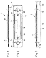
- in der Seitenansicht im Schnitt eine Fußschaltereinheit, die aus einem ersten plattenförmigen Element und aus einem damit integral verbundenen zweiten plattenförmigen Element besteht,
- Fig. 2
- eine Draufsicht auf das integrale plattenförmige Element gem. Fig. 1,
- Fig. 3
- einen Schnitt durch das integrale plattenförmige Element gem. Fig. 1 im auf einer Ladeplattform montierten Zustand unter Andeutung der elektrischen Verbindungsleitungen zu zwei auf der Fußschaltereinheit angeordneten fußbetätigbaren Schaltern,
- Fig. 4
- einen Schnitt durch eine Ladeplattform in Querrichtung, auf der das integrale, doppelt U-profilförmige plattenförmige Element in der Stirnansicht dargestellt ist und mit den Stegen in die Täler zwischen jeweils zwei von der Oberfläche der Ladeplattform vorspringenden Stegen eingesetzt ist, und
- Fig. 5
- in der Stirnansicht das doppelt U-profilförmig und integral ausgebildete plattenförmige Element im Schnitt.
- Fig. 1
- FIG. 2 shows a side view in section of a foot switch unit which consists of a first plate-shaped element and a second plate-shaped element integrally connected to it,
- Fig. 2
- a plan view of the integral plate-shaped element acc. Fig. 1
- Fig. 3
- a section through the integral plate-shaped element acc. 1 in the mounted state on a loading platform, indicating the electrical connection lines to two foot-operated switches arranged on the foot switch unit,
- Fig. 4
- a section through a loading platform in the transverse direction, on which the integral, double U-shaped plate-shaped element is shown in the front view and is inserted with the webs in the valleys between two webs projecting from the surface of the loading platform, and
- Fig. 5
- in front view the double U-shaped and integrally formed plate-shaped element in section.
Es sei vorangestellt, daß die nachfolgend beschriebene
Fußschaltereinheit 10 hier beispielhaft mit zwei Fußschaltern
12, 13 ausgerüstet beschrieben wird. Es sind
auch Fußschaltereinheiten 10 für die bestimmungsgemäßen
Zwecke bekannt, die mehr als zwei Fußschalter 12, 13
aufweisen und es ist auch denkbar, die Fußschaltereinheit
10 lediglich mit einem Fußschalter 12; 13 auszubilden.
Alle diese Ausgestaltungen werden von der
erfindungsgemäß vorgeschlagenen Lösung mit umfaßt, da
sich dabei das konstruktive Prinzip der Fußschaltereinheit
10 nicht ändert.It is assumed that the one described below
Das Gehäuse der Fußschaltereinheit 10 umfaßt ein erstes
plattenförmiges Element 14 und ein zweites plattenförmiges
Element 22, die bei der hier dargestellten Ausgestaltung
der Fußschaltereinheit 10 integral miteinander
ausgebildet sind. Sowohl das erste plattenförmige
Element 14 als auch das zweite plattenförmige Element 22
weisen einen im wesentlichen U-profilförmig ausgebildeten
Querschnitt auf, vgl. Fig. 5. Die die innere Ebene
bzw. Innenfläche 17 begrenzenden Stege 15, 16 des ersten
plattenförmigen Elements 14 stehen in entgegengesetzter
Richtung zu den das zweite "plattenförmige" Element mit
seinen die Öffnung 23 begrenzenden Stegen 24, 25 voneinander
weg. Die Höhe 18 der Stege 15, 16 entspricht
bspw. der Höhe 19 von Stegen 20, die auf der Oberfläche
einer Ladeplattform 11 im wesentlichen parallel voneinander
beabstandet angeordnet sind, vgl. Fig. 4. Die
Breite 26 der Stege 15, 16 entspricht in etwa der Breite
27 des Tales, das zwischen jeweils zwei Stegen 20 auf
der Oberfläche der Ladeplattform 11 gebildet wird. So
kann bei entsprechend dimensionierter Gesamtbreite des
ersten plattenförmigen Elements 14 dieses mit seinen
beiden Stegen 15, 16 in ein jeweiliges Tal zwischen zwei
Stegen 20 des plattenförmigen Elements eingreifen und
wird dort in bezug auf die Darstellung von Fig. 4 gegen
seitliche Verschiebung fixiert. Die Höhe 19 der Stege 20
der Ladeplattform 11 entspricht im wesentlichen der Höhe
18 des ersten plattenförmigen Elements 14, bezogen auf
die Innenebene bzw. Innenoberfläche 17 zwischen den
beiden von dieser vorstehenden Stegen 15, 16. Somit kann
das erste plattenförmige Element 14 mit seiner Innenfläche
14 auf den Stegen 20 der Ladeplattform 11 aufliegen.The housing of the
Das mit dem plattenförmigen Element 14 hier integrale
zweite plattenförmige Element 22 bedeckt das erste
plattenförmige Element 14 lediglich teilweise, vgl. die
Fig. 1 bis 3. In den in bezug auf die Darstellung von
Fig. 1 bis 3 linken und rechten Seitenflächen ist das
zweite plattenförmige Element 22 nicht ausgebildet, d.h.
hier bildet die flache Oberfläche 21 einen flächigen
Absatz und dient zur Aufnahme der Fußschalter 12, 13,
die auf geeignete Weise in dort ausgebildeten Löchern
28, 29 aufgenommen werden, vgl. auch Fig. 3.The integral with the plate-shaped
Das integral ausgebildete erste und zweite plattenförmige
Element 14, 22 kann als Halbzeug in Form eines
entsprechend ausgebildeten Stranggußprofiles hergestellt
werden, bspw. aus einem geeignet gewählten Metall oder
einer geeignet ausgewählten Metallegierung, wobei die
beiden in bezug auf die Darstellung der Fig. 1 bis 3
linken und rechten Endbereiche 30, 31 bspw. mittels
Fräsung geeignet bearbeitet werden, so daß die beim
Stranggußprofil dort ebenfalls ursprünglich ausgebildeten
entsprechenden Endbereiche des plattenförmigen
Elements 22 entfernt werden. Dieses ist bei der integralen
Ausbildung des ersten plattenförmigen Elements 14
mit dem zweiten plattenförmigen Element 22 die einzige
wesentliche mechanische Bearbeitung, die notwendig ist.The integrally formed first and second plate-shaped
In der Öffnung 23, die zwischen den beiden Stegen 24, 25
des zweiten plattenförmigen Elements 22 gebildet wird,
können bspw. Markierungs- und/oder Hinweismittel vorgesehen
werden, die der Bedienungsperson die notwendigen
Hinweise zum Betrieb der Fußschalter 12, 13 bzw. der
Ladeplattform 11 schlechthin geben können und ggf. auch
Warnhinweise zur Sicherstellung eines ordnungsgemäßen
Betriebes. Die beiden die Öffnung 23 begrenzenden Stege
24, 25 verhindern auch, daß die Bedienungsperson mit
ihrem Schuhwerk die Markierungs- und/oder Hinweismittel
beschädigen und somit unkenntlich machen kann. Schließlich
dienen die Stege 24, 25 genauso wie die Stege 15,
16 des ersten plattenförmigen Elements 14 der Vergrößerung
der Stabilität der Fußschaltereinheit 10 insgesamt.In the
Die Fußschalter 12, 13, vgl. Fig. 3, weisen eine derart
geringe Höhe auf, daß sie einerseits von der Oberfläche
21 des ersten plattenförmigen Elements 14 in den Endbereichen
30, 31 nur geringfügig hervorstehen, so daß sie
noch mit dem Fuß der Bedienungsperson betätigbar sind,
und sie stehen nach unten, bezogen auf die Darstellung
der Fig. 3, d.h. in Richtung der Ladeplattform 14, nur
geringfügig in diese hinein, so daß dort lediglich
kleine Löcher zur Aufnahme des entsprechenden Teils der
Fußschalter 12, 13 vorzusehen sind. Die Kabelverbindungen
32, 33 mit den Fußschaltern 12, 13 werden mit
abgesetzt von der Fußschaltereinheit 12 angeordneten
elektrischen und/oder elektronischen Steuer- und/oder
Regeleinrichtungen verbunden (nicht dargestellt), die
zentral an einem Fahrzeug, an dem das Ladebordwandsystem
mit der Ladeplattform 11 angeordnet ist, vorgesehen sind
und von dort aus auch eine übliche manuelle Betätigung
der Ladeplattform 11 gestatten, wenn bspw. der Ladevorgang
bzw. Entladevorgang begonnen bzw. beendet werden
soll. Mittels geeigneter Schraubverbindungen 34, 35,
vgl. Fig. 2, kann die Fußschaltereinheit 10 auf der
Ladeplattform 11 befestigt werden. Die Schraubverbindungen
24, 25 können auch gleichzeitig dazu dienen, das
zweite plattenförmige Element 21 mit dem ersten plattenförmigen
Element 14 zu verbinden, wenn beide Elemente
14, 22 nicht integral sondern als gesonderte Teile
hergestellt sind und erst im Zuge der Montage auf der
Ladeplattform 11 verbunden werden sollen. The foot switches 12, 13, cf. Fig. 3, have one
low height on the one hand from the
- 1010
- Fußschaltereinheitfootswitch
- 1111
- Ladeplattformloading platform
- 1212
- Fußschalterfootswitch
- 1313
- Fußschalterfootswitch
- 1414
- plattenförmiges erstes Element (Gehäuse)plate-shaped first element (housing)
- 1515
- Stegweb
- 1616
- Stegweb
- 1717
- InnenflächeInner surface
- 1818
- Höhe (Steg-Element)Height (web element)
- 1919
- Höhe (Steg-Ladeplattform)Height (dock loading platform)
- 2020
- Stegweb
- 2121
- Oberfläche erstes ElementFirst element surface
- 2222
- plattenförmiges zweites Elementplate-shaped second element
- 2323
- Öffnungopening
- 2424
- Stegweb
- 2525
- Stegweb
- 2626
- Breite (Steg-Element)Width (web element)
- 2727
- Breite Tal zwischen den StegenWide valley between the jetties
- 2828
- Loch (Aufnahme-Fußschalter)Hole (recording footswitch)
- 2929
- Loch (Aufnahme-Fußschalter)Hole (recording footswitch)
- 3030
- Endbereichend
- 3131
- Endbereichend
- 3232
- Kabelverbindungcable connection
- 3333
- Kabelverbindungcable connection
- 3434
- Schraubenverbindungscrew connection
- 3535
- Schraubenverbindungscrew connection
Claims (15)
Priority Applications (1)
| Application Number | Priority Date | Filing Date | Title |
|---|---|---|---|
| EP01102677A EP1231104A1 (en) | 2001-02-07 | 2001-02-07 | Foot-operated switch unit for loading tailgate systems |
Applications Claiming Priority (1)
| Application Number | Priority Date | Filing Date | Title |
|---|---|---|---|
| EP01102677A EP1231104A1 (en) | 2001-02-07 | 2001-02-07 | Foot-operated switch unit for loading tailgate systems |
Publications (1)
| Publication Number | Publication Date |
|---|---|
| EP1231104A1 true EP1231104A1 (en) | 2002-08-14 |
Family
ID=8176406
Family Applications (1)
| Application Number | Title | Priority Date | Filing Date |
|---|---|---|---|
| EP01102677A Withdrawn EP1231104A1 (en) | 2001-02-07 | 2001-02-07 | Foot-operated switch unit for loading tailgate systems |
Country Status (1)
| Country | Link |
|---|---|
| EP (1) | EP1231104A1 (en) |
Citations (3)
| Publication number | Priority date | Publication date | Assignee | Title |
|---|---|---|---|---|
| DE3216398A1 (en) * | 1982-05-03 | 1983-11-03 | Wilhelm Stoll Maschinenfabrik Gmbh, 3325 Lengede | Tailgate with foot-operated platform circuit |
| US5556250A (en) * | 1988-11-05 | 1996-09-17 | Ricon Corporation | Vehicle lifts |
| EP0960770A1 (en) * | 1998-05-26 | 1999-12-01 | Gerd Bär | Foot-controlled device for loading tailgate |
-
2001
- 2001-02-07 EP EP01102677A patent/EP1231104A1/en not_active Withdrawn
Patent Citations (3)
| Publication number | Priority date | Publication date | Assignee | Title |
|---|---|---|---|---|
| DE3216398A1 (en) * | 1982-05-03 | 1983-11-03 | Wilhelm Stoll Maschinenfabrik Gmbh, 3325 Lengede | Tailgate with foot-operated platform circuit |
| US5556250A (en) * | 1988-11-05 | 1996-09-17 | Ricon Corporation | Vehicle lifts |
| EP0960770A1 (en) * | 1998-05-26 | 1999-12-01 | Gerd Bär | Foot-controlled device for loading tailgate |
Similar Documents
| Publication | Publication Date | Title |
|---|---|---|
| EP0700861B1 (en) | Lifting platform for cars | |
| EP0956465B1 (en) | Chain link with insertable separating pins | |
| EP0864489B1 (en) | Floor element | |
| DE3934847A1 (en) | TRANSPORTABLE DISASSEMBLABLE CAB | |
| DE8230004U1 (en) | Housing for heat-generating components, in particular electronic parts, such as modules, printed circuit boards and the like | |
| EP3161915A1 (en) | Wheelchair passage | |
| DE3529662A1 (en) | Lightweight alloy tailgate for cargo areas of motor vehicles | |
| EP2213347B1 (en) | Trailer for a children's vehicle | |
| DE2727575A1 (en) | METAL GRATING AND PROCESS AND DEVICE FOR ITS PRODUCTION | |
| EP1645462B1 (en) | Motor vehicle | |
| EP1231104A1 (en) | Foot-operated switch unit for loading tailgate systems | |
| EP1279771A2 (en) | Roadway barrier | |
| DE602004006486T2 (en) | Locking mechanism and a sunroof equipped therewith | |
| EP2212140A1 (en) | Segmented roof comprising differently dimensioned pins | |
| EP2784222A1 (en) | Guard rail device, in particular guard rail connection system, comprising a locking unit and short lowering | |
| DE19712278A1 (en) | Floor element | |
| WO2022174954A1 (en) | Hinge device and passenger car equipped with same | |
| EP1119464A1 (en) | Valve, especially an air entry and air exit ventilation valve for the passenger compartment of a motor vehicle | |
| EP0536547B1 (en) | Vehicle jack | |
| DE102011053263A1 (en) | Threshold barrier and vehicle restraint system with a barrier barrier | |
| DE19707689C1 (en) | Cable bridging section with at least one cable-channel | |
| DE102016102312B4 (en) | Housing for a wheel block and impeller block hereby | |
| DE10044779B4 (en) | Longitudinally adjustable vehicle seat | |
| DE19831782C2 (en) | Predetermined breaking element | |
| DE3822325C1 (en) |
Legal Events
| Date | Code | Title | Description |
|---|---|---|---|
| PUAI | Public reference made under article 153(3) epc to a published international application that has entered the european phase |
Free format text: ORIGINAL CODE: 0009012 |
|
| AK | Designated contracting states |
Kind code of ref document: A1 Designated state(s): AT BE CH CY DE DK ES FI FR GB GR IE IT LI LU MC NL PT SE TR |
|
| AX | Request for extension of the european patent |
Free format text: AL PAYMENT 20010301;LT PAYMENT 20010301;LV PAYMENT 20010301;MK PAYMENT 20010301;RO PAYMENT 20010301;SI PAYMENT 20010301 |
|
| 17P | Request for examination filed |
Effective date: 20030204 |
|
| AKX | Designation fees paid |
Designated state(s): AT BE CH CY DE DK ES FI FR GB GR IE IT LI LU MC NL PT SE TR |
|
| AXX | Extension fees paid |
Extension state: MK Payment date: 20010301 Extension state: SI Payment date: 20010301 Extension state: LT Payment date: 20010301 Extension state: RO Payment date: 20010301 Extension state: LV Payment date: 20010301 Extension state: AL Payment date: 20010301 |
|
| 17Q | First examination report despatched |
Effective date: 20040914 |
|
| STAA | Information on the status of an ep patent application or granted ep patent |
Free format text: STATUS: THE APPLICATION IS DEEMED TO BE WITHDRAWN |
|
| 18D | Application deemed to be withdrawn |
Effective date: 20060901 |