EP1231004B1 - Plaquette de coupe - Google Patents
Plaquette de coupe Download PDFInfo
- Publication number
- EP1231004B1 EP1231004B1 EP02001949A EP02001949A EP1231004B1 EP 1231004 B1 EP1231004 B1 EP 1231004B1 EP 02001949 A EP02001949 A EP 02001949A EP 02001949 A EP02001949 A EP 02001949A EP 1231004 B1 EP1231004 B1 EP 1231004B1
- Authority
- EP
- European Patent Office
- Prior art keywords
- cutting
- throw
- edge
- flank face
- phantom
- Prior art date
- Legal status (The legal status is an assumption and is not a legal conclusion. Google has not performed a legal analysis and makes no representation as to the accuracy of the status listed.)
- Expired - Lifetime
Links
Images

Classifications
-
- B—PERFORMING OPERATIONS; TRANSPORTING
- B23—MACHINE TOOLS; METAL-WORKING NOT OTHERWISE PROVIDED FOR
- B23B—TURNING; BORING
- B23B27/00—Tools for turning or boring machines; Tools of a similar kind in general; Accessories therefor
- B23B27/14—Cutting tools of which the bits or tips or cutting inserts are of special material
- B23B27/141—Specially shaped plate-like cutting inserts, i.e. length greater or equal to width, width greater than or equal to thickness
- B23B27/145—Specially shaped plate-like cutting inserts, i.e. length greater or equal to width, width greater than or equal to thickness characterised by having a special shape
-
- B—PERFORMING OPERATIONS; TRANSPORTING
- B23—MACHINE TOOLS; METAL-WORKING NOT OTHERWISE PROVIDED FOR
- B23B—TURNING; BORING
- B23B2200/00—Details of cutting inserts
- B23B2200/08—Rake or top surfaces
- B23B2200/085—Rake or top surfaces discontinuous
-
- B—PERFORMING OPERATIONS; TRANSPORTING
- B23—MACHINE TOOLS; METAL-WORKING NOT OTHERWISE PROVIDED FOR
- B23B—TURNING; BORING
- B23B2200/00—Details of cutting inserts
- B23B2200/24—Cross section of the cutting edge
- B23B2200/242—Cross section of the cutting edge bevelled or chamfered
-
- B—PERFORMING OPERATIONS; TRANSPORTING
- B23—MACHINE TOOLS; METAL-WORKING NOT OTHERWISE PROVIDED FOR
- B23B—TURNING; BORING
- B23B2200/00—Details of cutting inserts
- B23B2200/24—Cross section of the cutting edge
- B23B2200/245—Cross section of the cutting edge rounded
-
- B—PERFORMING OPERATIONS; TRANSPORTING
- B23—MACHINE TOOLS; METAL-WORKING NOT OTHERWISE PROVIDED FOR
- B23B—TURNING; BORING
- B23B2226/00—Materials of tools or workpieces not comprising a metal
- B23B2226/12—Boron nitride
- B23B2226/125—Boron nitride cubic [CBN]
-
- Y—GENERAL TAGGING OF NEW TECHNOLOGICAL DEVELOPMENTS; GENERAL TAGGING OF CROSS-SECTIONAL TECHNOLOGIES SPANNING OVER SEVERAL SECTIONS OF THE IPC; TECHNICAL SUBJECTS COVERED BY FORMER USPC CROSS-REFERENCE ART COLLECTIONS [XRACs] AND DIGESTS
- Y10—TECHNICAL SUBJECTS COVERED BY FORMER USPC
- Y10T—TECHNICAL SUBJECTS COVERED BY FORMER US CLASSIFICATION
- Y10T407/00—Cutters, for shaping
- Y10T407/23—Cutters, for shaping including tool having plural alternatively usable cutting edges
- Y10T407/235—Cutters, for shaping including tool having plural alternatively usable cutting edges with integral chip breaker, guide or deflector
Definitions
- the present invention relates to a throw-away tip which is detachably mounted on a tool body of a throw away cutting tool for use in various cutting operations.
- a throw-away tip of this type one is generally known in which a plate-like tip body has a major surface formed as a rake face and a peripheral surface formed as a flank face, and a cutting edge formed at the crossing ridge between the rake face and the flank face.
- CBN cubic boron nitride
- Such a CBN tip although having high hardness, lacks toughness and is fragile compared with hard metal or the like, and is susceptible to chipping and breaking.
- the above cutting-edge-forming ridge is subjected to honing to form a chamfered surface.
- honing it is a common practice to provide a plane chamfered surface which crosses the rake face and the flank face at an obtuse angle or to provide a rounded surface of an arc shape in section perpendicular to the cutting-edge-forming ridge.
- the honing is effected to provide, as shown in Fig. 4, a plane chamfered surface 1 and a rounded surface 3 at the crossing ridge between the plane chamfered surface 1 and a flank face 2.
- the present invention has been made to overcome the above drawbacks, and accordingly, it is an object of the present invention to provide a throw-away tip which has an improved wear resistance and a tough cutting edge, prevents occurrence of fins, and enables suppression of chipping and breaking.
- a throw-away tip which comprises a tip body with a rake face and a flank face; a generally plane chamfered surface formed at and along a cutting-edge-forming ridge where the rake face and the flank face cross each other; and a phantom radius surface formed at a crossing ridge between the chamfered surface and the flank face, the phantom radius surface being constituted, as in section perpendicular to the cutting-edge-forming ridge, by a plurality of lines connected to one another to provide a generally convex shape.
- the phantom radius surface in section is formed in a bent-back but generally convex shape from the chamfered surface to the flank face, an improvement in wear resistance may be made as compared with a throw-away tip in which the region between the chamfered face and the flank face is round-honed. Furthermore, because each crossing angle of neighboring lines is on the average larger than the crossing angle of the chamfered surface and the flank face, the toughness of the cutting edge is improved, and a reduction may be made in the processing cost. Incidentally, such a phantom radius surface may be formed with ease by grinding the tip body with a brush adhered with, for example, loose grains of a material such as diamond.
- the radius of an arc approximated to the plurality of lines connected in a generally convex shape as in the section perpendicular to the cutting-edge-forming ridge, or the phantom radius R of the phantom radius surface in section is in the range of from 0.02 to 0.07 mm. If the radius is less than the above, the crossing angle of neighboring lines becomes small, resulting in an impaired improvement in resistance to chipping, while in contrast, if it exceeds the above range, there arises a fear that the improvement in wear resistance will be impaired.
- the phantom radius surface is constituted, in the section perpendicular to the cutting-edge-forming ridge, by a plurality of straight lines, neighboring ones of which cross each other in a convex manner.
- the wear resistance and the cutting-edge toughness may be more effectively improved.
- the number of the straight lines, as in section perpendicular to the cutting-edge-forming ridge, constituting the phantom radius surface is preferably at least three. If the phantom radius surface in section is formed by two or less straight lines, the crossing angle of the two straight lines becomes small, possibly resulting in an impaired improvement in resistance to chipping.
- the radius of an arc as in the section perpendicular to the cutting-edge-forming ridge, which extends through an intersection point between the phantom radius surface and the chamfered surface, an intersection point between the phantom radius surface and the flank face, and crossing points of neighboring ones of the straight lines constituting the phantom radius surface is preferably in the range of from 0.02 to 0.07 mm.
- the surface-roughness of the rake face is 1/2 or less of the surface-roughness of the flank face within a region of 100 ⁇ m from the crossing ridge between the flank face and the phantom radius surface.
- the surface-roughness of the rake face be in the range of from Rmax 0.01 to 2.0 ⁇ m, and that the surface-roughness of the flank face be in the range of from Rmax 0.1 to 5.0 ⁇ m.
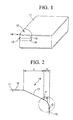
- a tip body 11 is formed of hard material such as a hard metal and is provided in the form of a rectangular plate.
- One rectangular surface (major surface) of the plate forms a rake face 12 and a peripheral surface thereof a flank face 13, and a crossing ridge between the rake face 12 and the flank face 13 constitutes a cutting-edge-forming ridge 14.
- a cutting edge tip which consists of a hard sintered body 15 such as a sintered hard alloy and a CBN sintered body 16 that are integrally sintered in layers, with the CBN sintered body 16 located on the side of the rake face 12.
- the above cutting-edge-forming ridge 14 is formed on the CBN sintered body 16.
- a plane chamfered surface 17 is formed in a crossing direction with the rake face 12 and the flank face 13 at an obtuse angle. Furthermore, as shown enlarged in Fig. 3, a phantom radius surface 18 is formed at the crossing ridge between the chamfered surface 17 and the flank face 13, which radius surface 18 is constituted, as in the section perpendicular to the cutting-edge-forming ridge 14, by a plurality of lines connected to one another to provide a generally convex shape. Especially in the present embodiment, the phantom radius surface 18 consists of plural (four) straight lines continuous to one another in a generally convex, bent-back manner.
- the phantom radius surface 18 is constituted by the same number of plane faces 19 as that of the above straight lines, which extend along the cutting-edge-forming ridge 14 between the chamfered surface 17 and the flank face 13, and which cross one another at an obtuse angle to extend in a convex, continuous manner from the chamfered surface 17 to the flank face 13.
- the widths of the plane faces 19 in the direction along the above straight lines are equal to one another, and neighboring plane faces 19 ... cross each other at equal angles.
- the radius of this arc that is, the phantom radius R of the phantom radius surface 18 in section is in the range from 0.02 to 0.07 mm.
- the surface-roughness of the rake face 12 is in the range of Rmax 0.01 to 2.0 ⁇ m in the maximum height defined in JIS B 0601, and the surface-roughness of the flank face 13 is in the range of Rmax 0.1 to 5.0 ⁇ m at least within the region of 100 ⁇ m from the intersection point Q as in the above-referenced section, that is, from the crossing ridge between the flank face 13 and the phantom radius surface 18.
- the surface-roughness of the rake face 12 is set to be 1/2 or less of the surface-roughness of the flank face 13 within that region of 100 ⁇ m from the crossing ridge between the flank face 13 and the phantom radius surface 18.
- the tip strength at that crossing ridge may be improved, leading to toughness of the cutting-edge-forming ridge 14 and to the fact that, if the cutting-edge-forming ridge 14 is formed by the CBN sintered body 16, the occurrence of chipping, breaking and the like may be prevented.
- the phantom radius surface 18 is constituted in section by a plurality of lines connected to one another to provide a generally convex shape, especially in the present embodiment because the chamfered surface 17 as well as the plane faces 19 that constitute the phantom radius surface 18 are all planar, its formation does not require such a high processing technique, leading to a reduction in the processing cost.
- each plane face 19 between neighboring intersection points O, P, and Q is located retracted from the circle of the phantom radius R, thereby lessening the contact with a workpiece and improving the wear resistance. If hardened steel or the like is cut, the occurrence of fins may be suppressed, leading to smooth working.
- the phantom radius surface 18 is constituted by four plane faces 19 ..., or as in the above-referenced section, the number of the straight lines that forms the phantom radius surface 18 is four. If this, for example, is two, that is, if the phantom radius surface 18 is constituted by two straight lines bent back only at one point O between the intersection points P and Q, the crossing angle of these two plane faces 19 at the point O becomes large, making it impossible to reliably prevent chipping and the like.
- the number of such straight lines as in the above-referenced section is preferred to be three or more.
- the number of the straight lines is preferred to be from 3 to 10.
- the phantom radius R in section of the arc derived from the generally bent-back straight lines constituting the phantom radius surface 18, is in the range of from 0.2 to 0.07 mm. If the phantom radius R is less than the above, the phantom radius surface 18 itself, although dependent on the tip body 11 and the honing width, becomes acute, possibly causing chipping and the like. On the contrary, if the phantom radius R exceeds the above range, the phantom radius surface 18 comes close to a plane surface, making the crossing ridge between the chamfered surface 17 and the flank face 13 susceptible to chipping and the like. Therefore, it is preferred that the phantom radius R be in the range of from 0.02 to 0.07 mm as in the present embodiment.
- the intersection points O, P, and Q lie in one arc. It is to be noted, however, that if crossing angles of neighboring plane faces 19 and their widths (lengths of the above straight lines) are not equal, and thus the intersection points O, P and Q do not lie in one arc, it is sufficient if the radius of an arc approximated to these intersection points falls within the above range.
- the plural, generally bent-back lines as in the above-referenced section, constituting the phantom radius surface 18 may in all or in part be curved, and may include a locally concave portion if provided as a whole in a convex form.
- the surface-roughness of the rake face 12 is set to be 1/2 or less of the surface-roughness of that portion of the flank face 13 on the side of the phantom radius surface 18. Due to this, a smooth flow of chips may be achieved that is produced by the cutting-edge-forming ridge 14 during cutting work, and which would otherwise possibly scratch the flank face 12, thereby preventing welding from taking place on the cutting-edge-forming ridge 14 and the flank face 12, and reducing the cutting force.
- the surface-roughness of the rake face 12 is set in the range of from Rmax 0.01 to 2.0 ⁇ m
- the surface-roughness of the flank face 13 is set in the range from Rmax 0.1 to 5.0 ⁇ m, thereby enabling achievement of the above effects more reliably, and thereby making it unnecessary to so carefully control the surface-roughness of the flank face 13 and simplifying the manufacturing process for throw-away tips.
- the throw-away tip at the lowermost in Table 1 with a phantom radius surface formed on the entire 0.1 mm honing width may be considered an embodiment of the present invention if that plane face closest to the rake face is taken as a chamfered surface.
- chipping and breaking may be prevented while reducing the processing cost, and an improvement in wear resistance may be made, with the result that the tip life is prolonged, and a high finishing accuracy is attained.
Claims (7)
- Plaquette de coupe amovible comprenant :un corps de plaquette comportant une face de dépouille et une face d'appui,une surface chanfreinée globalement plane, formée au niveau et le long d'une nervure formant une arête de coupe, où ladite face de dépouille et ladite face d'appui se croisent l'une l'autre, etune surface à rayon fictif formée au niveau d'une nervure de croisement entre ladite surface chanfreinée et ladite face d'appui, ladite surface à rayon fictif étant constituée, dans une coupe transversale perpendiculaire à ladite nervure formant une arrête de coupe, d'une pluralité de lignes reliées les unes aux autres pour fournir une forme globalement convexe.
- Plaquette de coupe amovible selon la revendication 1, dans laquelle un rayon d'un arc proche de ladite pluralité de lignes reliées suivant une forme globalement convexe, comme dans la section perpendiculaire à la nervure formant une arête de coupe, se situe dans la plage de 0,02 à 0,07 mm.
- Plaquette de coupe amovible selon la revendication 2, dans laquelle ladite surface à rayon fictif est constituée, dans la section perpendiculaire à la nervure formant une arête de coupe, d'une pluralité de droites rectilignes, dont certaines d'entre elles adjacentes se croisent les unes les autres de manière convexe.
- Plaquette de coupe amovible selon la revendication 3, dans laquelle le nombre desdites droites rectilignes, comme dans une section transversale perpendiculaire à la nervure formant une arête de coupe, constituant ladite surface à rayon fictif, est au moins de trois.
- Plaquette de coupe amovible selon la revendication 3 ou 4, dans laquelle un rayon d'un arc, comme dans la section perpendiculaire à la nervure formant une arête de coupe, qui s'étend au travers d'un point d'intersection entre ladite surface à rayon fictif et ladite surface chanfreinée, un point d'intersection entre ladite surface à rayon fantôme et ladite face d'appui, et des points de croisement parmi les droites adjacentes desdites droites rectilignes constituant ladite surface à rayon fictif, se situe dans une plage allant de 0,02 à 0,07 mm.
- Plaquette de coupe amovible selon la revendication 1, dans laquelle la rugosité en surface de ladite face de dépouille représente la moitié ou moins d'une rugosité en surface de ladite face d'appui dans une région de 100 µm depuis une nervure de croisement entre ladite face d'appui et ladite surface à rayon fictif.
- Plaquette de coupe amovible selon la revendication 1 ou 6, dans laquelle la rugosité en surface de ladite face d'appui se situe dans la plage de rugosité maximale Rmax allant de 0,01 à 2,0 µm, et la rugosité en surface de ladite face d'appui se situe dans la plage de rugosité maximale Rmax allant de 0,1 à 5,0 µm.
Applications Claiming Priority (4)
| Application Number | Priority Date | Filing Date | Title |
|---|---|---|---|
| JP2001028525 | 2001-02-05 | ||
| JP2001028525 | 2001-02-05 | ||
| JP2001184829A JP4228557B2 (ja) | 2001-02-05 | 2001-06-19 | スローアウェイチップ |
| JP2001184829 | 2001-06-19 |
Publications (2)
| Publication Number | Publication Date |
|---|---|
| EP1231004A1 EP1231004A1 (fr) | 2002-08-14 |
| EP1231004B1 true EP1231004B1 (fr) | 2006-04-26 |
Family
ID=26608935
Family Applications (1)
| Application Number | Title | Priority Date | Filing Date |
|---|---|---|---|
| EP02001949A Expired - Lifetime EP1231004B1 (fr) | 2001-02-05 | 2002-02-01 | Plaquette de coupe |
Country Status (6)
| Country | Link |
|---|---|
| US (1) | US6655881B2 (fr) |
| EP (1) | EP1231004B1 (fr) |
| JP (1) | JP4228557B2 (fr) |
| KR (1) | KR100824345B1 (fr) |
| CN (1) | CN1258421C (fr) |
| DE (1) | DE60210835T2 (fr) |
Families Citing this family (46)
| Publication number | Priority date | Publication date | Assignee | Title |
|---|---|---|---|---|
| JP2002192407A (ja) * | 2000-12-26 | 2002-07-10 | Ngk Spark Plug Co Ltd | 切削工具 |
| JPWO2002087812A1 (ja) * | 2001-04-27 | 2004-10-07 | Thk株式会社 | 長尺焼入れ鋼材の切削加工方法および切削加工装置 |
| US7234899B2 (en) * | 2003-05-19 | 2007-06-26 | Tdy Industries, Inc. | Cutting tool having a wiper nose corner |
| US7220083B2 (en) | 2003-10-15 | 2007-05-22 | Tdy Industries, Inc. | Cutting insert for high feed face milling |
| EP1714720B1 (fr) * | 2004-01-14 | 2011-05-18 | Sumitomo Electric Hardmetal Corp. | Plaquette de coupe |
| CN1950165B (zh) * | 2004-04-30 | 2011-11-16 | 住友电工硬质合金株式会社 | 表面被覆立方晶氮化硼烧结体工具 |
| US20050271483A1 (en) * | 2004-06-02 | 2005-12-08 | Sandvik Ab | Indexable cutting inserts and methods for producing the same |
| JP4585243B2 (ja) * | 2004-06-30 | 2010-11-24 | 株式会社アライドマテリアル | 超精密加工用単結晶ダイヤモンド切削工具 |
| JP4728961B2 (ja) * | 2004-07-29 | 2011-07-20 | 京セラ株式会社 | 切削工具 |
| SE529150C2 (sv) * | 2005-02-22 | 2007-05-15 | Seco Tools Ab | Skär för svarvning där fasvinkeln vid hörnet uppvisar ett minimum |
| SE529146C2 (sv) * | 2005-02-22 | 2007-05-15 | Seco Tools Ab | Skär för svarvning där fasvinkeln vid hörnet uppvisar ett minimum |
| SE528920C2 (sv) * | 2005-03-16 | 2007-03-13 | Sandvik Intellectual Property | Skär med keramisk skärspets där skärspetsen är mo nterad i en urtagning |
| CA2554824C (fr) * | 2005-03-16 | 2012-09-11 | Sumitomo Electric Hardmetal Corp. | Outil de coupe en cbn pour decoupage de haute qualite a rendement eleve |
| FR2883207B1 (fr) * | 2005-03-17 | 2008-10-03 | Essilor Int | Outil et machine pour operations d'usinage presentant un risque de travail a rebours |
| DE202006006081U1 (de) * | 2006-04-12 | 2007-08-16 | Kennametal Widia Produktions Gmbh & Co. Kg | Schneidenträger und Fräsmesserkopf |
| SE0602512L (sv) * | 2006-10-13 | 2008-04-22 | Seco Tools Ab | Negativt svarvskär med en fas mellan skäregg och släppningssida |
| SE530288C2 (sv) * | 2006-10-13 | 2008-04-22 | Seco Tools Ab | Negativt svarvskär med en fas mellan skäregg och släppningssida |
| US7905687B2 (en) * | 2007-01-16 | 2011-03-15 | Tdy Industries, Inc. | Cutting insert, tool holder, and related method |
| US7905689B2 (en) * | 2008-05-07 | 2011-03-15 | Tdy Industries, Inc. | Cutting tool system, cutting insert, and tool holder |
| US7976250B2 (en) | 2009-02-12 | 2011-07-12 | Tdy Industries, Inc. | Double-sided cutting inserts for high feed milling |
| US8491234B2 (en) | 2009-02-12 | 2013-07-23 | TDY Industries, LLC | Double-sided cutting inserts for high feed milling |
| US9586264B2 (en) | 2009-04-28 | 2017-03-07 | Kennametal Inc. | Double-sided cutting insert for drilling tool |
| GB0907737D0 (en) * | 2009-05-06 | 2009-06-10 | Element Six Ltd | An insert for a cutting tool |
| GB0908375D0 (en) | 2009-05-15 | 2009-06-24 | Element Six Ltd | A super-hard cutter element |
| US8807884B2 (en) | 2009-12-18 | 2014-08-19 | Kennametal Inc. | Tool holder for multiple differently-shaped cutting inserts |
| DE112011100215T5 (de) * | 2010-01-07 | 2015-10-01 | Gkn Sinter Metals, Llc. | Bearbeitungswerkzeug und Verfahren zu dessen HerstellUng |
| US20130022418A1 (en) * | 2010-02-24 | 2013-01-24 | Kyocera Corporation | Cutting tool |
| US9199312B2 (en) * | 2011-03-07 | 2015-12-01 | Kennametal Inc. | Cutting insert with discrete cutting tip and chip control structure |
| US9011049B2 (en) | 2012-09-25 | 2015-04-21 | Kennametal Inc. | Double-sided cutting inserts with anti-rotation features |
| US9283626B2 (en) | 2012-09-25 | 2016-03-15 | Kennametal Inc. | Double-sided cutting inserts with anti-rotation features |
| US10160083B2 (en) * | 2013-03-29 | 2018-12-25 | Sumitomo Electric Hardmetal Corp. | Method for manufacturing cubic boron nitride cutting tool and cubic boron nitride cutting tool |
| USD787578S1 (en) | 2014-01-22 | 2017-05-23 | Sumitomo Electric Hardmetal Corp. | Throw-away tip for metal cutting tool |
| US10195676B2 (en) * | 2014-08-27 | 2019-02-05 | Kyocera Corporation | Cutting insert, cutting tool, and method of manufacturing machined product |
| WO2016035490A1 (fr) * | 2014-09-05 | 2016-03-10 | 住友電工ハードメタル株式会社 | Pointe jetable |
| WO2016043127A1 (fr) * | 2014-09-16 | 2016-03-24 | 住友電気工業株式会社 | Plaquette de coupe et son procédé de fabrication |
| USD842909S1 (en) | 2015-10-29 | 2019-03-12 | Sumitomo Electric Sintered Alloy, Ltd. | Throw-away tip for cutting tool |
| USD848496S1 (en) * | 2016-09-28 | 2019-05-14 | Sumitomo Electric Hardmetal Corp. | Cutting tool |
| USD841704S1 (en) | 2016-09-29 | 2019-02-26 | Sumitomo Electric Sintered Alloy, Ltd. | Throw-away tip for cutting tool |
| JP6766998B2 (ja) * | 2016-12-15 | 2020-10-14 | 住友電工焼結合金株式会社 | スローアウェイチップ |
| EP3375550B1 (fr) * | 2016-12-26 | 2023-12-13 | Sumitomo Electric Hardmetal Corp. | Outil de coupe et son procédé de fabrication |
| WO2018155705A1 (fr) * | 2017-02-27 | 2018-08-30 | 京セラ株式会社 | Plaquette de coupe, outil de coupe et procédé de fabrication de pièce découpée |
| CN107598245B (zh) * | 2017-09-07 | 2019-03-29 | 中南大学 | 适用于高速切削精密加工镍基合金工件的铣刀 |
| USD909437S1 (en) * | 2018-02-16 | 2021-02-02 | Sumitomo Electric Hardmetal Corp. | Cutting tool |
| EP3834967A4 (fr) * | 2018-08-06 | 2022-05-04 | Sumitomo Electric Hardmetal Corp. | Outil de tournage |
| US11229957B2 (en) * | 2018-10-02 | 2022-01-25 | Jakob Lach Gmbh & Co. Kg | Method for producing a cutting tool for the machining of workpieces and cutting tool |
| CN112969546B (zh) * | 2018-10-29 | 2024-04-12 | 京瓷株式会社 | 切削刀片、切削刀具以及切削加工物的制造方法 |
Family Cites Families (12)
| Publication number | Priority date | Publication date | Assignee | Title |
|---|---|---|---|---|
| FR2509209A1 (fr) * | 1981-07-10 | 1983-01-14 | Feldmuehle Prod Tech France | Nouveau profil de plaquettes de coupe et autres materiels de coupe en ceramiques ou en cermets |
| DE3823199A1 (de) * | 1988-07-08 | 1990-01-11 | Feldmuehle Ag | Schneidplatte fuer spanabhebende bearbeitung |
| JP2867694B2 (ja) | 1990-11-27 | 1999-03-08 | 住友電気工業株式会社 | 多結晶ダイヤモンド切削工具およびその製造方法 |
| US5178645A (en) * | 1990-10-08 | 1993-01-12 | Sumitomo Electric Industries, Ltd. | Cutting tool of polycrystalline diamond and method of manufacturing the same |
| DE69117140T2 (de) * | 1990-11-22 | 1996-07-04 | Sumitomo Electric Industries | Polykristallines Dimantwerkzeug und Verfahren für seine Herstellung |
| CA2092932C (fr) | 1992-04-17 | 1996-12-31 | Katsuya Uchino | Element en carbone cemente revetu et methode de fabrication |
| SE501913C2 (sv) | 1993-10-21 | 1995-06-19 | Sandvik Ab | Skär för skärande verktyg |
| SE509224C2 (sv) * | 1994-05-19 | 1998-12-21 | Sandvik Ab | Vändskär |
| US6082936A (en) * | 1996-06-12 | 2000-07-04 | Sumitomo Electric Industries, Ltd. | Coated hard metal tool |
| SE512253C2 (sv) * | 1997-06-30 | 2000-02-21 | Sandvik Ab | Vändskär |
| SE516735C2 (sv) * | 1998-06-05 | 2002-02-26 | Sandvik Ab | Vändskär för kopiersvarvning |
| US6161990A (en) * | 1998-11-12 | 2000-12-19 | Kennametal Inc. | Cutting insert with improved flank surface roughness and method of making the same |
-
2001
- 2001-06-19 JP JP2001184829A patent/JP4228557B2/ja not_active Expired - Lifetime
-
2002
- 2002-01-31 US US10/059,241 patent/US6655881B2/en not_active Expired - Lifetime
- 2002-02-01 EP EP02001949A patent/EP1231004B1/fr not_active Expired - Lifetime
- 2002-02-01 DE DE60210835T patent/DE60210835T2/de not_active Expired - Lifetime
- 2002-02-05 KR KR1020020006576A patent/KR100824345B1/ko active IP Right Grant
- 2002-02-05 CN CNB021027943A patent/CN1258421C/zh not_active Expired - Lifetime
Also Published As
| Publication number | Publication date |
|---|---|
| US20020146292A1 (en) | 2002-10-10 |
| JP2002301605A (ja) | 2002-10-15 |
| KR100824345B1 (ko) | 2008-04-22 |
| DE60210835T2 (de) | 2006-11-30 |
| US6655881B2 (en) | 2003-12-02 |
| DE60210835D1 (de) | 2006-06-01 |
| EP1231004A1 (fr) | 2002-08-14 |
| KR20020065390A (ko) | 2002-08-13 |
| JP4228557B2 (ja) | 2009-02-25 |
| CN1382551A (zh) | 2002-12-04 |
| CN1258421C (zh) | 2006-06-07 |
Similar Documents
| Publication | Publication Date | Title |
|---|---|---|
| EP1231004B1 (fr) | Plaquette de coupe | |
| US5707185A (en) | Indexable insert for milling and milling cutter employing the same | |
| EP1850992B1 (fr) | Plaquette de coupe dotee d'un angle de chanfrein variable au niveau du tranchant de pointe | |
| JP4603550B2 (ja) | 高速送りの正面削り用切削インサート | |
| JP2882731B2 (ja) | のこ刃 | |
| US8523497B2 (en) | Cutting insert and indexable face mill | |
| US7878739B2 (en) | Cubic boron nitride radius end mill | |
| KR20180034575A (ko) | 절삭 인서트 및 날끝 교환식 회전 절삭 공구 | |
| JP4957000B2 (ja) | 切削工具 | |
| KR102327958B1 (ko) | 선삭 인서트 | |
| JP4784378B2 (ja) | 超高圧焼結体切削工具 | |
| EP0482512B1 (fr) | Fraise à tête sphérique | |
| US20220274184A1 (en) | Cutting insert | |
| KR960007687Y1 (ko) | 엔드밀 | |
| WO2006073233A1 (fr) | Plaquette d'outil de coupe | |
| CN114951720B (zh) | 切削刀片 | |
| JP4119967B2 (ja) | 刃先交換式回転工具 | |
| JP2007290057A (ja) | 超高圧焼結体切削工具 | |
| CN109570629B (zh) | 切削工具 | |
| JPH08318411A (ja) | 立方晶窒化硼素焼結体付きチップ | |
| JP4940864B2 (ja) | スローアウェイ式回転工具及びこれに装着されるチップ | |
| JPH0549408B2 (fr) | ||
| CN113396026B (zh) | 用于金属切削的车削刀片 | |
| JPH1058205A (ja) | スローアウェイチップ | |
| JPH0138601B2 (fr) |
Legal Events
| Date | Code | Title | Description |
|---|---|---|---|
| PUAI | Public reference made under article 153(3) epc to a published international application that has entered the european phase |
Free format text: ORIGINAL CODE: 0009012 |
|
| AK | Designated contracting states |
Kind code of ref document: A1 Designated state(s): AT BE CH CY DE DK ES FI FR GB GR IE IT LI LU MC NL PT SE TR |
|
| AX | Request for extension of the european patent |
Free format text: AL;LT;LV;MK;RO;SI |
|
| 17P | Request for examination filed |
Effective date: 20021129 |
|
| AKX | Designation fees paid |
Designated state(s): DE FR GB IT |
|
| GRAP | Despatch of communication of intention to grant a patent |
Free format text: ORIGINAL CODE: EPIDOSNIGR1 |
|
| GRAS | Grant fee paid |
Free format text: ORIGINAL CODE: EPIDOSNIGR3 |
|
| GRAA | (expected) grant |
Free format text: ORIGINAL CODE: 0009210 |
|
| AK | Designated contracting states |
Kind code of ref document: B1 Designated state(s): DE FR GB IT |
|
| PG25 | Lapsed in a contracting state [announced via postgrant information from national office to epo] |
Ref country code: IT Free format text: LAPSE BECAUSE OF FAILURE TO SUBMIT A TRANSLATION OF THE DESCRIPTION OR TO PAY THE FEE WITHIN THE PRESCRIBED TIME-LIMIT;WARNING: LAPSES OF ITALIAN PATENTS WITH EFFECTIVE DATE BEFORE 2007 MAY HAVE OCCURRED AT ANY TIME BEFORE 2007. THE CORRECT EFFECTIVE DATE MAY BE DIFFERENT FROM THE ONE RECORDED. Effective date: 20060426 |
|
| REG | Reference to a national code |
Ref country code: GB Ref legal event code: FG4D |
|
| REF | Corresponds to: |
Ref document number: 60210835 Country of ref document: DE Date of ref document: 20060601 Kind code of ref document: P |
|
| ET | Fr: translation filed | ||
| PLBE | No opposition filed within time limit |
Free format text: ORIGINAL CODE: 0009261 |
|
| STAA | Information on the status of an ep patent application or granted ep patent |
Free format text: STATUS: NO OPPOSITION FILED WITHIN TIME LIMIT |
|
| 26N | No opposition filed |
Effective date: 20070129 |
|
| REG | Reference to a national code |
Ref country code: FR Ref legal event code: PLFP Year of fee payment: 15 |
|
| REG | Reference to a national code |
Ref country code: FR Ref legal event code: PLFP Year of fee payment: 16 |
|
| REG | Reference to a national code |
Ref country code: FR Ref legal event code: PLFP Year of fee payment: 17 |
|
| PGFP | Annual fee paid to national office [announced via postgrant information from national office to epo] |
Ref country code: FR Payment date: 20210224 Year of fee payment: 20 Ref country code: IT Payment date: 20210222 Year of fee payment: 20 |
|
| PGFP | Annual fee paid to national office [announced via postgrant information from national office to epo] |
Ref country code: DE Payment date: 20210217 Year of fee payment: 20 Ref country code: GB Payment date: 20210219 Year of fee payment: 20 |
|
| REG | Reference to a national code |
Ref country code: DE Ref legal event code: R071 Ref document number: 60210835 Country of ref document: DE |
|
| REG | Reference to a national code |
Ref country code: GB Ref legal event code: PE20 Expiry date: 20220131 |
|
| PG25 | Lapsed in a contracting state [announced via postgrant information from national office to epo] |
Ref country code: GB Free format text: LAPSE BECAUSE OF EXPIRATION OF PROTECTION Effective date: 20220131 |