EP1229841B1 - System zum wundverschluss - Google Patents
System zum wundverschluss Download PDFInfo
- Publication number
- EP1229841B1 EP1229841B1 EP00980517A EP00980517A EP1229841B1 EP 1229841 B1 EP1229841 B1 EP 1229841B1 EP 00980517 A EP00980517 A EP 00980517A EP 00980517 A EP00980517 A EP 00980517A EP 1229841 B1 EP1229841 B1 EP 1229841B1
- Authority
- EP
- European Patent Office
- Prior art keywords
- tissue
- engaging section
- needle
- suturing apparatus
- suture
- Prior art date
- Legal status (The legal status is an assumption and is not a legal conclusion. Google has not performed a legal analysis and makes no representation as to the accuracy of the status listed.)
- Expired - Lifetime
Links
Images


Classifications
-
- A—HUMAN NECESSITIES
- A61—MEDICAL OR VETERINARY SCIENCE; HYGIENE
- A61B—DIAGNOSIS; SURGERY; IDENTIFICATION
- A61B17/00—Surgical instruments, devices or methods, e.g. tourniquets
- A61B17/0057—Implements for plugging an opening in the wall of a hollow or tubular organ, e.g. for sealing a vessel puncture or closing a cardiac septal defect
-
- A—HUMAN NECESSITIES
- A61—MEDICAL OR VETERINARY SCIENCE; HYGIENE
- A61B—DIAGNOSIS; SURGERY; IDENTIFICATION
- A61B17/00—Surgical instruments, devices or methods, e.g. tourniquets
- A61B17/04—Surgical instruments, devices or methods, e.g. tourniquets for suturing wounds; Holders or packages for needles or suture materials
- A61B17/0469—Suturing instruments for use in minimally invasive surgery, e.g. endoscopic surgery
-
- A—HUMAN NECESSITIES
- A61—MEDICAL OR VETERINARY SCIENCE; HYGIENE
- A61B—DIAGNOSIS; SURGERY; IDENTIFICATION
- A61B17/00—Surgical instruments, devices or methods, e.g. tourniquets
- A61B17/04—Surgical instruments, devices or methods, e.g. tourniquets for suturing wounds; Holders or packages for needles or suture materials
- A61B17/0482—Needle or suture guides
-
- A—HUMAN NECESSITIES
- A61—MEDICAL OR VETERINARY SCIENCE; HYGIENE
- A61B—DIAGNOSIS; SURGERY; IDENTIFICATION
- A61B17/00—Surgical instruments, devices or methods, e.g. tourniquets
- A61B17/04—Surgical instruments, devices or methods, e.g. tourniquets for suturing wounds; Holders or packages for needles or suture materials
- A61B17/0487—Suture clamps, clips or locks, e.g. for replacing suture knots; Instruments for applying or removing suture clamps, clips or locks
-
- A—HUMAN NECESSITIES
- A61—MEDICAL OR VETERINARY SCIENCE; HYGIENE
- A61B—DIAGNOSIS; SURGERY; IDENTIFICATION
- A61B17/00—Surgical instruments, devices or methods, e.g. tourniquets
- A61B17/04—Surgical instruments, devices or methods, e.g. tourniquets for suturing wounds; Holders or packages for needles or suture materials
- A61B17/06—Needles ; Sutures; Needle-suture combinations; Holders or packages for needles or suture materials
- A61B17/06004—Means for attaching suture to needle
-
- A—HUMAN NECESSITIES
- A61—MEDICAL OR VETERINARY SCIENCE; HYGIENE
- A61B—DIAGNOSIS; SURGERY; IDENTIFICATION
- A61B17/00—Surgical instruments, devices or methods, e.g. tourniquets
- A61B17/0057—Implements for plugging an opening in the wall of a hollow or tubular organ, e.g. for sealing a vessel puncture or closing a cardiac septal defect
- A61B2017/00637—Implements for plugging an opening in the wall of a hollow or tubular organ, e.g. for sealing a vessel puncture or closing a cardiac septal defect for sealing trocar wounds through abdominal wall
-
- A—HUMAN NECESSITIES
- A61—MEDICAL OR VETERINARY SCIENCE; HYGIENE
- A61B—DIAGNOSIS; SURGERY; IDENTIFICATION
- A61B17/00—Surgical instruments, devices or methods, e.g. tourniquets
- A61B17/0057—Implements for plugging an opening in the wall of a hollow or tubular organ, e.g. for sealing a vessel puncture or closing a cardiac septal defect
- A61B2017/00646—Type of implements
- A61B2017/00663—Type of implements the implement being a suture
-
- A—HUMAN NECESSITIES
- A61—MEDICAL OR VETERINARY SCIENCE; HYGIENE
- A61B—DIAGNOSIS; SURGERY; IDENTIFICATION
- A61B17/00—Surgical instruments, devices or methods, e.g. tourniquets
- A61B17/04—Surgical instruments, devices or methods, e.g. tourniquets for suturing wounds; Holders or packages for needles or suture materials
- A61B17/0401—Suture anchors, buttons or pledgets, i.e. means for attaching sutures to bone, cartilage or soft tissue; Instruments for applying or removing suture anchors
- A61B2017/0446—Means for attaching and blocking the suture in the suture anchor
- A61B2017/0454—Means for attaching and blocking the suture in the suture anchor the anchor being crimped or clamped on the suture
-
- A—HUMAN NECESSITIES
- A61—MEDICAL OR VETERINARY SCIENCE; HYGIENE
- A61B—DIAGNOSIS; SURGERY; IDENTIFICATION
- A61B17/00—Surgical instruments, devices or methods, e.g. tourniquets
- A61B17/04—Surgical instruments, devices or methods, e.g. tourniquets for suturing wounds; Holders or packages for needles or suture materials
- A61B17/0401—Suture anchors, buttons or pledgets, i.e. means for attaching sutures to bone, cartilage or soft tissue; Instruments for applying or removing suture anchors
- A61B2017/0464—Suture anchors, buttons or pledgets, i.e. means for attaching sutures to bone, cartilage or soft tissue; Instruments for applying or removing suture anchors for soft tissue
-
- A—HUMAN NECESSITIES
- A61—MEDICAL OR VETERINARY SCIENCE; HYGIENE
- A61B—DIAGNOSIS; SURGERY; IDENTIFICATION
- A61B17/00—Surgical instruments, devices or methods, e.g. tourniquets
- A61B17/04—Surgical instruments, devices or methods, e.g. tourniquets for suturing wounds; Holders or packages for needles or suture materials
- A61B17/0469—Suturing instruments for use in minimally invasive surgery, e.g. endoscopic surgery
- A61B2017/0472—Multiple-needled, e.g. double-needled, instruments
-
- A—HUMAN NECESSITIES
- A61—MEDICAL OR VETERINARY SCIENCE; HYGIENE
- A61B—DIAGNOSIS; SURGERY; IDENTIFICATION
- A61B17/00—Surgical instruments, devices or methods, e.g. tourniquets
- A61B17/04—Surgical instruments, devices or methods, e.g. tourniquets for suturing wounds; Holders or packages for needles or suture materials
- A61B17/0487—Suture clamps, clips or locks, e.g. for replacing suture knots; Instruments for applying or removing suture clamps, clips or locks
- A61B2017/0488—Instruments for applying suture clamps, clips or locks
-
- A—HUMAN NECESSITIES
- A61—MEDICAL OR VETERINARY SCIENCE; HYGIENE
- A61B—DIAGNOSIS; SURGERY; IDENTIFICATION
- A61B17/00—Surgical instruments, devices or methods, e.g. tourniquets
- A61B17/04—Surgical instruments, devices or methods, e.g. tourniquets for suturing wounds; Holders or packages for needles or suture materials
- A61B17/06—Needles ; Sutures; Needle-suture combinations; Holders or packages for needles or suture materials
- A61B2017/06057—Double-armed sutures, i.e. sutures having a needle attached to each end
Definitions
- the present invention relates to a system (apparatus) for wound closure, and in particular to a system for vascular wound closure utilizing a tissue suturing apparatus and a suture securing apparatus.
- the invention is suitable for applying at least one suture to close a wound, such as a puncture hole in a blood vessel, after an intravascular catheterization procedure.
- the invention is also suitable for applying a suture to a wound in other bodily tissue, such as the bowel.
- wound generally refers to herein to a hole, puncture, or any opening in tissue requiring closure.
- a catheter When performing catheterization procedures, such as angiography or angioplasty, a catheter is generally introduced percutaneously (i.e., through the skin) into the vascular system by first penetrating the skin and underlying tissue, and then the blood vessel with a sharpened hollow needle. Location of a blood vessel, such as an artery, is typically achieved by feeling for the pulse, since such structures usually cannot be seen through the skin. Next, a guide wire is commonly inserted through the lumen of the hollow needle and is caused to enter the selected blood vessel. Subsequently, the needle is typically slid off the guide wire and a combination of a dilator and sheath are fed over the guide wire and pushed through the skin to enter the vessel.
- the guide wire and dilator can then be removed and the desired catheter to carry out the procedure is fed through the lumen of the sheath and advanced through the vascular system until the working end of the catheter is appropriately positioned. Following the conclusion of the catheterization procedure, the working catheter will be withdrawn and, subsequently, the sheath can also be removed from the wound, or left in place to facilitate closure.
- a common method of sealing the wound is to maintain external pressure over the vessel until the puncture naturally seals. This method of puncture closure typically takes at least thirty minutes, with the length of time usually being substantially greater if the patient is hypertensive or anti-coagulated. In some anti-coagulated patients, the sheath is left in place for hours to allow the anti-coagulant to wear off. When human hand pressure is utilized, it can be uncomfortable for the patient and can use costly professional time on the part of the hospital staff. Other pressure techniques, such as pressure bandages, sandbags or clamps, have been employed, but these devices also require the patient to remain motionless for an extended period of time and the patient must be closely monitored to ensure their effectiveness.
- Surgical clips and clip appliers have also been used in vascular surgery, particularly to join severed vessels.
- U.S. Patent No. 4,929,240 describes clips generally arcuate in shape, which have two legs that are biased towards each other by clip applier jaws to capture vessel tissue therebetween.
- vascular clips have been successfully used in surgery, the surgical procedures in which the clips are typically used allow the surgeon to view the area to be clipped. In catheter puncture repair procedures, however, the wound is generally not visible, making proper clip application, if attempted, difficult.
- the instrument is activated to expose the needles.
- proximal movement of the instrument causes the needles to pass through the wound edge (from the inside to the outside) on either side of the puncture and the needles are withdrawn.
- a strand of suture material secured between the blunt ends of the needles is also drawn through the needle puncture holes, thereby leaving a span of suture across the hole on the inside of the vessel.
- the suture can then be tied to close the puncture.
- a disadvantage to this approach is the potential for needles to deflect in undesirable directions, and the potential difficultly of retrieving the needle tips. Also, the instruments used in this approach are relatively complex, may be unreliable in small sizes, and are costly to manufacture. A similar instrument is also described in U.S. Patent No. 5,417,699 .
- FIG. 1 Another suturing instrument is described in U.S. Patent No. 5,431,666 having a pair of longitudinally movable needles to pick up corresponding ends of suture at a distal end of the instrument.
- a needle capture mechanism provides two needle receiving portions, called ferrules, having a strand of suture material disposed therebetween, which are initially separated from the needles by a single gap in the instrument.
- tissue to be sutured is disposed in the gap between the needles and the two needle receiving portions called ferrules.
- a first needle punctures the tissue, engages one end of the suture, and draws it back through the tissue.
- the instrument can then be relocated to another portion of tissue and the second needle is actuated to pick up and draw the second end of the suture through the tissue.
- the suture material can then be tied or otherwise cinched in place to secure the tissue closed. In using this instrument, the surgeon is typically able to view the surgical site.
- U.S. Patent No. 5,766,183 describes a suture instrument for vascular wound closure in which the user does not need to view the wound.
- the suture instrument has a pair of longitudinally movable needles to pick up corresponding suture ends at a distal end of the instrument.
- the strand of suture material can have ferrules at each end.
- the instrument is placed through a sheath immediately above the vascular wound, or through a tissue tract larger than the vascular wound.
- One side of the tissue near the wound is punctured by a first needle which engages a ferrule and drawn back through the tissue with the ferrule.
- the instrument is then rotated to puncture the vascular tissue near another side of the wound with a second needle, which engages the other ferrule and drawn back through the tissue with the other ferrule.
- the instrument is withdrawn leaving the suture behind.
- Another instrument crimps a sleeve member over the free ends of the suture near the wound and cuts the suture such that the wound is secured closed.
- the suture instrument of the U.S. Patent No. 5,766,183 is that since the user does not directly view the site of the vascular wound to be closed, it can be difficult for the user after the first needle punctures the tissue to rotate the instrument such that the second needle is properly aligned at a location which will provide a suture capable of maintaining the wound closed.
- the second needle when applied to the tissue is approximately 180 degrees opposite the location where the first needle punctured the tissue, in respect to the puncture wound along a direction longitudinal with the blood vessel. If the suture is not properly placed across the wound, the suture may not completely close the wound.
- Another potential problem with this approach is the need for the tissue tract to be larger than the vascular wound.
- the system embodying the invention includes a first apparatus for applying a suture capable of closing the wound and a second apparatus for securing a sleeve member over the suture to secure the wound closed.
- the first apparatus includes a housing, a shaft having first and second ends in which the first end is coupled to the housing, a tissue engaging section coupled to the second end of the shaft, and first and second needles which extend from the housing through the interior of the shaft into the tissue engaging section, although the needles could be shorter and their movement through the shaft could be assisted by an additional driving mechanism.
- the shaft and tissue engaging section may be directed to the wound through a sheath (or cannula) previously inserted in the body of the patient.
- the tissue engaging section has first and second gaps disposed opposite each other.
- the first needle is extendable into the first gap through an opening of the tissue engaging section into a needle capturing portion coupled to one of the ends of a suture material, and is retractable with the captured end of the suture material.
- the second needle is extendable into the second gap through another opening of the tissue engaging section into another needle capturing portion coupled to the other end of the suture material, and is retractable with the captured end of the suture material.
- a suture tube in the housing extends through the housing and the shaft to the tissue engaging section, and is loaded with loop of suture material having two ends that extend to the needle capturing portions in the tissue engaging section.
- a selecting mechanism enables automatic or manual selection of each one of the first and second needles.
- a user operates an actuator member in the housing to drive and retract the selected needle to locate each end of the suture through the tissue about the wound.
- the suture material is left across the wound and the ends of the suture material extend from the sheath.
- the second apparatus secures a sleeve member over the two ends of the suture material to maintain the wound closed and then cuts the suture material exiting the secured sleeve member.
- the first apparatus may further include a tubule flexible guide section coupled to the tissue engaging section to guide the tissue engaging section through the sheath and wound into the blood vessel over a guide wire previously situated therein, and enable the guide wire to be removed.
- the shaft of the first apparatus may be circular, or oval in cross-section having a major axis of the oval in a first dimension as its extends from the housing, and then oval in cross-section in a second dimension for at least a substantial portion of the shaft near the tissue engaging section to accommodate the two needles being substantially parallel in a first plane near the housing and then substantially parallel in a second plane orthogonal to the first plane near the tissue engaging section.
- the oval shape of the shaft enables the needles to have a larger distance apart from each other than would otherwise be provided if the shaft were circular in cross-section.
- the sheath (or cannula) through which the suture instrument is located to access the wound is generally circular in cross-section and made of a flexible material, such that it can deform to accommodate the oval shaft of the suture instrument.
- the suture securing instrument of the system includes a tube extending from a housing to a distal end, and a rod extending through the tube in which the rod has first and second ends.
- the first end of the rod is coupled to a lever pivotally mounted in the housing to move the rod, while the second end of the rod extends into the chamber of the distal end.
- the distal end has a chamber into which the tube is received, a receptacle at its tip for receiving a round or oval tubular securing sleeve member, and an opening in chamber through which the two ends of suture material can extended after passing through the sleeve member.
- the second end of the rod is shaped to have an upper surface that is downwardly sloped to provide a step and then terminates at a hammer shaped section at the tip of the distal end.
- the hammer-shaped section may be adjacent a sleeve member loaded in the receptacle through a slot at the bottom of the receptacle.
- the user may pull the lever to retract the rod which enables the hammer-shaped section of the rod to be raised by a ramp located at the bottom of the chamber of the distal end, such that the pressure applied upon the sleeve member by the hammer-shaped section crimps at least part of the sleeve member.
- a knife is pivotally mounted in the chamber of the distal end, and, responsive to the hammer-shaped section of the rod abutting the knife as the rod is further retracted, rotates the knife upwards to cut the suture material extending from the crimped sleeve member.
- the suture securing instrument may then be withdrawn through the cannula leaving the crimped sleeve member to maintain the wound closure by the suture.
- the invention further includes a surgical kit including both the first and second apparatuses as parts of the kit.
- first apparatus allows a suture to be placed through a sheath and thus, there is no need to expand the diameter of the a puncture wound in order to place a suture across the wound, such as often needed in prior art suturing techniques.
- a further advantage of the first apparatus is the ability to locate the edges of the wound to be sutured from inside a blood vessel.
- FIGS. 1-10D an apparatus for applying a suture to body tissue is illustrated in FIGS. 1-10D and is designated generally by reference numeral 10.
- Another apparatus is also disclosed, designated by reference numeral 100 and illustrated in FIGS. 11-16F , for applying a connecting sleeve around the suture after it has been applied to the body tissue by apparatus 10 in order to secure the suture.
- first and second as used herein are for the reader's convenience and should not be interpreted as necessarily denoting the order in which the components are actuated.
- the system for wound closure of the present invention encompasses the combination of apparatuses 10 and 100.
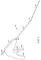
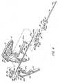
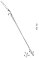
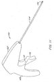
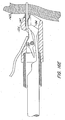
- apparatus 10 having a housing 12, a tissue engaging section 16, a shaft 14 extending from an opening 13 in the housing to the tissue engaging section 16, and a flexible guide tube 18 coupled to the tissue engaging section 16.
- the housing 12 has a body shaped like a pistol having a handle portion 12a, and may be made of a two-piece construction of molded plastic.
- the apparatus 10 includes a pair of needles 20 and 21, which extend from housing 12 through the shaft 14 into the tissue engaging section 16.
- Each needle 20 and 21 has a non-tissue engaging end in the housing having a spherical member 20a and 21 a, such as a ball or bearing, respectively, attached thereto.
- Both needles 20 and 21 and spherical members 20a and 21a may be a made of metal, such as surgical stainless steel.
- the spherical member 20a and 21a may have a bore into which the non-tissue engaging ends of the needles 20 and 21, respectively, extend and joined thereto, such as by welding.
- the apparatus 10 includes an actuator member 22 having two pins 22a extending into holes in the sides of housing 12 upon which the actuator member is pivotally mounted in the housing.
- Actuator member 22 has a portion which extends through an opening 12b in housing 12 to provide a trigger 23.
- a coil spring 24 is provided which hooks at one end in a notch 22b of actuator member 22 and is wound at the other end around a pin 26 located in holes in the sides of housing 12, such that the actuator member 22 is spring biased to retain trigger 23 normally in a forward position, as shown for example in FIG. 2 .
- the body of housing 12 has a front portion 15 providing a stop that limits the pivotal movement of the actuator member 22 to define the forward position of the trigger 23.
- a notch 22c is provided in the actuator member 22 which is shaped to received one of the non-engaging ends of needles 20 or 21, i.e., spherical members 20a or 21 a, to be driven forward by the actuator member 22 by a user pulling the trigger 23 portion of actuator member 22 towards handle portion 12a.
- Two grooves 22d are provided by three fingers 22e into which the needle 20 or 21 near the spherical members 20a or 21 a, respectively, may lie.
- a retainer member 28 is fixed in housing 12 by two flanges 28a above actuator member 22. As best shown in FIG. 4A , the retainer member 28 has a chamber 28b having a lower opening 28c and two grooves 28d formed by fingers 28e which allow the spherical members 20a or 2 1 a of needles 20 or 21, respectively, to be received in chamber 28b to restrict movement of the needle when held therein.
- the lower surface 28f of retainer member 28 is curved and faces correspondingly curved upper surface 22f of actuator member 22, such that the actuator member 22 is slidable along lower surface 28f responsive to a user pulling and releasing trigger 23.
- apparatus 10 has a needle selection mechanism having a selector lever (or arm) 34 which is rotationally coupled with a cam member 30.
- the cam member 30 and selector lever 34 is supported by an adapter 32 in housing 12.
- Adapter 32 is mounted in housing 12 by two flanges 32a.
- the selector lever 34 is pivotally mounted by a pin 32c extending upwards from adapter 32 at a hole 34a through the lever.
- Selector lever 34 extends through an opening 12c in housing 12 and has a downwardly protruding member 34b which is received in a notch 30c of cam member 30 to rotate cam member 30 in a pocket 32b in the adapter 32 as the selector lever is moved left or right.
- the cam member 30 has a tapered surface 30c to facilitate its rotation in pocket 32b and two tapered apertures 30a and 30b through which needles 20 and 21 respectively extend, as best shown in FIGS 4B and 4C .
- the selector 34 is moved left which rotates the cam member 30 to position needle 20 down and needle 21 up, such that end 20a is located in notch 20c and end 21a is located in retainer member 28 ( FIG. 5 ).
- the selector 34 is moved right which rotates the cam member 30 to position needle 20 up and needle 21 down, such that end 21a is located in notch 20c and end 20a is located in retainer member 28 ( FIGS. 6 and 7A).
- FIG. 7B shows the forward movement of actuator member 22 to drive needle 21 as needle 20 is retained in the needle retainer member 28.
- the needle selector 34 may further have another downwardly protruding member 34c which rides in a slot 28g on the upper surface of retainer member 28.
- the slot 28g is contoured to have angled lower regions on either side of a raised region into which member 34c can be located to releasably lock the position of lever 34 left or right.
- the adapter 32 has a bore extending therethrough in which a needle spreader 36 is located. Needle spreader has two channels into which needles 20 and 21 are respectively located to increase the distance between the needles 20 and 21 as they extend toward cam member 30, such that the needles are properly aligned to apertures 30a and 30b in the cam member.
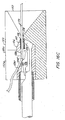
- the shaft 14 is mounted to housing 12 by a shaft mount 38 which is D-shaped at one end to register into a corresponding shaped opening in the adapter 32, an extending member 40 into which the shaft 14 is received, and a threaded nut 42 having an opening which extends over the shaft 14, extending member 40 and shaft mount 38, and screws onto the end of the adapter 32 to secure the shaft 14 to housing 12.
- Shaft 14 may be made of extruded plastic, or other substantially rigid material.
- Extending member 40 has a tapered annular portion 40a and a gap 40b onto which a sheath 159 (such as shown in FIG.
- sheath 17A can be inserted to releasably attach the sheath to apparatus 10 when the shaft 14, tissue engaging section 16, and guide section 18 is passed through the sheath.
- a sheath may be part of a percutaneous catheter introducer set sold by C.R. Bard Ireland Limited of Galway, Ireland.
- Sheath 159 has a head 159a having an opening capable of receiving the extending member 40, such when the extending member is inserted into the sheath, a gasket within the opening of head 159a registers into gap 40b and held in place by tapered annual portion 40a.
- the apparatus 10 may be released from sheath 159 by pulling the sheath away from housing 12.
- the tapered annular portion 40a may be made of a rigid material capable of sufficient elasticity to pass through the gasket in the sheath 159, and is shaped and sized in accordance with the opening of head 159a.
- the housing may also be releasably attached to a catheter.
- Apparatus 10 has a suture tube 44 which extends through an opening 12d in the handle portion 12a of housing 12, through notches 17 ( FIG. 4 ) along the interior of the left side of housing 12, a groove 36a in needle spreader 36 ( FIG. 4 ), and through shaft 14 to tissue engaging section 16.
- the suture material 62 extends in a loop through the tube 44 in which the two ends of the suture material are located in the tissue engaging section 16.
- the suture material may represent monofilament suture material or braided suture material.
- the suture tube 44 may have an optional extension member 43 coupled to the end 44a of the suture tube, as shown in FIG. 2A .
- the extension member 43 has a splitter 43a which forks to split tube 44 into two tubes 43b and 43c. Each of the tubes 43b and 43c may then be coupled to a separate compartment provided by hollow transparent member 43d and 43e, respectively.
- the suture material has a midpoint 63 between its two ends in splitter 43a, the loop 62 is divided into two loops 62a and 62b drawn through each of transparent members 43d and 43e through tubes 43b and 43c, respectively.
- loop 62a is closer to one of the ends of the suture material
- loop 62b is closer to the other end of the suture material.
- the transparent members 43d and 43e are optional, but can be used to protect each loop of suture material therein.
- the end of each transparent member 43d and 43e may be open or closed.
- the extension member 43 provides the user of apparatus 10 with a status indicator for the deployment of the suture. In other words, the user can visualize the suture material associated with loop 62a or 62b, respectively, when each end of the suture material is drawn up through suture tube 44 as each needle 20 and 21, respectively, places one end of the suture material through tissue.
- FIGS. 7C-7E Another embodiment of the selection mechanism is shown in FIGS. 7C-7E in which the selection mechanism automatically positions selector lever 34 to select needle 21 as needle 20 is driven forward by actuator member 22, rather than the manual positioning of selector lever 34 described earlier.
- the selection mechanism includes a ramp 35 coupled to actuator 22 which is sloped along surface 35a.
- the selection mechanism further includes a downwardly extending member 35b from selector lever 34 having a sloped surface 35c, such that when the actuator member 22 with ramp 35 rotates forward (in the direction of arrow 19a of bi-directional arrow 19), surface 35c of extending member 35b abuts and slides along surface 35a of ramp 35 to push the selector lever 34 from the left to the right (in the direction indicated by arrow 19b).
- FIGS. 7E-7F show the position of the selector lever 34 after the selector lever is automatically moved.
- the selector lever 34 need not extend through opening 12c of housing 12. In this manner, the selector lever 34 is initially positioned to the left when apparatus 10 is assembled, such that that needle 20 is pre-selected for the user to be driven, and then while the user drives the needle 20 forward, the selector lever is automatically moved to the right to select needle 21. In response, cam member 30 rotates as described earlier.
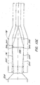
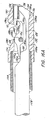
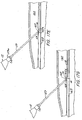
- the two needles 20 and 21 are substantially parallel in an x-z plane (parallel to the x axis 45) as they exit housing 12 into shaft 14 and then cross within the shaft to be substantially parallel in a y-z plane (parallel to the y axis 46) orthogonal to the x-z plane at the tissue engaging section 16.
- the shaft 14 is oval in cross-section having a major axis of the oval for at least a substantial portion of the shaft as it extends to shaft end 14b ( FIG. 4 ) near the tissue engaging section 16 in the y-z plane (parallel to the y-axis 46).
- the shaft 14 may be circular in cross-section (or oval in cross-section having a major axis along the plane parallel to the x-z plane), and then shaped to provide the desired oval cross-sectional shape as it extends near shaft end 14b.
- the shaft 14 may have an interior structure in which needles and suture tube extend in channels along the shaft from the housing to the tissue engagement section.
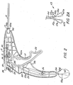
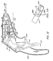
- the tissue engaging section 16 of the tissue suturing apparatus 10 is shown in more detail.
- the tissue engaging section 16 has a channel 48 for needle 20 to a first opening 50, a channel 52 for needle 21 to a second opening 54, and a channel 55 for suture tube 44 to a third opening 57.
- End 16a of the tissue engaging section 16 is received into shaft 14, such that edge 56 abuts the end of shaft 14.
- the tissue engaging section 16 has two holders or receptacles 58 and 60 which are each capable of holding a needle capturing portion 58a and 60a, respectively, received through openings 64 and 66, respectively.
- Needle capturing portions 58a and 60a are referred to herein as ferrules, such as described, for example, in U.S. Patent Nos. 5,431,666 and 5,766,183 , but may be any means by which a suture may be captured at the tip of a needle.
- the ferrules 58a and 60a each have an opening to an interior cavity shaped to enable the ferrule to frictionally engage the end of the needles 20 and 21, respectively, when received in the interior cavity.
- Each ferrule may be made of metal or plastic and may be oval in cross-section such that they can frictionally engage the tip of a needle.
- the ferrules 58a and 60a are each connected to one end of the two ends of a length of suture material or thread 62 extending through the suture tube 44 ( FIG. 2 ).
- Each ferrule holder 58 and 60 has a channel 58b and 60b, respectively, through which the suture material 62 from each ferrule 58a and 60a, respectively, extends.
- the tissue engaging section 16 has a first gap 68 and a second gap 70 in which the first gap 68 is along the lower side of section 16 and the second gap 70 is along the opposite upper side of section 16 and forward with respect to the first gap along the length of the section 16 in a direction distal from housing 12.
- the first gap 68 has two opposing surfaces 71 and 72 into which one side of a wound can be received, where opening 50 is located along surface 71 and opening 64 to ferrule holder 58 is located along surface 72 facing opening 50.
- the second gap 70 has two opposing surfaces 74 and 76 into which the other side of the wound can be received, where opening 54 is located along surface 74 and the opening 66 to ferrule holder 60 is located along surface 76 and faces opening 54.
- Each gap 68 and 70 is shaped to have a depth to facilitate the placement of the edge of a wound therein.
- Surface 72 which is the distal face of the first gap 68
- surface 74 which is the proximal face of the second gap 70 both serve as stop surfaces for the tissue engaging section 16. Such stop surfaces 72, 74 assist in the placement of the tissue engaging section 16 relative to the wound as will be described further below.
- An opening 61 ( FIG. 9B ) extends through surfaces 72 and 74 of gaps 68 and 70, respectively, through which the suture material 62 from ferrule 60a passes through to opening 57 into the suture tube 44.
- the length of needle 21 is longer than needle 20, as shown in FIG.
- Ends 16a and 16b of the tissue engaging section are angled with respect to each other as shown in FIG. 9A to facilitate placement of end 16b with guide section 18 through a sheath (or cannula) and the puncture wound to maximize blood vessel engagement.
- the two ferrules 58a and 60a and suture material 62 may be located in apparatus 10 during manufacture.
- the ferrules may be loaded into their associated ferrule holders, and then a wire with a hook draws the suture through opening 57 in the tissue engagement section 16 through opening 44a of the suture tube in housing 12 ( FIG. 2 ) or tubes 43c and 43b of optional extension member 43 ( FIG. 2A ).
- the tissue engagement section 16 may be made of metal, such as stainless steel, or other rigid biocompatible material.
- the tissue engagement section may be made of two pieces of shaped metal having bores providing the desired openings, channels, and receptacles, joined together down the middle along section 9A-9A by welding or heat shrinking of heat shrinkable tubing connecting the two pieces.
- the components in the housing 12, such as the actuator member 22, selector lever 34, and needle retainer 28, may be made of molded plastic.
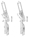
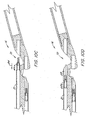
- FIGS. 9Cand 9D show the needle 20 being extended in the direction of arrow 78 into gap 68 to capture ferrule 58a upon tip 20b of the needle
- FIGS. 9E and 9F show needle 20 retracting with the captured ferrule 58a in the direction to arrow 80 into channel 48
- FIGS. 10A and 10B show the needle 21 being extended in the direction of arrow 82 into gap 70 to capture ferrule 60a upon tip 21b of the needle
- FIGS. 10C and 10D show needle 21 retracting with the captured ferrule 60a in the direction to arrow 84 into channel 52.
- Each of the needles 20 and 21 can be manually or automatically successively selected to extend and retract the selected needle with actuator member 22 to puncture through each side of a wound, as will be described later in connection with FIGS. 17A-17H .
- tip 196 in the figure is exemplary of each of tips 20b and 21b of needles 20 and 21, and ferrule 198 is exemplary of ferrules 58a and 60a.
- Tip 196 has a region 200 before its point 202 having a surface which tapers back towards the shaft 204 of the needle, such that when the tip 196 captures a ferrule, the ferrule's interior surface 205 engages at the interface 206 of point 202 with region 200.
- the diameter of the tip 196 along interface 206 is slightly larger than the interior width of ferrule 198 along its oval cross-section (indicated by arrow 210).
- the ferrule's interior width may be about 0.14 to 0.18 inches and the diameter of the tip along interface 207 may be about 0.002-0.004 inches larger than the ferrule's interior width. In this manner, the ferrule may be held better onto the tip when captured by the needle.
- the surface of region 200 may be parallel with the surface of shaft 204, as illustrated in needle tips 20b and 21b of FIGS. 9A , 9C-9F , and 10A-10D .
- a guide section 18 is attached to end 16b ( FIG. 9A ) of the tissue engaging section 16.
- the guide section 18 has a flexible tube 18a having a conical shaped end 18b with an opening through which a guide wire may be received, and a fixed ramp member 18c located under an opening 18d in the guide section, such that a guide wire may be extended through end 18b and directed by ramp member 18c through opening 18d.
- the tube 18a may be made of a biocompatible plastic, like heat shrink tubing, and the ramp may be made of plastic or metal which is attached or joined within tube 18a.
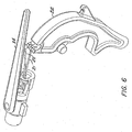
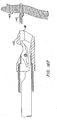
- the suture securing instrument 100 of the system is shown having a housing 102 similar to housing 12 of apparatus 10, a hollow tube 104 coupled to the housing 102 through an opening 103, and a distal end 106 coupled to tube 104.
- a rod 108 extends from housing 102 through tube 104 to the distal end 106.
- One end 108a of rod 108 is coupled to a lever 110 in housing 102.
- Lever 110 is pivotally mounted in housing 102 upon a pin 112 which extends through two holes 115 between upwardly extending flanges 113 of the lever. The ends of pin 112 fit into holes 114a of a pair of supporting members 114 located in the sides of housing 102.
- the lever 110 provides a trigger 116 extending through an opening 102b in housing 102.
- support members 114 may be moved, such that pin 112 extends into openings within the sides of housing 102 to enable lever 110 to pivot.
- the lever 110 and tube 104 may be made of plastic.
- the rod 108 has a spherical member or ball 109 attached at its end 108a via a hole in the ball.
- the ball 109 is mounted in a universal joint 118 provided by barrel-shaped member 120, adjuster shaft 122, and cover 124.
- Barrel-shaped member 120 extends through two holes 123 between flanges 113 of lever 110.
- the barrel-shaped member 120 is joined to one end 122a of an adjuster shaft 122 via a hole 120a extending through the barrel-shaped member.
- the other end of the adjuster shaft 122 has a socket 122b into which ball 109 is disposed.
- the cover 124 is a cylindrical member having an interior shaped to receive the ball 109 and socket 122b at an opening in one end, and a hole in the other end through which the rod 108 extends from ball 109.
- Cover 124 holds ball 109 of rod 108 in socket 122b, but allows the ball to be movable therein.
- ball 109 and socket 122b enables the rod 108 to rotate with respect to housing 102, while the barrel-shaped member 120 is rotatable in lever 110 to move the rod linearly within the slot 123a defined by flanges 113 as the housing 102 is tilted upwards or downwards.
- the lever 110 may be solid between flanges 113 and a slot provided for therein to enable the rod 108 to move linearly while barrel-shaped member 120 is rotated.
- the rod 108 extends from the universal joint 118 to tube 104 through an adapter 126, which may be similar to adapter 32 of apparatus 10.
- Tube 104 is mounted in an assembly 125 using components similar to components 36-42 in apparatus 10.
- the rod 108 may be composed of a rigid wire, such as piano wire, which is sufficiently flexible to bend in adapter 126 to the universal joint 118.
- the universal joint 118 may be removed, such that ball 119 of rod 108 is captured in a socket within barrel member 120.
- the distal end 106 has an interior chamber 128 into which end 108b of rod 108 is received and in linearly movable therein by a user moving trigger 116 towards handle portion 102a in the direction of arrow 127. In this manner, the end 108b of rod 108 can be retracted through the interior chamber 128 of distal end 106.
- End 108b of rod 108 is shaped to have a contoured upper surface 130, such as by cutting the wire by Electron Discharge Machining, or other similar wire shaping method.
- the upper surface 130 of end 108b, in the direction toward the tip 106a of the distal end 106, is first downwardly sloped towards tip 106a to provide a step or ledge 130a.
- the upper surface 130 is then further downwardly sloped after step 130a to provide a flat region 130b which is substantially parallel with the lower surface 132 of the end 108b of rod 108, and then upper surface 130 is upwardly sloped to terminate end 108b in a hammer shaped section 134.
- the lower surface 132 of end 108b of rod 108 is slightly downwardly sloped to form a wedge 134a along the hammer-shaped section 134.
- Tip 106a of distal end 106 and the lower interior surface 128d of chamber 128 is shaped to receive the hammer-shaped section 134, such as shown in FIG. 16A , in which a ramp 136 faces the wedge 134a of the hammer-shaped section 134.
- a compartment or receptacle 137 is located at tip 106a having an opening 138 through which a securing sleeve member 140 may be loaded until a stop 141 provided by a ledge in the compartment.
- Sleeve member 140 held in place by hammer-shaped section 134, which extends upwards through a slot 135 along the length of compartment 136.
- the securing sleeve member 140 may be a Ti-Knot titanium tube manufactured by LaserSurge, Inc. of Rochester, N.Y.
- Another slot 142 extends from the opening 138 through tip 106a to enable the hammer-shaped section 134 to pass there through when a sleeve member 140 is loaded into compartment 136, such as shown in FIG. 16B .
- FIG. 16B In FIG.
- the sleeve member is loaded in the direction of arrow 143 by pushing forwards trigger 116 until hammer-shaped section 134 extends through slot 142.
- An opening 128b is provided in the top 128a of the chamber 128, such that two ends of suture material can be received through the securing sleeve member 140, when a sleeve member is loaded in compartment 136, and passed through opening 128b.
- the sleeve member 140 in apparatus 100 may be loaded during manufacture or by the user.
- the sleeve member 140 is preferably oval in cross-section as shown in FIG. 15A , such that it is pre-deformed to facilitate the crimping of the sleeve member described below.
- the two ends of suture material 156 are shown, for example, passing through the interior 140a of the sleeve member.
- a knife 144 is pivotally mounted on a pin 146 in chamber 128.
- the pin 146 extends through two holes 148 on the sides of chamber 128.
- Knife 144 has a back portion 144a, a front portion 144b, and a U-shaped opening 144c therebetween through which pin 146 extends.
- Front portion 144b has an upper cutting surface 144d and a lower surface 144e.
- the back portion 144a of the knife may lie on step 130a to prevent the front portion 144b from rotating upwards until the cutting of suture material extending through sleeve member 140 is needed.
- the end 144b of the knife 144 has a ramped surface 144f to facilitate the passing of the suture material out through opening 128b.
- the top 128a may also have a ramped surface 128c to further facilitate the passing of the suture material out through opening 128b.
- an optional attachment 150 maybe located over distal end 106 having a funnel 152 with an aperture 154 in communication with sleeve member 140 through opening 138 to assist a user in loading the ends of the suture material 156 through the sleeve member 140 and opening 128b.
- the attachment 150 has an opening 150a which is shaped to receive end 106, and a slot 150b extending through the top surface 150c along the length of the attachment into which the ends of the suture material may be threaded prior to being directed through sleeve member 140. The attachment 150 is removed after the suture ends of the suture material are extended through opening 128b and grasped by the user.
- a user Once loaded with a sleeve member 140 in compartment 136 and two ends of suture material from the wound are passed through the sleeve member to exit opening 128b, a user, such as a surgeon, operates apparatus 100 by directing the apparatus through a sheath (cannula or tissue tract) through a tissue opening to the wound in tissue 163 through which the suture has been applied, such as by apparatus 10.
- the user applies tension to the suture material and pulls trigger 116 to retract rod 108.
- the retraction of rod 108 applies tension to the rod and force to raise the hammer-shaped section 134 upon ramp 136 and apply crimping pressure to substantially compress and deform at least part of the sleeve member 140, as shown in FIG. 16D .
- Rod 108 pulls stepped surface 130a away from the knife 144 to release it for rotation.
- Continued retraction of the rod 108 enables part of the upper surface 130 along hammer-shaped section 134 to abut the lower surface 144e of the knife 144, which rotates the knife upwards, such that upper cutting surface 144d of the knife cuts the suture material exiting the sleeve member 140, as shown in FIG. 16E .
- the crimped sleeve member 140 then is released from compartment 136 of distal end 106.
- Apparatus 100 may be removed from the sheath (or cannula or tissue tract).
- the required tension pressure on the rod applied by the user, via the lever 110, to crimp the sleeve member is substantially less than the compression force which needs to be applied by a user using the instrument described in U.S. Patent No. 5,766,183 to crimp a sleeve member. Accordingly, apparatus 100 is easier to operate than the sleeve crimping instrument disclosed in this patent. The operation of apparatus 100 will be further described in connection with FIGS. 17K-17M .
- FIGS. 17A-17M the method of closing a wound with the system of the present invention is shown.
- the apparatuses 10 and 100 are each directed through a sheath or cannula, however, they may be also be directed through a tract of tissue to a wound without a sheath or cannula.
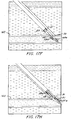
- FIG. 17A illustrates guide wire (or spring) 158 extending through a sheath 159 inserted percutaneously through skin 157 and tissue 160, and through puncture wound 162 in vessel 163.
- Vessel 163 may be a femoral artery, wherein puncture 162 was created to access for a catheter into the circulatory system of a patient to perform, for example, an angioplasty or angiography procedure.
- guide wire 158 is directed towards the torso of the patient.
- a catheter (not shown) is also inserted through the sheath 159 in the wound 162. The catheter is removed prior to use of tissue suturing apparatus 10.
- guide wire 158 is reinserted through the sheath left in the puncture wound at the end of the catherization procedure. If the selection mechanism is manual, the user verifies that needle 20 is selected, and if not, positions selector lever 34 of the selection mechanism to select needle 20.
- the tissue suturing apparatus 10 is threaded over the guide wire 158 by passing the guide wire 158 through opening 18d of the guide section 18 ( FIG. 17B ).
- the guide wire 159 is then removed by pulling the wire through opening 18b ( FIGS. 17B and 17C ).
- the guide section 18 of apparatus 10 reduces potential trauma to the inside of the vessel, enhance wound edge engagement and permits reinsertion of the guide wire if desired by the user.
- the tissue engaging section 16 is passed through the sheath 159 in the wound 162 into the blood vessel 163 until the extending member 40 ( FIG. 1 ) locks and connects apparatus 10 to the head 159a of the sheath ( FIG. 17D ), as described earlier.
- the tissue engaging section 16 is angled at its end 16b with respect to end 16a to facilitate engagement of the blood vessel wound.
- the needle section mechanism is manual, the user next selects needle 21 with selector lever 34.
- the wound is thus sutured from inside the blood vessel and no rotation of the apparatus 10 is needed to place the suture across the wound.
- the optional extension member 43 it illustrates the status of suture deployment through the tissue engagement sites on opposite sides of the wound. If this display indicates that only one suture end has been placed (i.e., only one of loop 62a or 62b ( FIG. 2A ) moved instead of both loops) then the apparatus 10 can be partially removed, the suture material cut and removed, the guide wire reintroduced through the guide section 18, and the closure procedure described above started again with another apparatus 10 loaded with suture material.
- the apparatus 10 is removed from the sheath 159 ( FIG. 17I ), and as the apparatus 10 is withdrawn, the two ends of the suture material are retained in the tissue engaging section by the ferrules captured on the needles 20 and 21, such that the suture material is drawn through the vascular tissue until a loop of suture material 164 extends across the wound 162 ( FIG. 17J ).
- the apparatus 10 may need to be rotated about 90 degrees to allow the tissue engaging section 16 to be removed from wound 162 and the blood vessel 163.
- the suture material 164 is then cut to release tissue engaging section 16 from the stand of suture now spanning both sides of the wound, such that the two cut ends of the suture material extend from sheath 159.
- the two ends of the suture material are next threaded, preferably through attachment 150, into the distal end of apparatus 100 having been loaded with a sleeve member 140, such as shown FIG. 16C .
- the tube 104 of apparatus 100 is then inserted into sheath 159 such that distal end 106 lies in proximity of the wound ( FIG. 17K ).
- the user pulls lever 110 to crimp the sleeve member 140 and then cut the suture, as described earlier in connection with FIG. 16D-16E .
- Apparatus 100 is then withdrawn from sheath 159.
- a small loop of suture 166 is now secured by a crimped sleeve 140a left behind to close wound 162 ( FIG. 17L ), as described earlier in connection with FIG. 16D .
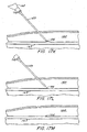
- the sheath 159 is then removed from the patient ( FIG. 17M ), and a topical bandage may be applied.
- Apparatuses 10 and 100 may be sizes to accommodate the cross-section of the sheath 159.
- the sheath is six French (2mm in diameter)
- the size of shaft 14 and tissue engaging section 16 of apparatus 10 and the size of tube 114 and distal end 106 of apparatus 100 may be sized to accommodate this diameter.
- the apparatus 10 can provide, for example, bite sizes between each tissue engagement site of the suture in vascular tissue 163 and the edge of the wound of about 3mm.
- apparatus 10 can be easily miniaturized to the desired application.
- the user can receive tactile feedback through apparatus 10 when opposing sides, representing the superior and inferior sides of the wound, are respectively received in gaps 68 and 70.
- apparatuses 10 and 100 are used in combination such as described above.
- each apparatus may also be used separately to suture a wound or seal a suture closed, respectively.
- apparatus 10 and 100 may be provided as part of a surgical kit 167 useful for closing a puncture wound in a blood vessel.
- the kit 167 preferably includes apparatus 10, apparatus 100, sheath 159 and a dialator assembly 172.
- the sheath 159 has tubing 159b to valves(s) 159c through which fluid may be inserted.
- the kit packaging has a base 168 molded to inset the parts of the kit, and a cover 170 over the base to seal such parts therein.
- the base 168 can be at least partially fabricated from thermoformed plastic 602 fabricated from polyethylene fibers, such as TYVEK available from Dupont, to facilitate sterilization.
Claims (20)
- Gewebenähapparat (10), umfassend:einen Gewebeeingriffsabschnitt (16) mit einem distalen und einem proximalen Ende,einen ersten Gewebeaufnahmespalt (68) innerhalb des Gewebeeingriffsabschnitts (16) und einen zweiten Gewebeaufnahmespalt (70) getrennt vom ersten Gewebeaufnahmespalt (68) innerhalb des Gewebeeingriffsabschnitts (16),wobei sich die ersten (68) und zweiten (70) Gewebeaufnahmespalte in verschiedenen Richtungen vom Gewebeeingriffsabschnitt (16) voneinander weg wenden, und wobei die ersten (68) und zweiten (70) Gewebeaufnahmespalte den Gewebeeingriffsabschnitt (16) entlang der Länge nach von einander versetzt sind,gekennzeichnet durchein proximale Seite des ersten Gewebeaufnahmespalts (68) und eine proximale Seite des zweiten Gewebeaufnahmespalts (70), die jeweils eine Öffnung (50, 54) umfassen, die zu einem Kanal (48, 52) für eine Nadel führt.
- Gewebenähapparat (10) nach Anspruch 1, wobei sich die ersten (68) und zweiten (70) Gewebeaufnahmespalte auf gegenüberliegenden Seiten des Gewebeeingriffsabschnitts (16) befinden.
- Gewebenähapparat (10) nach Anspruch 2, wobei sich die ersten (68) und zweiten (70) Gewebeaufnahmespalte auf gegenüberliegenden perimetrischen Seiten des Gewebeeingriffsabschnitts (16) befinden.
- Gewebenähapparat (10) nach Anspruch 1, ferner umfassend einen Schaft (14), der mit einem Griff (12a) verbunden ist, wobei der Schaft (14) am proximalen Ende des Gewebeeingriffsabschnitts (16) angebracht ist, und ein Führungsrohr (18), das am distalen Ende des Gewebeeingriffsabschnitts (16) angebracht ist.
- Gewebenähapparat (10) nach Anspruch 1, wobei das distale Ende des Gewebeeingriffsabschnitts (16) vom proximalen Ende des Gewebeeingriffsabschnitts (16) winkelig versetzt ist.
- Gewebenähapparat (10) nach Anspruch 1, wobei der erste Gewebeaufnahmespalt (68) näher zum proximalen Ende des Gewebeeingriffsabschnitts (16) als der zweite Gewebeaufnahmespalt (70) ist.
- Gewebenähapparat (10) nach Anspruch 1, wobei der erste Gewebeaufnahmespalt (68) eine erste Anschlagsfläche (72) umfasst, die sich auf einer distalen Seite des ersten Gewebeaufnahmespalts (68) befindet, und der zweite Gewebeaufnahmespalt (70) eine zweite Anschlagsfläche (74) umfasst, die sich auf einer proximalen Seite des zweiten Gewebeaufnahmespalts (70) befindet.
- Gewebenähapparat (10) nach Anspruch 7, wobei die erste Anschlagsfläche (72) um weniger als 15 Grad von einem senkrechten Querschnitt des Gewebeeingriffsabschnitts (16) benachbart zum distalen Ende abgewinkelt ist und wobei die zweite Anschlagsfläche (74) um weniger als 15 Grad von einem senkrechten Querschnitt des Gewebeeingriffsabschnitts (16) benachbart zum proximalen Ende abgewinkelt ist.
- Gewebenähapparat (10) nach Anspruch 1, wobei die Öffnung (50) auf der proximalen Seite des ersten Gewebeaufnahmespalts (68) näher zum proximalen Ende des Gewebeeingriffsabschnitts (16) als die Öffnung (54) auf der proximalen Seite des zweiten Gewebeaufnahmespalts (70) ist.
- Gewebenähapparat (10) nach Anspruch 1, wobei ein distale Seite des ersten Gewebeaufnahmespalts (68) und eine distale Seite des zweiten Gewebeaufnahmespalts (70) jeweils eine Öffnung (64, 66) umfassen, die zu einem Nahthalter (58, 60) führt.
- Gewebenähapparat (10) nach Anspruch 10, wobei Nahthalter (58) auch ein Ferrulenhalter ist.
- Gewebenähapparat (10) nach Anspruch 11, ferner umfassend einen zusätzlichen Kanal (58b, 60b) zum Halten von Nahtmaterial (62) benachbart zu jedem Ferrulenhalter (58, 60).
- Gewebenähapparat (10) nach Anspruch 1, ferner umfassend einen ersten Nadelkanal (48), einen zweiten Nadelkanal (52) und einen Kanal (55) für Nahtmaterial innerhalb des proximalen Endes des Gewebeeingriffsabschnitts (16).
- Gewebenähapparat (10) nach Anspruch 1, wobei der Gewebeeingriffsabschnitt (16) einen im Wesentlichen ovalen Querschnitt aufweist.
- Gewebenähapparat (10) nach Anspruch 1, wobei sich der erste Gewebeaufnahmespalt (68) eine Tiefe erstreckt, die größer als eine halbe Breite des Gewebeeingriffsabschnitts (16) ist, und wobei sich der zweite Gewebeaufnahmespalt (70) eine Tiefe erstreckt, die größer als die halbe Breite des Gewebeeingriffsabschnitts (16) ist.
- Gewebenähapparat (10) nach Anspruch 8, wobei ein Querschnitt am ersten Gewebeaufnahmespalt (68) außerdem einen Nadelkanal zum Halten einer Nadel umfasst, die so ausgelegt ist, dass sie durch den zweiten Gewebeaufnahmespalt (70) durchtritt.
- Gewebenähapparat (10) nach Anspruch 1, wobei ein Querschnitt am zweiten Gewebeaufnahmespalt (70) außerdem einen Ferrulenhalter zum Halten einer Ferrule umfasst, die so ausgelegt ist, dass sie durch eine Nadel (21), die durch den ersten Gewebeaufnahmespalt (68) durchtritt, erfasst wird.
- Gewebenähapparat (10) nach Anspruch 1, umfassend:einen ersten Ferrulenhalter (58) und einen zweiten Ferrulenhalter (60), wobei der Ferrulenhalter (58) näher zum proximalen Ende des Gewebeeingriffsabschnitts (16) als der zweite Ferrulenhalter (60) ist.
- Gewebenähapparat (10) nach Anspruch 18, wobei der ersten Ferrulenhalter (58) eine erste Öffnung (64) zur Aufnahme einer ersten Ferrule (58a) umfasst und der zweite Ferrulenhalter (60) eine zweite Öffnung (66) zur Aufnahme einer zweiten Ferrule (60a) umfasst, wobei die erste Öffnung (64) in einer Ebene im Wesentlichen senkrecht zu einer Längsachse liegt, die durch das distale Ende des Gewebeeingriffsabschnitts (16) verläuft, und wobei die zweite Öffnung (66) in einer Ebene schief zur Längsachse liegt, die durch das distale Ende des Gewebeeingriffsabschnitts (16) verläuft.
- Kit zum Nähen einer Wunde, wobei der Kit umfasst:einen Gewebenähapparat (10) nach Anspruch 1, wobei der Gewebenähapparat (10) ferner eine erste Nadel (20), eine erste Ferrule (58a) zum Halten eines ersten Endes von Nahtmaterial, eine zweite Nadel (21) und eine zweite Ferrule (60a) zum Halten eines zweiten Endes von Nahtmaterial; undein Nahtbefestigungsinstrument (100), das ein Hülsenelementfach (137), eine Stange (108) mit einem hammerförmigen Abschnitt (134) zum Quetschen eines Hülsenelements (140) und ein Messer (144) zum Abschneiden von Nahtmaterial umfasst.
Applications Claiming Priority (3)
| Application Number | Priority Date | Filing Date | Title |
|---|---|---|---|
| US16633899P | 1999-11-19 | 1999-11-19 | |
| US166338P | 1999-11-19 | ||
| PCT/US2000/031727 WO2001035833A1 (en) | 1999-11-19 | 2000-11-20 | System for wound closure |
Publications (3)
| Publication Number | Publication Date |
|---|---|
| EP1229841A1 EP1229841A1 (de) | 2002-08-14 |
| EP1229841A4 EP1229841A4 (de) | 2008-04-30 |
| EP1229841B1 true EP1229841B1 (de) | 2010-07-28 |
Family
ID=22602851
Family Applications (1)
| Application Number | Title | Priority Date | Filing Date |
|---|---|---|---|
| EP00980517A Expired - Lifetime EP1229841B1 (de) | 1999-11-19 | 2000-11-20 | System zum wundverschluss |
Country Status (11)
| Country | Link |
|---|---|
| US (2) | US6641592B1 (de) |
| EP (1) | EP1229841B1 (de) |
| JP (1) | JP4578043B2 (de) |
| KR (1) | KR100943999B1 (de) |
| AU (1) | AU1777001A (de) |
| BR (1) | BR0015763A (de) |
| DE (1) | DE60044748D1 (de) |
| ES (1) | ES2350030T3 (de) |
| IL (1) | IL149695A0 (de) |
| MX (1) | MXPA02005018A (de) |
| WO (1) | WO2001035833A1 (de) |
Cited By (13)
| Publication number | Priority date | Publication date | Assignee | Title |
|---|---|---|---|---|
| US8663249B2 (en) | 2010-04-29 | 2014-03-04 | Vinay Badhwar | Automatic suturing apparatus and methods of use |
| US8814025B2 (en) | 2011-09-15 | 2014-08-26 | Ethicon Endo-Surgery, Inc. | Fibrin pad matrix with suspended heat activated beads of adhesive |
| US8899464B2 (en) | 2011-10-03 | 2014-12-02 | Ethicon Endo-Surgery, Inc. | Attachment of surgical staple buttress to cartridge |
| US8985429B2 (en) | 2011-09-23 | 2015-03-24 | Ethicon Endo-Surgery, Inc. | Surgical stapling device with adjunct material application feature |
| US8998060B2 (en) | 2011-09-13 | 2015-04-07 | Ethicon Endo-Surgery, Inc. | Resistive heated surgical staple cartridge with phase change sealant |
| US8998059B2 (en) | 2011-08-01 | 2015-04-07 | Ethicon Endo-Surgery, Inc. | Adjunct therapy device having driver with cavity for hemostatic agent |
| US9089326B2 (en) | 2011-10-07 | 2015-07-28 | Ethicon Endo-Surgery, Inc. | Dual staple cartridge for surgical stapler |
| US9101359B2 (en) | 2011-09-13 | 2015-08-11 | Ethicon Endo-Surgery, Inc. | Surgical staple cartridge with self-dispensing staple buttress |
| US9125649B2 (en) | 2011-09-15 | 2015-09-08 | Ethicon Endo-Surgery, Inc. | Surgical instrument with filled staple |
| US9198644B2 (en) | 2011-09-22 | 2015-12-01 | Ethicon Endo-Surgery, Inc. | Anvil cartridge for surgical fastening device |
| US9254180B2 (en) | 2011-09-15 | 2016-02-09 | Ethicon Endo-Surgery, Inc. | Surgical instrument with staple reinforcement clip |
| US9393018B2 (en) | 2011-09-22 | 2016-07-19 | Ethicon Endo-Surgery, Inc. | Surgical staple assembly with hemostatic feature |
| US9492170B2 (en) | 2011-08-10 | 2016-11-15 | Ethicon Endo-Surgery, Inc. | Device for applying adjunct in endoscopic procedure |
Families Citing this family (301)
| Publication number | Priority date | Publication date | Assignee | Title |
|---|---|---|---|---|
| US8795332B2 (en) | 2002-09-30 | 2014-08-05 | Ethicon, Inc. | Barbed sutures |
| US6241747B1 (en) | 1993-05-03 | 2001-06-05 | Quill Medical, Inc. | Barbed Bodily tissue connector |
| US5766183A (en) * | 1996-10-21 | 1998-06-16 | Lasersurge, Inc. | Vascular hole closure |
| US5931855A (en) | 1997-05-21 | 1999-08-03 | Frank Hoffman | Surgical methods using one-way suture |
| FR2768324B1 (fr) | 1997-09-12 | 1999-12-10 | Jacques Seguin | Instrument chirurgical permettant, par voie percutanee, de fixer l'une a l'autre deux zones de tissu mou, normalement mutuellement distantes |
| US6045551A (en) | 1998-02-06 | 2000-04-04 | Bonutti; Peter M. | Bone suture |
| US6964668B2 (en) | 1999-03-04 | 2005-11-15 | Abbott Laboratories | Articulating suturing device and method |
| US7842048B2 (en) | 2006-08-18 | 2010-11-30 | Abbott Laboratories | Articulating suture device and method |
| US20040092964A1 (en) * | 1999-03-04 | 2004-05-13 | Modesitt D. Bruce | Articulating suturing device and method |
| US7235087B2 (en) | 1999-03-04 | 2007-06-26 | Abbott Park | Articulating suturing device and method |
| US8137364B2 (en) | 2003-09-11 | 2012-03-20 | Abbott Laboratories | Articulating suturing device and method |
| US7001400B1 (en) | 1999-03-04 | 2006-02-21 | Abbott Laboratories | Articulating suturing device and method |
| US7666204B2 (en) | 1999-04-09 | 2010-02-23 | Evalve, Inc. | Multi-catheter steerable guiding system and methods of use |
| US10327743B2 (en) | 1999-04-09 | 2019-06-25 | Evalve, Inc. | Device and methods for endoscopic annuloplasty |
| US7811296B2 (en) | 1999-04-09 | 2010-10-12 | Evalve, Inc. | Fixation devices for variation in engagement of tissue |
| US20040044350A1 (en) | 1999-04-09 | 2004-03-04 | Evalve, Inc. | Steerable access sheath and methods of use |
| ATE492219T1 (de) | 1999-04-09 | 2011-01-15 | Evalve Inc | Vorrichtung zur herzklappenoperation |
| US8216256B2 (en) | 1999-04-09 | 2012-07-10 | Evalve, Inc. | Detachment mechanism for implantable fixation devices |
| US6752813B2 (en) | 1999-04-09 | 2004-06-22 | Evalve, Inc. | Methods and devices for capturing and fixing leaflets in valve repair |
| US7744613B2 (en) | 1999-06-25 | 2010-06-29 | Usgi Medical, Inc. | Apparatus and methods for forming and securing gastrointestinal tissue folds |
| US7637905B2 (en) | 2003-01-15 | 2009-12-29 | Usgi Medical, Inc. | Endoluminal tool deployment system |
| US7416554B2 (en) | 2002-12-11 | 2008-08-26 | Usgi Medical Inc | Apparatus and methods for forming and securing gastrointestinal tissue folds |
| US7618426B2 (en) | 2002-12-11 | 2009-11-17 | Usgi Medical, Inc. | Apparatus and methods for forming gastrointestinal tissue approximations |
| US6447516B1 (en) | 1999-08-09 | 2002-09-10 | Peter M. Bonutti | Method of securing tissue |
| US6368343B1 (en) | 2000-03-13 | 2002-04-09 | Peter M. Bonutti | Method of using ultrasonic vibration to secure body tissue |
| US6635073B2 (en) | 2000-05-03 | 2003-10-21 | Peter M. Bonutti | Method of securing body tissue |
| US9138222B2 (en) | 2000-03-13 | 2015-09-22 | P Tech, Llc | Method and device for securing body tissue |
| US7094251B2 (en) | 2002-08-27 | 2006-08-22 | Marctec, Llc. | Apparatus and method for securing a suture |
| US7083628B2 (en) | 2002-09-03 | 2006-08-01 | Edwards Lifesciences Corporation | Single catheter mitral valve repair device and method for use |
| US7220266B2 (en) | 2000-05-19 | 2007-05-22 | C. R. Bard, Inc. | Tissue capturing and suturing device and method |
| SE0002878D0 (sv) | 2000-08-11 | 2000-08-11 | Kimblad Ola | Device and method for treatment of atrioventricular regurgitation |
| US8313496B2 (en) * | 2001-02-02 | 2012-11-20 | Lsi Solutions, Inc. | System for endoscopic suturing |
| US7056331B2 (en) | 2001-06-29 | 2006-06-06 | Quill Medical, Inc. | Suture method |
| US6848152B2 (en) | 2001-08-31 | 2005-02-01 | Quill Medical, Inc. | Method of forming barbs on a suture and apparatus for performing same |
| EP1450699A4 (de) * | 2001-10-22 | 2007-05-30 | Interventional Therapies Llc | Entfernbare hülse |
| US20030078601A1 (en) * | 2001-10-22 | 2003-04-24 | Oleg Shikhman | Crimping and cutting device |
| WO2003034924A1 (en) * | 2001-10-22 | 2003-05-01 | Interventional Therapies, L.L.C. | Wound suturing device |
| US20120053599A1 (en) * | 2001-10-22 | 2012-03-01 | Oleg Shikhman | Suturing, crimping and cutting device |
| US6575971B2 (en) | 2001-11-15 | 2003-06-10 | Quantum Cor, Inc. | Cardiac valve leaflet stapler device and methods thereof |
| US6719765B2 (en) | 2001-12-03 | 2004-04-13 | Bonutti 2003 Trust-A | Magnetic suturing system and method |
| US7048754B2 (en) | 2002-03-01 | 2006-05-23 | Evalve, Inc. | Suture fasteners and methods of use |
| EP1482841B1 (de) | 2002-03-14 | 2005-12-07 | Yeung, Jeffery E. | Nahtanker und adaptationsvorrichtung |
| US9155544B2 (en) | 2002-03-20 | 2015-10-13 | P Tech, Llc | Robotic systems and methods |
| US6773450B2 (en) | 2002-08-09 | 2004-08-10 | Quill Medical, Inc. | Suture anchor and method |
| US8100940B2 (en) | 2002-09-30 | 2012-01-24 | Quill Medical, Inc. | Barb configurations for barbed sutures |
| US20040088003A1 (en) | 2002-09-30 | 2004-05-06 | Leung Jeffrey C. | Barbed suture in combination with surgical needle |
| US20040102808A1 (en) * | 2002-11-26 | 2004-05-27 | Voss Laveille Kao | Needle for retrieving a suture |
| US7942884B2 (en) | 2002-12-11 | 2011-05-17 | Usgi Medical, Inc. | Methods for reduction of a gastric lumen |
| US7942898B2 (en) | 2002-12-11 | 2011-05-17 | Usgi Medical, Inc. | Delivery systems and methods for gastric reduction |
| US7160309B2 (en) | 2002-12-31 | 2007-01-09 | Laveille Kao Voss | Systems for anchoring a medical device in a body lumen |
| WO2004069291A2 (en) * | 2003-02-04 | 2004-08-19 | Lsi Solutions, Inc. | Instrument for assisting in the remote placement of tied surgical knots and trimming of suture away from the knot and method of use |
| US7481817B2 (en) | 2003-02-13 | 2009-01-27 | Lsi Soultions, Inc. | Instrument for surgically cutting tissue and method of use |
| US7381210B2 (en) * | 2003-03-14 | 2008-06-03 | Edwards Lifesciences Corporation | Mitral valve repair system and method for use |
| US7497864B2 (en) | 2003-04-30 | 2009-03-03 | Marctec, Llc. | Tissue fastener and methods for using same |
| US7624487B2 (en) | 2003-05-13 | 2009-12-01 | Quill Medical, Inc. | Apparatus and method for forming barbs on a suture |
| CA2525275C (en) | 2003-05-16 | 2012-02-07 | C.R. Bard, Inc. | Single intubation, multi-stitch endoscopic suturing system |
| US10631871B2 (en) | 2003-05-19 | 2020-04-28 | Evalve, Inc. | Fixation devices, systems and methods for engaging tissue |
| AU2004245108B2 (en) * | 2003-06-06 | 2010-03-11 | Abbott Laboratories | Sizing and positioning adapter for medical instruments |
| US8216252B2 (en) | 2004-05-07 | 2012-07-10 | Usgi Medical, Inc. | Tissue manipulation and securement system |
| US7462188B2 (en) | 2003-09-26 | 2008-12-09 | Abbott Laboratories | Device and method for suturing intracardiac defects |
| WO2005051206A1 (en) | 2003-11-21 | 2005-06-09 | Vnus Medical Technologies, Inc. | Method and apparatus for treating a carotid artery |
| US7361180B2 (en) | 2004-05-07 | 2008-04-22 | Usgi Medical, Inc. | Apparatus for manipulating and securing tissue |
| US7347863B2 (en) | 2004-05-07 | 2008-03-25 | Usgi Medical, Inc. | Apparatus and methods for manipulating and securing tissue |
| US20050251189A1 (en) | 2004-05-07 | 2005-11-10 | Usgi Medical Inc. | Multi-position tissue manipulation assembly |
| US7449024B2 (en) | 2003-12-23 | 2008-11-11 | Abbott Laboratories | Suturing device with split arm and method of suturing tissue |
| US7662160B2 (en) | 2004-01-28 | 2010-02-16 | Smith & Nephew, Inc. | Suture loading |
| US7703459B2 (en) | 2004-03-09 | 2010-04-27 | Usgi Medical, Inc. | Apparatus and methods for mapping out endoluminal gastrointestinal surgery |
| US20080039873A1 (en) | 2004-03-09 | 2008-02-14 | Marctec, Llc. | Method and device for securing body tissue |
| US8257394B2 (en) | 2004-05-07 | 2012-09-04 | Usgi Medical, Inc. | Apparatus and methods for positioning and securing anchors |
| US7520884B2 (en) | 2004-05-07 | 2009-04-21 | Usgi Medical Inc. | Methods for performing gastroplasty |
| US8444657B2 (en) | 2004-05-07 | 2013-05-21 | Usgi Medical, Inc. | Apparatus and methods for rapid deployment of tissue anchors |
| US7918869B2 (en) | 2004-05-07 | 2011-04-05 | Usgi Medical, Inc. | Methods and apparatus for performing endoluminal gastroplasty |
| US7736374B2 (en) | 2004-05-07 | 2010-06-15 | Usgi Medical, Inc. | Tissue manipulation and securement system |
| US20050267520A1 (en) | 2004-05-12 | 2005-12-01 | Modesitt D B | Access and closure device and method |
| EP3143944B1 (de) | 2004-05-14 | 2018-08-01 | Evalve, Inc. | Arretiermechanismen für fixiervorrichtungen |
| SG164370A1 (en) | 2004-05-14 | 2010-09-29 | Quill Medical Inc | Suture methods and devices |
| US7931661B2 (en) | 2004-06-14 | 2011-04-26 | Usgi Medical, Inc. | Apparatus and methods for performing transluminal gastrointestinal procedures |
| US7678133B2 (en) | 2004-07-10 | 2010-03-16 | Arstasis, Inc. | Biological tissue closure device and method |
| CA2581852C (en) | 2004-09-27 | 2012-11-13 | Evalve, Inc. | Methods and devices for tissue grasping and assessment |
| US8052592B2 (en) | 2005-09-27 | 2011-11-08 | Evalve, Inc. | Methods and devices for tissue grasping and assessment |
| US9271766B2 (en) | 2004-10-26 | 2016-03-01 | P Tech, Llc | Devices and methods for stabilizing tissue and implants |
| US9173647B2 (en) | 2004-10-26 | 2015-11-03 | P Tech, Llc | Tissue fixation system |
| US20060089646A1 (en) | 2004-10-26 | 2006-04-27 | Bonutti Peter M | Devices and methods for stabilizing tissue and implants |
| US9463012B2 (en) | 2004-10-26 | 2016-10-11 | P Tech, Llc | Apparatus for guiding and positioning an implant |
| US8470028B2 (en) | 2005-02-07 | 2013-06-25 | Evalve, Inc. | Methods, systems and devices for cardiac valve repair |
| WO2006086434A1 (en) | 2005-02-07 | 2006-08-17 | Evalve, Inc. | Methods, systems and devices for cardiac valve repair |
| US9089323B2 (en) | 2005-02-22 | 2015-07-28 | P Tech, Llc | Device and method for securing body tissue |
| US8241325B2 (en) | 2005-05-12 | 2012-08-14 | Arstasis, Inc. | Access and closure device and method |
| US7909836B2 (en) | 2005-05-20 | 2011-03-22 | Neotract, Inc. | Multi-actuating trigger anchor delivery system |
| US8834492B2 (en) | 2005-05-20 | 2014-09-16 | Neotract, Inc. | Continuous indentation lateral lobe apparatus and method |
| US10195014B2 (en) | 2005-05-20 | 2019-02-05 | Neotract, Inc. | Devices, systems and methods for treating benign prostatic hyperplasia and other conditions |
| US8628542B2 (en) | 2005-05-20 | 2014-01-14 | Neotract, Inc. | Median lobe destruction apparatus and method |
| US8945152B2 (en) | 2005-05-20 | 2015-02-03 | Neotract, Inc. | Multi-actuating trigger anchor delivery system |
| US8425535B2 (en) | 2005-05-20 | 2013-04-23 | Neotract, Inc. | Multi-actuating trigger anchor delivery system |
| US8394113B2 (en) | 2005-05-20 | 2013-03-12 | Neotract, Inc. | Coiled anchor device |
| US9504461B2 (en) | 2005-05-20 | 2016-11-29 | Neotract, Inc. | Anchor delivery system |
| US7758594B2 (en) | 2005-05-20 | 2010-07-20 | Neotract, Inc. | Devices, systems and methods for treating benign prostatic hyperplasia and other conditions |
| US9549739B2 (en) | 2005-05-20 | 2017-01-24 | Neotract, Inc. | Devices, systems and methods for treating benign prostatic hyperplasia and other conditions |
| US8491606B2 (en) | 2005-05-20 | 2013-07-23 | Neotract, Inc. | Median lobe retraction apparatus and method |
| US7645286B2 (en) | 2005-05-20 | 2010-01-12 | Neotract, Inc. | Devices, systems and methods for retracting, lifting, compressing, supporting or repositioning tissues or anatomical structures |
| US10925587B2 (en) | 2005-05-20 | 2021-02-23 | Neotract, Inc. | Anchor delivery system |
| US8603106B2 (en) | 2005-05-20 | 2013-12-10 | Neotract, Inc. | Integrated handle assembly for anchor delivery system |
| US8333776B2 (en) | 2005-05-20 | 2012-12-18 | Neotract, Inc. | Anchor delivery system |
| US9364212B2 (en) | 2005-05-20 | 2016-06-14 | Neotract, Inc. | Suture anchoring devices and methods for use |
| US8157815B2 (en) | 2005-05-20 | 2012-04-17 | Neotract, Inc. | Integrated handle assembly for anchor delivery system |
| US7896891B2 (en) | 2005-05-20 | 2011-03-01 | Neotract, Inc. | Apparatus and method for manipulating or retracting tissue and anatomical structure |
| US9149266B2 (en) | 2005-05-20 | 2015-10-06 | Neotract, Inc. | Deforming anchor device |
| US8529584B2 (en) | 2005-05-20 | 2013-09-10 | Neotract, Inc. | Median lobe band implant apparatus and method |
| US8668705B2 (en) | 2005-05-20 | 2014-03-11 | Neotract, Inc. | Latching anchor device |
| US9585651B2 (en) | 2005-05-26 | 2017-03-07 | Usgi Medical, Inc. | Methods and apparatus for securing and deploying tissue anchors |
| US8298291B2 (en) | 2005-05-26 | 2012-10-30 | Usgi Medical, Inc. | Methods and apparatus for securing and deploying tissue anchors |
| US20070005079A1 (en) * | 2005-06-30 | 2007-01-04 | David Zarbatany | System, apparatus, and method for repairing septal defects |
| US8252005B2 (en) * | 2005-06-30 | 2012-08-28 | Edwards Lifesciences Corporation | System, apparatus, and method for fastening tissue |
| US7896894B2 (en) * | 2005-08-05 | 2011-03-01 | Ethicon Endo-Surgery, Inc. | Apparatus for single pass gastric restriction |
| WO2007019016A1 (en) * | 2005-08-08 | 2007-02-15 | Abbott Laboratories | Vascular suturing device |
| US8083754B2 (en) | 2005-08-08 | 2011-12-27 | Abbott Laboratories | Vascular suturing device with needle capture |
| US7883517B2 (en) | 2005-08-08 | 2011-02-08 | Abbott Laboratories | Vascular suturing device |
| US8920442B2 (en) | 2005-08-24 | 2014-12-30 | Abbott Vascular Inc. | Vascular opening edge eversion methods and apparatuses |
| US9456811B2 (en) | 2005-08-24 | 2016-10-04 | Abbott Vascular Inc. | Vascular closure methods and apparatuses |
| US20070060895A1 (en) | 2005-08-24 | 2007-03-15 | Sibbitt Wilmer L Jr | Vascular closure methods and apparatuses |
| WO2007025302A2 (en) * | 2005-08-26 | 2007-03-01 | G-Surge Medical Solutions, Inc. | Suturing apparatus and methods |
| WO2007067685A2 (en) | 2005-12-06 | 2007-06-14 | Kci Licensing Inc | Wound exudate removal and isolation system |
| US8726909B2 (en) | 2006-01-27 | 2014-05-20 | Usgi Medical, Inc. | Methods and apparatus for revision of obesity procedures |
| US7628797B2 (en) | 2006-01-31 | 2009-12-08 | Edwards Lifesciences Corporation | System, apparatus, and method for fastening tissue |
| US9439642B2 (en) | 2006-02-07 | 2016-09-13 | P Tech, Llc | Methods and devices for utilizing bondable materials |
| US8496657B2 (en) | 2006-02-07 | 2013-07-30 | P Tech, Llc. | Methods for utilizing vibratory energy to weld, stake and/or remove implants |
| US11278331B2 (en) | 2006-02-07 | 2022-03-22 | P Tech Llc | Method and devices for intracorporeal bonding of implants with thermal energy |
| US7967820B2 (en) | 2006-02-07 | 2011-06-28 | P Tech, Llc. | Methods and devices for trauma welding |
| US11253296B2 (en) | 2006-02-07 | 2022-02-22 | P Tech, Llc | Methods and devices for intracorporeal bonding of implants with thermal energy |
| US7731727B2 (en) | 2006-04-26 | 2010-06-08 | Lsi Solutions, Inc. | Medical instrument to place a pursestring suture, open a hole and pass a guidewire |
| US11246638B2 (en) | 2006-05-03 | 2022-02-15 | P Tech, Llc | Methods and devices for utilizing bondable materials |
| US8870916B2 (en) | 2006-07-07 | 2014-10-28 | USGI Medical, Inc | Low profile tissue anchors, tissue anchor systems, and methods for their delivery and use |
| DE602007004501D1 (de) * | 2006-08-16 | 2010-03-11 | Wilson Cook Medical Inc | Nahtvorrichtung |
| EP2083727B1 (de) * | 2006-10-05 | 2013-12-11 | Covidien LP | Flexible endoskopische nahtvorrichtungen |
| WO2008045376A2 (en) | 2006-10-05 | 2008-04-17 | Tyco Healthcare Group Lp | Axial stitching device |
| US8617185B2 (en) | 2007-02-13 | 2013-12-31 | P Tech, Llc. | Fixation device |
| CN101674777B (zh) * | 2007-04-06 | 2012-09-05 | 介入治疗公司 | 缝合、卷曲和切割装置 |
| US20080255612A1 (en) | 2007-04-13 | 2008-10-16 | Angiotech Pharmaceuticals, Inc. | Self-retaining systems for surgical procedures |
| US7727251B2 (en) * | 2007-04-25 | 2010-06-01 | Medtronic Vascular, Inc. | Low profile dilator for arteriotomy closure system |
| US8753373B2 (en) | 2007-05-08 | 2014-06-17 | Edwards Lifesciences Corporation | Suture-fastening clip |
| US8574244B2 (en) | 2007-06-25 | 2013-11-05 | Abbott Laboratories | System for closing a puncture in a vessel wall |
| US8702731B2 (en) | 2007-07-03 | 2014-04-22 | Ceterix Orthopaedics, Inc. | Suturing and repairing tissue using in vivo suture loading |
| US8911456B2 (en) | 2007-07-03 | 2014-12-16 | Ceterix Orthopaedics, Inc. | Methods and devices for preventing tissue bridging while suturing |
| US9211119B2 (en) | 2007-07-03 | 2015-12-15 | Ceterix Orthopaedics, Inc. | Suture passers and methods of passing suture |
| US8465505B2 (en) | 2011-05-06 | 2013-06-18 | Ceterix Orthopaedics, Inc. | Suture passer devices and methods |
| US8500809B2 (en) | 2011-01-10 | 2013-08-06 | Ceterix Orthopaedics, Inc. | Implant and method for repair of the anterior cruciate ligament |
| US9314234B2 (en) | 2007-07-03 | 2016-04-19 | Ceterix Orthopaedics, Inc. | Pre-tied surgical knots for use with suture passers |
| US8663253B2 (en) | 2007-07-03 | 2014-03-04 | Ceterix Orthopaedics, Inc. | Methods of meniscus repair |
| US9861354B2 (en) | 2011-05-06 | 2018-01-09 | Ceterix Orthopaedics, Inc. | Meniscus repair |
| US10441273B2 (en) | 2007-07-03 | 2019-10-15 | Ceterix Orthopaedics, Inc. | Pre-tied surgical knots for use with suture passers |
| US8562631B2 (en) | 2009-11-09 | 2013-10-22 | Ceterix Orthopaedics, Inc. | Devices, systems and methods for meniscus repair |
| US8758366B2 (en) | 2007-07-09 | 2014-06-24 | Neotract, Inc. | Multi-actuating trigger anchor delivery system |
| EP2173425B1 (de) | 2007-07-18 | 2012-11-21 | Silk Road Medical, Inc. | Systeme zur herstellung eines rückläufigen blutflusses in der halsschlagader |
| US8858490B2 (en) | 2007-07-18 | 2014-10-14 | Silk Road Medical, Inc. | Systems and methods for treating a carotid artery |
| US20100228269A1 (en) * | 2009-02-27 | 2010-09-09 | Garrison Michi E | Vessel closure clip device |
| CN101778602B (zh) * | 2007-08-21 | 2012-03-14 | 凯希特许有限公司 | 采用密封垫的减压系统 |
| WO2009042841A2 (en) | 2007-09-27 | 2009-04-02 | Angiotech Pharmaceuticals, Inc. | Self-retaining sutures including tissue retainers having improved strength |
| WO2009061504A1 (en) | 2007-11-05 | 2009-05-14 | Revolutionary Surgical Device, Llc | Suture passing instrument and method |
| US8916077B1 (en) | 2007-12-19 | 2014-12-23 | Ethicon, Inc. | Self-retaining sutures with retainers formed from molten material |
| CA2709328C (en) | 2007-12-19 | 2017-01-03 | Angiotech Pharmaceuticals, Inc. | Self-retaining sutures with heat-contact mediated retainers |
| US8118834B1 (en) | 2007-12-20 | 2012-02-21 | Angiotech Pharmaceuticals, Inc. | Composite self-retaining sutures and method |
| US8615856B1 (en) | 2008-01-30 | 2013-12-31 | Ethicon, Inc. | Apparatus and method for forming self-retaining sutures |
| US8875607B2 (en) | 2008-01-30 | 2014-11-04 | Ethicon, Inc. | Apparatus and method for forming self-retaining sutures |
| WO2009100210A1 (en) | 2008-02-05 | 2009-08-13 | Silk Road Medical, Inc. | Interventional catheter system and methods |
| US9125647B2 (en) | 2008-02-21 | 2015-09-08 | Ethicon, Inc. | Method and apparatus for elevating retainers on self-retaining sutures |
| US8216273B1 (en) | 2008-02-25 | 2012-07-10 | Ethicon, Inc. | Self-retainers with supporting structures on a suture |
| US8641732B1 (en) | 2008-02-26 | 2014-02-04 | Ethicon, Inc. | Self-retaining suture with variable dimension filament and method |
| US8864776B2 (en) * | 2008-04-11 | 2014-10-21 | Covidien Lp | Deployment system for surgical suture |
| ES2709687T3 (es) | 2008-04-15 | 2019-04-17 | Ethicon Llc | Suturas de auto-retención con retenedores bidireccionales o retenedores unidireccionales |
| US8961560B2 (en) | 2008-05-16 | 2015-02-24 | Ethicon, Inc. | Bidirectional self-retaining sutures with laser-marked and/or non-laser marked indicia and methods |
| US20110040308A1 (en) | 2008-06-13 | 2011-02-17 | Ramiro Cabrera | Endoscopic Stitching Devices |
| US8628545B2 (en) * | 2008-06-13 | 2014-01-14 | Covidien Lp | Endoscopic stitching devices |
| AU2009274127A1 (en) | 2008-07-21 | 2010-01-28 | Arstasis, Inc. | Devices, methods, and kits for forming tracts in tissue |
| EP2344048B1 (de) | 2008-07-30 | 2016-09-07 | Neotract, Inc. | Geschlitzte verankerungsvorrichtung |
| WO2010014821A2 (en) | 2008-07-30 | 2010-02-04 | Neotract, Inc. | Anchor delivery system with replaceable cartridge |
| EP2323566A2 (de) | 2008-08-13 | 2011-05-25 | Silk Road Medical, Inc. | Nahtmaterialabgabevorrichtung |
| US8574245B2 (en) | 2008-08-13 | 2013-11-05 | Silk Road Medical, Inc. | Suture delivery device |
| MX339174B (es) | 2008-11-03 | 2016-05-12 | Ethicon Llc | Longitud de sutura autorretenible y metodo y dispositivo para su uso. |
| AU2010248821A1 (en) * | 2009-05-15 | 2011-12-01 | Arstasis, Inc. | Devices, methods and kits for forming tracts in tissue |
| USD708746S1 (en) | 2009-06-10 | 2014-07-08 | Covidien Lp | Handle for surgical device |
| US20100324597A1 (en) * | 2009-06-19 | 2010-12-23 | Oleg Shikhman | Crimping and cutting device |
| EP3042615A1 (de) | 2009-09-15 | 2016-07-13 | Evalve, Inc. | Verfahren, systeme und vorrichtungen zur reparatur von herzklappen |
| US8591529B2 (en) * | 2009-10-01 | 2013-11-26 | Covidien Lp | Wound closure device including direct-driven needle |
| US8490713B2 (en) | 2009-10-06 | 2013-07-23 | Covidien Lp | Handle assembly for endoscopic suturing device |
| US9848868B2 (en) | 2011-01-10 | 2017-12-26 | Ceterix Orthopaedics, Inc. | Suture methods for forming locking loops stitches |
| US9011454B2 (en) | 2009-11-09 | 2015-04-21 | Ceterix Orthopaedics, Inc. | Suture passer with radiused upper jaw |
| US11744575B2 (en) | 2009-11-09 | 2023-09-05 | Ceterix Orthopaedics, Inc. | Suture passer devices and methods |
| US8398680B2 (en) * | 2010-04-07 | 2013-03-19 | Lsi Solutions, Inc. | Bioabsorbable magnesium knots for securing surgical suture |
| CA2798373C (en) | 2010-05-04 | 2018-10-23 | Ethicon, Llc | Self-retaining systems having laser-cut retainers |
| CN104873237B (zh) | 2010-06-11 | 2017-08-08 | 伊西康有限责任公司 | 用于内窥镜式和机器人辅助式外科手术的缝合线递送工具 |
| US8926640B2 (en) | 2010-07-13 | 2015-01-06 | Lsi Solutions, Inc. | Method and apparatus for closing an opening in thick, moving tissue |
| US8663252B2 (en) | 2010-09-01 | 2014-03-04 | Abbott Cardiovascular Systems, Inc. | Suturing devices and methods |
| US9370353B2 (en) | 2010-09-01 | 2016-06-21 | Abbott Cardiovascular Systems, Inc. | Suturing devices and methods |
| CA2816326C (en) | 2010-11-03 | 2020-12-15 | Ethicon, Llc | Drug-eluting self-retaining sutures and methods relating thereto |
| CN103200882A (zh) | 2010-11-09 | 2013-07-10 | 伊西康有限责任公司 | 紧急自固位缝合线和包装 |
| US9161751B2 (en) | 2010-12-02 | 2015-10-20 | Coloplast A/S | Suture system and assembly |
| US9913638B2 (en) | 2011-01-10 | 2018-03-13 | Ceterix Orthopaedics, Inc. | Transosteal anchoring methods for tissue repair |
| US20120197270A1 (en) * | 2011-01-28 | 2012-08-02 | Coloplast A/S | Suture system and assembly including a leader plug |
| US9220495B2 (en) | 2011-02-10 | 2015-12-29 | Coloplast A/S | Suture system and assembly including a suture clip |
| US8968340B2 (en) | 2011-02-23 | 2015-03-03 | Covidien Lp | Single actuating jaw flexible endolumenal stitching device |
| RU2746457C2 (ru) | 2011-03-23 | 2021-04-14 | ЭТИКОН ЭлЭлСи | Самоудерживающиеся нити с регулируемой петлей |
| US9161749B2 (en) | 2011-04-14 | 2015-10-20 | Neotract, Inc. | Method and apparatus for treating sexual dysfunction |
| US9943303B2 (en) | 2011-05-04 | 2018-04-17 | Lsi Solutions, Inc. | Method of passing suture tails through a surgical pledget |
| US8795295B2 (en) | 2011-05-04 | 2014-08-05 | Lsi Solutions, Inc. | Multiple loop device for passing suture tails through a surgical pledget |
| US20130172931A1 (en) | 2011-06-06 | 2013-07-04 | Jeffrey M. Gross | Methods and devices for soft palate tissue elevation procedures |
| EP2717781B1 (de) | 2011-06-07 | 2019-02-06 | St. Jude Medical Puerto Rico LLC | Verschlussvorrichtung für grossdimensionierte öffnungen |
| US10314594B2 (en) | 2012-12-14 | 2019-06-11 | Corquest Medical, Inc. | Assembly and method for left atrial appendage occlusion |
| US10813630B2 (en) | 2011-08-09 | 2020-10-27 | Corquest Medical, Inc. | Closure system for atrial wall |
| US10307167B2 (en) | 2012-12-14 | 2019-06-04 | Corquest Medical, Inc. | Assembly and method for left atrial appendage occlusion |
| US10383620B2 (en) | 2011-08-18 | 2019-08-20 | Anchor Orthopedics Xt Inc. | Suture passing instrumentation and methods of use thereof |
| US8945177B2 (en) | 2011-09-13 | 2015-02-03 | Abbott Cardiovascular Systems Inc. | Gripper pusher mechanism for tissue apposition systems |
| US9999408B2 (en) | 2011-09-14 | 2018-06-19 | Ethicon Endo-Surgery, Inc. | Surgical instrument with fluid fillable buttress |
| US10524778B2 (en) | 2011-09-28 | 2020-01-07 | Ceterix Orthopaedics | Suture passers adapted for use in constrained regions |
| US10537321B2 (en) | 2014-04-08 | 2020-01-21 | Ceterix Orthopaedics, Inc. | Suture passers adapted for use in constrained regions |
| WO2013074488A1 (en) | 2011-11-16 | 2013-05-23 | St. Jude Medical Puerto Rico Llc | Vascular closure system |
| EP2747668B1 (de) | 2011-11-16 | 2017-01-04 | St. Jude Medical Puerto Rico LLC | Grosskalibrige gefässverschlussvorrichtung mit innerer dichtung |
| EP2747669B1 (de) | 2011-11-28 | 2017-01-04 | St. Jude Medical Puerto Rico LLC | ANKERVORRICHTUNG ZUM VERSCHLIESSEN VON GEFÄSSÖFFNUNGEN MIT GROßEM DURCHMESSER |
| US8968336B2 (en) | 2011-12-07 | 2015-03-03 | Edwards Lifesciences Corporation | Self-cinching surgical clips and delivery system |
| US9078645B2 (en) | 2011-12-19 | 2015-07-14 | Edwards Lifesciences Corporation | Knotless suture anchoring devices and tools for implants |
| US9078652B2 (en) | 2011-12-19 | 2015-07-14 | Edwards Lifesciences Corporation | Side-entry knotless suture anchoring clamps and deployment tools |
| US9017347B2 (en) | 2011-12-22 | 2015-04-28 | Edwards Lifesciences Corporation | Suture clip deployment devices |
| US9358077B2 (en) | 2012-03-14 | 2016-06-07 | St. Jude Medical Puerto Rico Llc | Markers for tissue tract depth indication and methods |
| EP2827938B1 (de) * | 2012-03-23 | 2017-12-06 | Access Closure, Inc. | Vorrichtung zur versiegelung einer gefässpunktur |
| US10292801B2 (en) | 2012-03-29 | 2019-05-21 | Neotract, Inc. | System for delivering anchors for treating incontinence |
| US8864778B2 (en) | 2012-04-10 | 2014-10-21 | Abbott Cardiovascular Systems, Inc. | Apparatus and method for suturing body lumens |
| US8858573B2 (en) | 2012-04-10 | 2014-10-14 | Abbott Cardiovascular Systems, Inc. | Apparatus and method for suturing body lumens |
| US9265514B2 (en) | 2012-04-17 | 2016-02-23 | Miteas Ltd. | Manipulator for grasping tissue |
| US20130317438A1 (en) | 2012-05-25 | 2013-11-28 | Arstasis, Inc. | Vascular access configuration |
| US20130317481A1 (en) | 2012-05-25 | 2013-11-28 | Arstasis, Inc. | Vascular access configuration |
| US9241707B2 (en) | 2012-05-31 | 2016-01-26 | Abbott Cardiovascular Systems, Inc. | Systems, methods, and devices for closing holes in body lumens |
| US10130353B2 (en) | 2012-06-29 | 2018-11-20 | Neotract, Inc. | Flexible system for delivering an anchor |
| US10016193B2 (en) | 2013-11-18 | 2018-07-10 | Edwards Lifesciences Ag | Multiple-firing crimp device and methods for using and manufacturing same |
| US10624630B2 (en) | 2012-07-10 | 2020-04-21 | Edwards Lifesciences Ag | Multiple-firing securing device and methods for using and manufacturing same |
| US9498202B2 (en) | 2012-07-10 | 2016-11-22 | Edwards Lifesciences Corporation | Suture securement devices |
| US9655606B2 (en) | 2012-08-03 | 2017-05-23 | St. Jude Medical Puerto Rico Llc | Large bore introducer with improved seal |
| US10159479B2 (en) | 2012-08-09 | 2018-12-25 | Silk Road Medical, Inc. | Suture delivery device |
| US10016200B2 (en) | 2012-08-24 | 2018-07-10 | St. Jude Medical Puerto Rico Llc | Balloon bailout and bioadhesive delivery device for suture based closure and methods |
| US20140142689A1 (en) * | 2012-11-21 | 2014-05-22 | Didier De Canniere | Device and method of treating heart valve malfunction |
| US10076377B2 (en) | 2013-01-05 | 2018-09-18 | P Tech, Llc | Fixation systems and methods |
| US20160220235A1 (en) | 2013-02-14 | 2016-08-04 | Access Closure, Inc. | Vascular closure apparatus and related method |
| US10136885B2 (en) | 2013-03-11 | 2018-11-27 | St. Jude Medical Puerto Rico Llc | Three suture large bore closure device and methods |
| US9055933B2 (en) | 2013-03-12 | 2015-06-16 | St. Jude Medical Puerto Rico Llc | Large bore closure secondary hemostasis bioadhesive delivery systems and methods |
| CA2902233C (en) | 2013-07-11 | 2021-01-12 | Edwards Lifesciences Corporation | Knotless suture fastener installation system |
| US9918712B2 (en) | 2013-08-02 | 2018-03-20 | Covidien Lp | Devices, systems, and methods for providing surgical access and facilitating closure of surgical access openings |
| US9247935B2 (en) | 2013-09-23 | 2016-02-02 | Ceterix Orthopaedics, Inc. | Arthroscopic knot pusher and suture cutter |
| US9566443B2 (en) | 2013-11-26 | 2017-02-14 | Corquest Medical, Inc. | System for treating heart valve malfunction including mitral regurgitation |
| CN104939875B (zh) | 2013-12-16 | 2019-07-26 | 赛特里克斯整形公司 | 自动再加载缝线穿引器装置和方法 |
| US9554781B2 (en) | 2014-01-23 | 2017-01-31 | Lsi Solutions, Inc. | Minimally invasive surgical suturing device and method |
| US9572666B2 (en) | 2014-03-17 | 2017-02-21 | Evalve, Inc. | Mitral valve fixation device removal devices and methods |
| US10390943B2 (en) | 2014-03-17 | 2019-08-27 | Evalve, Inc. | Double orifice device for transcatheter mitral valve replacement |
| US11116496B2 (en) | 2014-04-08 | 2021-09-14 | Lsi Solutions, Inc. | Surgical suturing device for a replacement anatomical structure and methods thereof |
| US10105126B2 (en) | 2014-04-09 | 2018-10-23 | Lsi Solutions, Inc. | Self-articulating joint for a minimally invasive surgical apparatus |
| US10182801B2 (en) | 2014-05-16 | 2019-01-22 | Silk Road Medical, Inc. | Vessel access and closure assist system and method |
| US10786244B2 (en) | 2014-05-30 | 2020-09-29 | Edwards Lifesciences Corporation | Systems for securing sutures |
| US9468434B2 (en) | 2014-06-03 | 2016-10-18 | Covidien Lp | Stitching end effector |
| US11103235B2 (en) | 2014-07-08 | 2021-08-31 | Lsi Solutions, Inc. | Rotation adapter and receiver for minimally invasive surgical devices |
| US10603027B2 (en) | 2014-07-08 | 2020-03-31 | Lsi Solutions, Inc. | Crimping instrument with reduced dimension, continued compatibility, and tissue protection features |
| TW201618722A (zh) * | 2014-10-28 | 2016-06-01 | 特羅凱爾有限公司 | 筋膜縫合裝置與方法 |
| US10188392B2 (en) | 2014-12-19 | 2019-01-29 | Abbott Cardiovascular Systems, Inc. | Grasping for tissue repair |
| CR20170276A (es) | 2014-12-24 | 2017-09-22 | Edwards Lifesciences Corp | Dispositivo de despliegue de grapas de sutura |
| US10470759B2 (en) | 2015-03-16 | 2019-11-12 | Edwards Lifesciences Corporation | Suture securement devices |
| US10524912B2 (en) | 2015-04-02 | 2020-01-07 | Abbott Cardiovascular Systems, Inc. | Tissue fixation devices and methods |
| US10092286B2 (en) | 2015-05-27 | 2018-10-09 | Covidien Lp | Suturing loading unit |
| US11918204B2 (en) | 2015-06-01 | 2024-03-05 | Lsi Solutions, Inc. | Suturing device for minimally invasive surgery and needles and methods thereof |
| US11033260B2 (en) | 2015-06-01 | 2021-06-15 | Lsi Solutions, Inc. | Suturing device for minimally invasive surgery and needles and methods thereof |
| US10376673B2 (en) | 2015-06-19 | 2019-08-13 | Evalve, Inc. | Catheter guiding system and methods |
| US10238494B2 (en) | 2015-06-29 | 2019-03-26 | Evalve, Inc. | Self-aligning radiopaque ring |
| US10667815B2 (en) | 2015-07-21 | 2020-06-02 | Evalve, Inc. | Tissue grasping devices and related methods |
| US10226245B2 (en) | 2015-07-21 | 2019-03-12 | Ceterix Orthopaedics, Inc. | Automatically reloading suture passer devices that prevent entanglement |
| US10413408B2 (en) | 2015-08-06 | 2019-09-17 | Evalve, Inc. | Delivery catheter systems, methods, and devices |
| US10213269B2 (en) | 2015-08-13 | 2019-02-26 | Lsi Solutions, Inc. | Depth limiter for suturing devices and methods thereof |
| US10390818B2 (en) | 2015-08-19 | 2019-08-27 | Lsi Solutions, Inc. | Ferrule for use with a minimally invasive surgical suturing device |
| US10772620B2 (en) | 2015-08-20 | 2020-09-15 | Lsi Solutions, Inc. | Adjustable motion limiter for a minimally invasive surgical device |
| US10835233B2 (en) | 2015-08-20 | 2020-11-17 | Lsi Solutions, Inc. | Suturing backstop for minimally invasive surgery |
| US10405853B2 (en) | 2015-10-02 | 2019-09-10 | Ceterix Orthpaedics, Inc. | Knot tying accessory |
| US10238495B2 (en) | 2015-10-09 | 2019-03-26 | Evalve, Inc. | Delivery catheter handle and methods of use |
| US10058393B2 (en) | 2015-10-21 | 2018-08-28 | P Tech, Llc | Systems and methods for navigation and visualization |
| US11311285B2 (en) | 2015-12-21 | 2022-04-26 | Lsi Solutions, Inc. | Prosthetic suturing device and methods thereof |
| US10542970B2 (en) | 2016-05-31 | 2020-01-28 | Covidien Lp | Endoscopic stitching device |
| US10736632B2 (en) | 2016-07-06 | 2020-08-11 | Evalve, Inc. | Methods and devices for valve clip excision |
| US10939905B2 (en) | 2016-08-26 | 2021-03-09 | Edwards Lifesciences Corporation | Suture clips, deployment devices therefor, and methods of use |
| US11071564B2 (en) | 2016-10-05 | 2021-07-27 | Evalve, Inc. | Cardiac valve cutting device |
| US10363138B2 (en) | 2016-11-09 | 2019-07-30 | Evalve, Inc. | Devices for adjusting the curvature of cardiac valve structures |
| US10398553B2 (en) | 2016-11-11 | 2019-09-03 | Evalve, Inc. | Opposing disk device for grasping cardiac valve tissue |
| US10426616B2 (en) | 2016-11-17 | 2019-10-01 | Evalve, Inc. | Cardiac implant delivery system |
| US10779837B2 (en) | 2016-12-08 | 2020-09-22 | Evalve, Inc. | Adjustable arm device for grasping tissues |
| US10314586B2 (en) | 2016-12-13 | 2019-06-11 | Evalve, Inc. | Rotatable device and method for fixing tricuspid valve tissue |
| US10863980B2 (en) | 2016-12-28 | 2020-12-15 | Edwards Lifesciences Corporation | Suture fastener having spaced-apart layers |
| US10603031B2 (en) | 2017-02-03 | 2020-03-31 | Lsi Solutions, Inc. | Suturing device for minimally invasive surgery |
| US10426449B2 (en) | 2017-02-16 | 2019-10-01 | Abbott Cardiovascular Systems, Inc. | Articulating suturing device with improved actuation and alignment mechanisms |
| WO2018209313A1 (en) | 2017-05-12 | 2018-11-15 | Evalve, Inc. | Long arm valve repair clip |
| WO2019126718A1 (en) | 2017-12-23 | 2019-06-27 | Neotract, Inc. | Expandable tissue engagement apparatus and method |
| WO2019152317A1 (en) | 2018-01-28 | 2019-08-08 | Lsi Solutions, Inc. | Suturing device for minimally invasive surgery and needles and methods thereof |
| CA3094641C (en) * | 2018-03-21 | 2023-10-10 | Sanusi UMAR | Retention suture assembly |
| US11129609B2 (en) | 2018-04-24 | 2021-09-28 | Covidien Lp | Devices, systems, and methods for providing surgical access and facilitating closure of surgical access openings |
| US11197665B2 (en) | 2018-08-06 | 2021-12-14 | Covidien Lp | Needle reload device for use with endostitch device |
| EP3833269B1 (de) * | 2018-09-12 | 2024-03-27 | LSI Solutions, Inc. | Chirurgische nähvorrichtung zur reparatur von trikuspidalregurgitation |
| EP3890620A4 (de) | 2019-01-16 | 2022-07-06 | LSI Solutions, Inc. | Mechanischer nahtverschluss |
| JP7296522B2 (ja) | 2020-08-03 | 2023-06-22 | テレフレックス ライフ サイエンシズ リミテッド | 医学的介入のためのハンドルカートリッジシステム |
| EP4259008A1 (de) * | 2020-12-11 | 2023-10-18 | Neurofine Corp. | Gefässverschlussvorrichtungen und -verfahren |
| WO2023099940A1 (en) | 2021-12-01 | 2023-06-08 | Corcym S.R.L. | A supporting structure for a prosthetic heart valve, a related heart valve prosthesis, and a storage kit for a heart valve prosthesis |
Family Cites Families (36)
| Publication number | Priority date | Publication date | Assignee | Title |
|---|---|---|---|---|
| US2092929A (en) | 1934-05-29 | 1937-09-14 | Edward J Ovington | Penetrative implement |
| US2790437A (en) * | 1955-10-12 | 1957-04-30 | Welch Allyn Inc | Surgical instrument |
| US3612050A (en) * | 1969-04-01 | 1971-10-12 | David S Sheridan | Intravascular catheters |
| US3929123A (en) * | 1973-02-07 | 1975-12-30 | Khosrow Jamshidi | Muscle biopsy needle |
| US4929240A (en) | 1983-12-01 | 1990-05-29 | University Of New Mexico | Surgical clip and applier |
| US4667684A (en) * | 1985-02-08 | 1987-05-26 | Bio-Medical Resources, Inc. | Biopsy device |
| US4890612A (en) | 1987-02-17 | 1990-01-02 | Kensey Nash Corporation | Device for sealing percutaneous puncture in a vessel |
| US4852568A (en) | 1987-02-17 | 1989-08-01 | Kensey Nash Corporation | Method and apparatus for sealing an opening in tissue of a living being |
| US5411520A (en) | 1991-11-08 | 1995-05-02 | Kensey Nash Corporation | Hemostatic vessel puncture closure system utilizing a plug located within the puncture tract spaced from the vessel, and method of use |
| US5411481A (en) * | 1992-04-08 | 1995-05-02 | American Cyanamid Co. | Surgical purse string suturing instrument and method |
| US5368601A (en) | 1992-04-30 | 1994-11-29 | Lasersurge, Inc. | Trocar wound closure device |
| US5342393A (en) | 1992-08-27 | 1994-08-30 | Duke University | Method and device for vascular repair |
| US5417699A (en) | 1992-12-10 | 1995-05-23 | Perclose Incorporated | Device and method for the percutaneous suturing of a vascular puncture site |
| US5405354A (en) | 1993-08-06 | 1995-04-11 | Vance Products Inc. | Suture driver |
| US5383901A (en) | 1993-10-18 | 1995-01-24 | Ethicon, Inc. | Blunt point needles |
| US5370660A (en) | 1993-11-01 | 1994-12-06 | Cordis Corporation | Apparatus and method for delivering a vessel plug into the body of a patient |
| US5527322A (en) * | 1993-11-08 | 1996-06-18 | Perclose, Inc. | Device and method for suturing of internal puncture sites |
| US5536273A (en) | 1993-12-09 | 1996-07-16 | Lehrer; Theodor | Apparatus and method of extracorporeally applying and locking laparoscopic suture and loop ligatures |
| CA2141911C (en) | 1994-02-24 | 2002-04-23 | Jude S. Sauer | Surgical crimping device and method of use |
| US5431666A (en) | 1994-02-24 | 1995-07-11 | Lasersurge, Inc. | Surgical suture instrument |
| US5718714A (en) * | 1994-10-11 | 1998-02-17 | Circon Corporation | Surgical instrument with removable shaft assembly |
| US5562686A (en) * | 1995-04-19 | 1996-10-08 | United States Surgical Corporation | Apparaus and method for suturing body tissue |
| US6056771A (en) * | 1995-06-02 | 2000-05-02 | United States Surgical Corporation | Radiused tip surgical needles and surgical incision members |
| US5902311A (en) * | 1995-06-15 | 1999-05-11 | Perclose, Inc. | Low profile intraluminal suturing device and method |
| US6436109B1 (en) * | 1996-06-11 | 2002-08-20 | X-Site, L.L.C. | Device and method for suturing blood vessels and the like |
| US5766183A (en) * | 1996-10-21 | 1998-06-16 | Lasersurge, Inc. | Vascular hole closure |
| US5810849A (en) | 1997-06-09 | 1998-09-22 | Cardiologics, L.L.C. | Device and method for suturing blood vessels and the like |
| US6221084B1 (en) * | 1999-01-15 | 2001-04-24 | Pare Surgical, Inc. | Knot tying apparatus having a notched thread cover and method for using same |
| US6136010A (en) * | 1999-03-04 | 2000-10-24 | Perclose, Inc. | Articulating suturing device and method |
| US6398796B2 (en) * | 1999-07-13 | 2002-06-04 | Scion Cardio-Vascular, Inc. | Suture with toggle and delivery system |
| US6511489B2 (en) * | 1999-08-03 | 2003-01-28 | Frederic P. Field | Surgical suturing instrument and method of use |
| US6451031B1 (en) * | 2000-03-21 | 2002-09-17 | X-Site, L.L.C. | Blood vessel suturing device with single guide-wire/needle receiving lumen |
| US6514263B1 (en) * | 2000-08-30 | 2003-02-04 | Ethicon Endo-Surgery, Inc. | Helical needle and suture combination having a strain relief element |
| US6454777B1 (en) * | 2001-02-27 | 2002-09-24 | David T. Green | Apparatus and method for suturing a blood vessel |
| JP2002345834A (ja) * | 2001-05-25 | 2002-12-03 | Manii Kk | 医療用刃物 |
| US20040102808A1 (en) * | 2002-11-26 | 2004-05-27 | Voss Laveille Kao | Needle for retrieving a suture |
-
2000
- 2000-11-15 US US09/713,558 patent/US6641592B1/en not_active Expired - Lifetime
- 2000-11-20 AU AU17770/01A patent/AU1777001A/en not_active Abandoned
- 2000-11-20 KR KR1020027006451A patent/KR100943999B1/ko not_active IP Right Cessation
- 2000-11-20 DE DE60044748T patent/DE60044748D1/de not_active Expired - Lifetime
- 2000-11-20 EP EP00980517A patent/EP1229841B1/de not_active Expired - Lifetime
- 2000-11-20 WO PCT/US2000/031727 patent/WO2001035833A1/en active Search and Examination
- 2000-11-20 MX MXPA02005018A patent/MXPA02005018A/es unknown
- 2000-11-20 ES ES00980517T patent/ES2350030T3/es not_active Expired - Lifetime
- 2000-11-20 BR BR0015763-5A patent/BR0015763A/pt not_active Application Discontinuation
- 2000-11-20 IL IL14969500A patent/IL149695A0/xx unknown
- 2000-11-20 JP JP2001537631A patent/JP4578043B2/ja not_active Expired - Fee Related
-
2003
- 2003-10-03 US US10/678,542 patent/US20040068272A1/en not_active Abandoned
Cited By (14)
| Publication number | Priority date | Publication date | Assignee | Title |
|---|---|---|---|---|
| US9357999B2 (en) | 2010-04-29 | 2016-06-07 | Vinay Badhwar | Automatic suturing apparatus and methods of use |
| US8663249B2 (en) | 2010-04-29 | 2014-03-04 | Vinay Badhwar | Automatic suturing apparatus and methods of use |
| US8998059B2 (en) | 2011-08-01 | 2015-04-07 | Ethicon Endo-Surgery, Inc. | Adjunct therapy device having driver with cavity for hemostatic agent |
| US9492170B2 (en) | 2011-08-10 | 2016-11-15 | Ethicon Endo-Surgery, Inc. | Device for applying adjunct in endoscopic procedure |
| US8998060B2 (en) | 2011-09-13 | 2015-04-07 | Ethicon Endo-Surgery, Inc. | Resistive heated surgical staple cartridge with phase change sealant |
| US9101359B2 (en) | 2011-09-13 | 2015-08-11 | Ethicon Endo-Surgery, Inc. | Surgical staple cartridge with self-dispensing staple buttress |
| US8814025B2 (en) | 2011-09-15 | 2014-08-26 | Ethicon Endo-Surgery, Inc. | Fibrin pad matrix with suspended heat activated beads of adhesive |
| US9125649B2 (en) | 2011-09-15 | 2015-09-08 | Ethicon Endo-Surgery, Inc. | Surgical instrument with filled staple |
| US9254180B2 (en) | 2011-09-15 | 2016-02-09 | Ethicon Endo-Surgery, Inc. | Surgical instrument with staple reinforcement clip |
| US9393018B2 (en) | 2011-09-22 | 2016-07-19 | Ethicon Endo-Surgery, Inc. | Surgical staple assembly with hemostatic feature |
| US9198644B2 (en) | 2011-09-22 | 2015-12-01 | Ethicon Endo-Surgery, Inc. | Anvil cartridge for surgical fastening device |
| US8985429B2 (en) | 2011-09-23 | 2015-03-24 | Ethicon Endo-Surgery, Inc. | Surgical stapling device with adjunct material application feature |
| US8899464B2 (en) | 2011-10-03 | 2014-12-02 | Ethicon Endo-Surgery, Inc. | Attachment of surgical staple buttress to cartridge |
| US9089326B2 (en) | 2011-10-07 | 2015-07-28 | Ethicon Endo-Surgery, Inc. | Dual staple cartridge for surgical stapler |
Also Published As
| Publication number | Publication date |
|---|---|
| JP2003523228A (ja) | 2003-08-05 |
| MXPA02005018A (es) | 2004-04-05 |
| US6641592B1 (en) | 2003-11-04 |
| BR0015763A (pt) | 2002-08-06 |
| US20040068272A1 (en) | 2004-04-08 |
| EP1229841A1 (de) | 2002-08-14 |
| IL149695A0 (en) | 2002-11-10 |
| KR100943999B1 (ko) | 2010-02-24 |
| ES2350030T3 (es) | 2011-01-17 |
| KR20030068390A (ko) | 2003-08-21 |
| AU1777001A (en) | 2001-05-30 |
| JP4578043B2 (ja) | 2010-11-10 |
| WO2001035833A1 (en) | 2001-05-25 |
| DE60044748D1 (de) | 2010-09-09 |
| EP1229841A4 (de) | 2008-04-30 |
Similar Documents
| Publication | Publication Date | Title |
|---|---|---|
| EP1229841B1 (de) | System zum wundverschluss | |
| US6368334B1 (en) | Vascular hole closure | |
| EP2011441B1 (de) | Nahtvorrichtung zum Schließen einer Blutgefässöffnung oder einer anderen biologischen Struktur | |
| US5779719A (en) | Device and method for the percutaneous suturing of a vascular puncture site | |
| US7182769B2 (en) | Sealing clip, delivery systems, and methods | |
| US5997555A (en) | Device and method for suturing blood vessels | |
| JP4704341B2 (ja) | 連接縫合装置および方法 | |
| EP1450691B1 (de) | Wundnähvorrichtung | |
| JP2003524480A (ja) | 生理学的な殻構造の穴または穿刺の壁を接合および閉鎖するための装置および方法 | |
| JP4410097B2 (ja) | 連接型縫合装置および方法 | |
| JP2006527029A (ja) | 医療器具のための寸法設定および位置合わせアダプタ | |
| AU2003212025A1 (en) | Suturing device for sealing an opening in a blood vessel |
Legal Events
| Date | Code | Title | Description |
|---|---|---|---|
| PUAI | Public reference made under article 153(3) epc to a published international application that has entered the european phase |
Free format text: ORIGINAL CODE: 0009012 |
|
| 17P | Request for examination filed |
Effective date: 20020517 |
|
| AK | Designated contracting states |
Kind code of ref document: A1 Designated state(s): AT BE CH CY DE DK ES FI FR GB GR IE IT LI LU MC NL PT SE TR |
|
| AX | Request for extension of the european patent |
Free format text: AL;LT;LV;MK;RO;SI |
|
| RAP1 | Party data changed (applicant data changed or rights of an application transferred) |
Owner name: LSI SOLUTIONS, INC. |
|
| RBV | Designated contracting states (corrected) |
Designated state(s): AT BE CH CY DE ES FR GB IT LI |
|
| A4 | Supplementary search report drawn up and despatched |
Effective date: 20080402 |
|
| 17Q | First examination report despatched |
Effective date: 20080805 |
|
| GRAP | Despatch of communication of intention to grant a patent |
Free format text: ORIGINAL CODE: EPIDOSNIGR1 |
|
| RBV | Designated contracting states (corrected) |
Designated state(s): DE ES FR GB IT |
|
| GRAS | Grant fee paid |
Free format text: ORIGINAL CODE: EPIDOSNIGR3 |
|
| GRAA | (expected) grant |
Free format text: ORIGINAL CODE: 0009210 |
|
| AK | Designated contracting states |
Kind code of ref document: B1 Designated state(s): DE ES FR GB IT |
|
| REG | Reference to a national code |
Ref country code: GB Ref legal event code: FG4D |
|
| REF | Corresponds to: |
Ref document number: 60044748 Country of ref document: DE Date of ref document: 20100909 Kind code of ref document: P |
|
| REG | Reference to a national code |
Ref country code: ES Ref legal event code: FG2A Effective date: 20110104 |
|
| PLBE | No opposition filed within time limit |
Free format text: ORIGINAL CODE: 0009261 |
|
| STAA | Information on the status of an ep patent application or granted ep patent |
Free format text: STATUS: NO OPPOSITION FILED WITHIN TIME LIMIT |
|
| 26N | No opposition filed |
Effective date: 20110429 |
|
| REG | Reference to a national code |
Ref country code: GB Ref legal event code: 732E Free format text: REGISTERED BETWEEN 20110707 AND 20110713 |
|
| REG | Reference to a national code |
Ref country code: DE Ref legal event code: R097 Ref document number: 60044748 Country of ref document: DE Effective date: 20110429 |
|
| REG | Reference to a national code |
Ref country code: FR Ref legal event code: PLFP Year of fee payment: 16 |
|
| REG | Reference to a national code |
Ref country code: FR Ref legal event code: PLFP Year of fee payment: 17 |
|
| REG | Reference to a national code |
Ref country code: FR Ref legal event code: PLFP Year of fee payment: 18 |
|
| PGFP | Annual fee paid to national office [announced via postgrant information from national office to epo] |
Ref country code: DE Payment date: 20191127 Year of fee payment: 20 |
|
| PGFP | Annual fee paid to national office [announced via postgrant information from national office to epo] |
Ref country code: ES Payment date: 20191202 Year of fee payment: 20 Ref country code: FR Payment date: 20191121 Year of fee payment: 20 Ref country code: IT Payment date: 20191120 Year of fee payment: 20 |
|
| PGFP | Annual fee paid to national office [announced via postgrant information from national office to epo] |
Ref country code: GB Payment date: 20191126 Year of fee payment: 20 |
|
| REG | Reference to a national code |
Ref country code: DE Ref legal event code: R071 Ref document number: 60044748 Country of ref document: DE |
|
| REG | Reference to a national code |
Ref country code: GB Ref legal event code: PE20 Expiry date: 20201119 |
|
| PG25 | Lapsed in a contracting state [announced via postgrant information from national office to epo] |
Ref country code: GB Free format text: LAPSE BECAUSE OF EXPIRATION OF PROTECTION Effective date: 20201119 |
|
| REG | Reference to a national code |
Ref country code: ES Ref legal event code: FD2A Effective date: 20220127 |
|
| PG25 | Lapsed in a contracting state [announced via postgrant information from national office to epo] |
Ref country code: ES Free format text: LAPSE BECAUSE OF EXPIRATION OF PROTECTION Effective date: 20201121 |