EP1229774A2 - Dreiteiliger Baugruppeneinschub - Google Patents
Dreiteiliger Baugruppeneinschub Download PDFInfo
- Publication number
- EP1229774A2 EP1229774A2 EP02000696A EP02000696A EP1229774A2 EP 1229774 A2 EP1229774 A2 EP 1229774A2 EP 02000696 A EP02000696 A EP 02000696A EP 02000696 A EP02000696 A EP 02000696A EP 1229774 A2 EP1229774 A2 EP 1229774A2
- Authority
- EP
- European Patent Office
- Prior art keywords
- controller
- modules
- module insert
- module
- insert according
- Prior art date
- Legal status (The legal status is an assumption and is not a legal conclusion. Google has not performed a legal analysis and makes no representation as to the accuracy of the status listed.)
- Withdrawn
Links
Images


Classifications
-
- H—ELECTRICITY
- H05—ELECTRIC TECHNIQUES NOT OTHERWISE PROVIDED FOR
- H05K—PRINTED CIRCUITS; CASINGS OR CONSTRUCTIONAL DETAILS OF ELECTRIC APPARATUS; MANUFACTURE OF ASSEMBLAGES OF ELECTRICAL COMPONENTS
- H05K7/00—Constructional details common to different types of electric apparatus
- H05K7/14—Mounting supporting structure in casing or on frame or rack
- H05K7/1461—Slidable card holders; Card stiffeners; Control or display means therefor
-
- G—PHYSICS
- G06—COMPUTING OR CALCULATING; COUNTING
- G06F—ELECTRIC DIGITAL DATA PROCESSING
- G06F13/00—Interconnection of, or transfer of information or other signals between, memories, input/output devices or central processing units
- G06F13/38—Information transfer, e.g. on bus
- G06F13/40—Bus structure
- G06F13/4063—Device-to-bus coupling
- G06F13/4068—Electrical coupling
- G06F13/4081—Live connection to bus, e.g. hot-plugging
Definitions
- the invention relates to a three-part module insert, in which the three assemblies are connected to one another via a carrier are connected.
- Such a module is z. B. from the company Mylex known.
- the module insert consists of one in the middle arranged controller and one before and after Adapter. Both the controller and the adapter are of the same width and on a sheet metal support Stabilization mounted. The sheet metal support is bent in a U-shape and takes it completely between his two legs Controller and the two adapters.
- One on the front adapter in the direction of insertion Plug is inserted into its counterpart stuck on the back of the computer system.
- the module insert For a change perform during the operation of the computer system the module insert must be guided in standard guides can be inserted or removed.
- the one from the Mylex known module insert allows no guidance and is therefore not suitable for a hot plug change.
- the invention is therefore based on the object of the generic type to further develop tripartite module inserts that a change of module during the Operation (hot plug) possible without the risk of short circuits is.
- this object is achieved in that at least two assemblies projecting edges over the carrier means have, which a guided insertion of the module insert allow.
- Modules guide the entire module insert into the Standard card guides both when inserting and when Pull out the module insert. So on the one hand the contacting of the mating connector on the rear wall simplified the connector on the front adapter and on the other hand the risk of short circuits during assembly or disassembly almost impossible.
- the carrier means is preferably a rigid support plate designed with large openings.
- the stiffness of the carrier plate ensures that the No plug connections between the individual modules be loaded by mechanical forces. By the big ones Openings in the carrier plate ensure that the assemblies are unrestricted can release their heat to the ambient air.
- a cooling plate arranged between Carrier plate and the middle assembly.
- the middle assembly is usually a controller and are the outer modules adapter, so that over the heat sink in addition, the heat output of the controller increased can be.
- the adapters are preferably formed on both sides of the controller, to be able to use different standard controllers, without the carrier to the width of the standard controller to have to adjust.
- a cable connection between the modules is advantageous, mostly between the adapters, defined between the Carrier means and the assemblies. This will create a simple assembly achieved and additional effort for cable laying avoided.
- the module insert is also a Lockable screw on the cover in the housing.
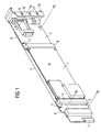
- Figure 1 shows an oblique view of the three-part module insert. This has a middle assembly 1 Controller, which is connected on both sides with external modules 2 and 3 is contacted via plug connections 4.
- the controller 1 is usually purchased as a standard part.
- the outer Modules 2 and 3 are adapters that can be used of standard controllers.
- the carrier means 5 is a rigid support plate with which all three modules 1, 2 and 3 are screwed together.
- the both adapters 2 and 3 point over the top of the carrier 5 projecting edges 6, which a guided Insert the module insert into standard edge guides allow.
- a plug 7 is arranged, which when inserting the module insert a mating connector on a rear wall of a Servers or a computer unit contacted.
- the rear adapter 3 in the direction of insertion is with a panel 8 provided, which ensures the electromagnetic shielding.
- cover A is on the side with contact elements 9 equipped, which the housing into which the module insert is plugged in, contact.
- the Aperture 8 further provided a knurled screw 10, through which the module insert is fixed to the housing can be.
- the carrier means 5 is in the area in which it Controller 1 receives a U-shaped design.
- the two adapters 2 and 3 are connected by a cable connected, this between the carrier means 5 and the Assemblies 1 to 3 are guided in a defined manner.
- slots 11 are formed on the adapters, through which the cables in the space between carrier means 5 and the modules 1 to 3 can be performed.
- FIG. 2 shows the complete module insert according to FIG. 1 in the side view.
- the Adapters 2 and 3 are much wider than controller 1 are.
- the adapters 2 and 3 also point upwards protruding edges 6 over the outline of the carrier means 5 through which a guided insertion of the plug-in module guaranteed in normal standardized card guides is.
- FIG. 3 shows the carrier means 5 in an oblique view. as already mentioned for Figure 1, as a dimensionally stable support plate executed and provided with large openings 10 so that a good heat radiation from the assemblies is guaranteed.
- a cooling plate 13 with a cooling grille 14 is provided, which leads to increased cooling of the controller contributes.
- the carrier means 5 is provided with a series of screw eyes 15 provided on which the modules 1 to 3 are determined.
- FIG. 4 shows how the carrier means 5 is attached by means of screws 16 the controller 1 is screwed on.
- FIG. 5 shows the view according to FIG. 4, wherein the controller 1 is already screwed to the carrier means 5 and is just a further controller component 17 further screws 18 double-layered on the spacer Controller 1 is screwed on.
- controller 1 is much narrower than the adapter 2 and 3, and the complete module insert only through adapters 2 and 3, it is possible that the controller 1 can vary in size and thus different standard controllers are used can. Only the screw eyes are on the used Controller.
Landscapes
- Engineering & Computer Science (AREA)
- General Engineering & Computer Science (AREA)
- Theoretical Computer Science (AREA)
- Microelectronics & Electronic Packaging (AREA)
- Computer Hardware Design (AREA)
- Physics & Mathematics (AREA)
- General Physics & Mathematics (AREA)
- Mounting Of Printed Circuit Boards And The Like (AREA)
- Connector Housings Or Holding Contact Members (AREA)
Abstract
Description
- 1
- Mittlere Baugruppe (Controller)
- 2
- Äußere Baugruppe (Adapter)
- 3
- Äußere Baugruppe (Adapter)
- 4
- Steckverbindung
- 5
- Trägermittel
- 6
- Vorspringende Kanten
- 7
- Stecker
- 8
- Blende
- 9
- Kontaktelemente
- 10
- Schrauben
- 11
- Schlitze
- 12
- Große Öffnungen
- 13
- Kühlblech
- 14
- Kühlgitter
- 15
- Anschraubaugen
- 16
- Schrauben
- 17
- Controllerkomponente
- 18
- Schrauben
Claims (9)
- Dreiteiliger Baugruppeneinschub, bei dem die drei Baugruppen (1, 2, 3) über ein Trägermittel (5) miteinander verbunden sind,
dadurch gekennzeichnet, daß
zumindest zwei Baugruppen (2, 3) über das Trägermittel (5) vorspringende Kanten (6) aufweisen, welche ein geführtes Einstecken des Baugruppeneinschubes erlauben. - Dreiteiliger Baugruppeneinschub nach Anspruch 1,
dadurch gekennzeichnet, daß
die äußeren beiden Baugruppen (2, 3) die vorspringenden Kanten (6) aufweisen. - Dreiteiliger Baugruppeneinschub nach Anspruch 1 oder 2,
dadurch gekennzeichnet, daß
das Trägermittel (5) als formsteifes Trägerblech ausgebildet ist. - Controllereinschub nach einem der Ansprüche 1 bis 3,
dadurch gekennzeichnet, daß
zwischen dem Trägermittel (5) und der mittleren Baugruppe (1) ein Kühlblech (13) vorgesehen ist. - Dreiteiliger Baugruppeneinschub nach einem der Ansprüche 1 bis 4,
dadurch gekennzeichnet, daß
die äußeren beiden Baugruppen (2, 3) Adapter und die mittlere Baugruppe (1) ein Controller ist. - Dreiteiliger Baugruppeneinschub nach Anspruch 5,
dadurch gekennzeichnet, daß
die Adapter (2, 3) breiter als der Controller (1) ausgebildet sind. - Dreiteiliger Baugruppeneinschub nach einem der Ansprüche 1 bis 6,
dadurch gekennzeichnet, daß
eine Kabelverbindung zwischen den äußeren beiden Baugruppen definiert zwischen Trägermittel (5) den Baugruppen (1 bis 3) verlegt ist. - Dreiteiliger Baugruppeneinschub nach einem der Ansprüche 1 bis 7,
dadurch gekennzeichnet, daß
mit der in Steckrichtung hinteren Baugruppe eine Blende (8) verbunden ist, die nach dem Einstecken des Baugruppeneinschubes das aufnehmende Gehäuse leitend kontaktiert. - Dreiteiliger Baugruppeneinschub nach Anspruch 8,
dadurch gekennzeichnet, daß
der Baugruppeneinschub mechanisch über eine an der Blende (8) angeordnete Schraube (10) mit dem Gehäuse verriegelbar ist.
Applications Claiming Priority (2)
| Application Number | Priority Date | Filing Date | Title |
|---|---|---|---|
| DE10105604 | 2001-02-06 | ||
| DE2001105604 DE10105604A1 (de) | 2001-02-06 | 2001-02-06 | Dreiteilinger Baugruppeneinschub |
Publications (2)
| Publication Number | Publication Date |
|---|---|
| EP1229774A2 true EP1229774A2 (de) | 2002-08-07 |
| EP1229774A3 EP1229774A3 (de) | 2006-08-09 |
Family
ID=7673208
Family Applications (1)
| Application Number | Title | Priority Date | Filing Date |
|---|---|---|---|
| EP02000696A Withdrawn EP1229774A3 (de) | 2001-02-06 | 2002-01-11 | Dreiteiliger Baugruppeneinschub |
Country Status (2)
| Country | Link |
|---|---|
| EP (1) | EP1229774A3 (de) |
| DE (1) | DE10105604A1 (de) |
Citations (3)
| Publication number | Priority date | Publication date | Assignee | Title |
|---|---|---|---|---|
| GB905618A (en) * | 1958-06-09 | 1962-09-12 | Ass Elect Ind | Improvements relating to mounting arrangements for electrical components |
| DE1897452U (de) * | 1964-05-13 | 1964-07-30 | Olympia Werke Ag | Elektrische steckeinheit mit wechselrahmen. |
| US5576935A (en) * | 1995-03-24 | 1996-11-19 | Compaq Computer Corporation | Common circuit board connectable to multiple alternative single-sided expansion boards |
Family Cites Families (10)
| Publication number | Priority date | Publication date | Assignee | Title |
|---|---|---|---|---|
| AT309576B (de) * | 1971-06-08 | 1973-08-27 | Itt Austria | Einrichtung mit mehreren parallelen einschiebbaren Platten |
| IT1027159B (it) * | 1974-12-23 | 1978-11-20 | Applic Elettro Telefoniche Aet | Dispositivo di collegamento per circuiti di telecomunicazione in particolape per il loro sezionamento |
| DE3402644A1 (de) * | 1984-01-26 | 1985-08-01 | Siemens AG, 1000 Berlin und 8000 München | Baugruppe zum einschieben in baugruppentraegern der nachrichtentechnik |
| US5648891A (en) * | 1995-08-23 | 1997-07-15 | Rockwell International Corp. | Circuit board assembly |
| US6122161A (en) * | 1995-08-23 | 2000-09-19 | Rockwell Semiconductor Systems, Inc. | Circuit board assembly |
| FR2764473A1 (fr) * | 1997-06-04 | 1998-12-11 | Trt Lucent Technologies | Tiroir electronique comportant un dispositif ameliore d'evacuation de chaleur |
| US5909359A (en) * | 1997-09-22 | 1999-06-01 | Motorola, Inc. | Apparatus for a circuit board extender |
| TW433648U (en) * | 1998-06-04 | 2001-05-01 | Molex Inc | Electrical converter module |
| US6118667A (en) * | 1998-10-22 | 2000-09-12 | International Business Machines Corporation | Card insulator and guide for a computer system having hot plugable adapter cards |
| DE19912858A1 (de) * | 1999-03-22 | 2000-10-19 | Tyco Electronics Logistics Ag | System mit zusammensteckbaren Leiterplatten |
-
2001
- 2001-02-06 DE DE2001105604 patent/DE10105604A1/de not_active Withdrawn
-
2002
- 2002-01-11 EP EP02000696A patent/EP1229774A3/de not_active Withdrawn
Patent Citations (3)
| Publication number | Priority date | Publication date | Assignee | Title |
|---|---|---|---|---|
| GB905618A (en) * | 1958-06-09 | 1962-09-12 | Ass Elect Ind | Improvements relating to mounting arrangements for electrical components |
| DE1897452U (de) * | 1964-05-13 | 1964-07-30 | Olympia Werke Ag | Elektrische steckeinheit mit wechselrahmen. |
| US5576935A (en) * | 1995-03-24 | 1996-11-19 | Compaq Computer Corporation | Common circuit board connectable to multiple alternative single-sided expansion boards |
Also Published As
| Publication number | Publication date |
|---|---|
| EP1229774A3 (de) | 2006-08-09 |
| DE10105604A1 (de) | 2002-08-22 |
Similar Documents
| Publication | Publication Date | Title |
|---|---|---|
| AT392386B (de) | Elektronisches geraet | |
| EP0195955B1 (de) | Rückwandverdrahtung für elektrische Baugruppen | |
| EP1579747B1 (de) | Messgerätmodule und messgerät | |
| WO1997034453A1 (de) | Baugruppe eines elektrischen gerätes | |
| DE68915296T2 (de) | Baugruppe für eine elektronische Vorrichtung. | |
| DE2845884C2 (de) | Träger für einschiebbare elektrische Baugruppen | |
| EP0474082A1 (de) | Codiervorrichtung mit integrierten Sonderkontakten für auf eine Rückwandverdrahtung aufsteckbare elektrische Baugruppen | |
| EP1237395B1 (de) | Leiterplattenanordnung | |
| EP0576857A1 (de) | Codiereinrichtung für elektrische Baugruppen | |
| EP0299199A2 (de) | Baugruppenrahmen zur Aufnahme von einschiebbaren elektrischen Leiterplatten | |
| EP1705975B1 (de) | Messgerät | |
| DE1949412A1 (de) | Chassis fuer elektronische Geraete | |
| DE69623359T2 (de) | Anschlussblock zur elektrischen Verbindung von Ein- und Ausgangssignalen des Moduls eines Hauptspeichers mit externen Vorrichtungen sowie System mit einem solchen Anschlussblock | |
| DE2209858A1 (de) | Einschub fuer schalttafeln oder -schraenke | |
| DE10105604A1 (de) | Dreiteilinger Baugruppeneinschub | |
| EP0863691B1 (de) | Elektrisches Gerät | |
| CH607542A5 (en) | Printed circuit board mechanical coding system | |
| DE2613704C2 (de) | Elektrische Steckvorrichtung | |
| DE7207854U (de) | Einschub für Schalttafeln oder -schranke | |
| DE8905361U1 (de) | Codiervorrichtung für auf eine Rückwandverdrahtung aufsteckbare elektrische Baugruppe | |
| DE2707975C3 (de) | Aus elektrischen Baugruppen und einem Chassis gebildete Funktionseinheit | |
| DE3833235C2 (de) | ||
| DE8900463U1 (de) | Baugruppen-Gehäuse und Stromversorgung | |
| EP0474081B1 (de) | Codiervorrichtung für auf eine Rückwandverdrahtung aufsteckbare elektrische Baugruppen | |
| DE3533810A1 (de) | Adapter zum pruefen von leiterplatten-baugruppen |
Legal Events
| Date | Code | Title | Description |
|---|---|---|---|
| PUAI | Public reference made under article 153(3) epc to a published international application that has entered the european phase |
Free format text: ORIGINAL CODE: 0009012 |
|
| AK | Designated contracting states |
Kind code of ref document: A2 Designated state(s): AT BE CH CY DE DK ES FI FR GB GR IE IT LI LU MC NL PT SE TR |
|
| AX | Request for extension of the european patent |
Free format text: AL;LT;LV;MK;RO;SI |
|
| RAP1 | Party data changed (applicant data changed or rights of an application transferred) |
Owner name: FUJITSU SIEMENS COMPUTERS GMBH |
|
| PUAL | Search report despatched |
Free format text: ORIGINAL CODE: 0009013 |
|
| AK | Designated contracting states |
Kind code of ref document: A3 Designated state(s): AT BE CH CY DE DK ES FI FR GB GR IE IT LI LU MC NL PT SE TR |
|
| AX | Request for extension of the european patent |
Extension state: AL LT LV MK RO SI |
|
| RIC1 | Information provided on ipc code assigned before grant |
Ipc: G06F 13/40 20060101AFI20060630BHEP |
|
| 17P | Request for examination filed |
Effective date: 20070131 |
|
| AKX | Designation fees paid |
Designated state(s): DE FR GB |
|
| 17Q | First examination report despatched |
Effective date: 20090604 |
|
| RAP1 | Party data changed (applicant data changed or rights of an application transferred) |
Owner name: FUJITSU TECHNOLOGY SOLUTIONS INTELLECTUAL PROPERTY |
|
| STAA | Information on the status of an ep patent application or granted ep patent |
Free format text: STATUS: THE APPLICATION IS DEEMED TO BE WITHDRAWN |
|
| 18D | Application deemed to be withdrawn |
Effective date: 20120801 |