EP1228994B1 - Dispositif de transport de feuilles - Google Patents
Dispositif de transport de feuilles Download PDFInfo
- Publication number
- EP1228994B1 EP1228994B1 EP02001294A EP02001294A EP1228994B1 EP 1228994 B1 EP1228994 B1 EP 1228994B1 EP 02001294 A EP02001294 A EP 02001294A EP 02001294 A EP02001294 A EP 02001294A EP 1228994 B1 EP1228994 B1 EP 1228994B1
- Authority
- EP
- European Patent Office
- Prior art keywords
- station
- independent motor
- reductor
- sheets
- converting
- Prior art date
- Legal status (The legal status is an assumption and is not a legal conclusion. Google has not performed a legal analysis and makes no representation as to the accuracy of the status listed.)
- Expired - Lifetime
Links
- 239000002699 waste material Substances 0.000 claims abstract description 7
- 230000001360 synchronised effect Effects 0.000 claims abstract description 5
- 230000001133 acceleration Effects 0.000 claims description 11
- 239000011111 cardboard Substances 0.000 claims description 3
- 239000011087 paperboard Substances 0.000 claims description 3
- 239000000463 material Substances 0.000 abstract 1
- 238000005520 cutting process Methods 0.000 description 11
- 238000006073 displacement reaction Methods 0.000 description 3
- 230000004048 modification Effects 0.000 description 3
- 238000012986 modification Methods 0.000 description 3
- 238000007493 shaping process Methods 0.000 description 3
- 230000008878 coupling Effects 0.000 description 2
- 238000010168 coupling process Methods 0.000 description 2
- 238000005859 coupling reaction Methods 0.000 description 2
- 230000007547 defect Effects 0.000 description 2
- 230000008859 change Effects 0.000 description 1
- 239000003638 chemical reducing agent Substances 0.000 description 1
- 238000010586 diagram Methods 0.000 description 1
- 230000003100 immobilizing effect Effects 0.000 description 1
- 238000002513 implantation Methods 0.000 description 1
- 238000003780 insertion Methods 0.000 description 1
- 230000037431 insertion Effects 0.000 description 1
- 230000007246 mechanism Effects 0.000 description 1
- 239000000123 paper Substances 0.000 description 1
- 230000002035 prolonged effect Effects 0.000 description 1
Images

Classifications
-
- B—PERFORMING OPERATIONS; TRANSPORTING
- B65—CONVEYING; PACKING; STORING; HANDLING THIN OR FILAMENTARY MATERIAL
- B65H—HANDLING THIN OR FILAMENTARY MATERIAL, e.g. SHEETS, WEBS, CABLES
- B65H29/00—Delivering or advancing articles from machines; Advancing articles to or into piles
- B65H29/02—Delivering or advancing articles from machines; Advancing articles to or into piles by mechanical grippers engaging the leading edge only of the articles
- B65H29/04—Delivering or advancing articles from machines; Advancing articles to or into piles by mechanical grippers engaging the leading edge only of the articles the grippers being carried by endless chains or bands
- B65H29/042—Intermediate conveyors, e.g. transferring devices
- B65H29/044—Intermediate conveyors, e.g. transferring devices conveying through a machine
-
- B—PERFORMING OPERATIONS; TRANSPORTING
- B65—CONVEYING; PACKING; STORING; HANDLING THIN OR FILAMENTARY MATERIAL
- B65H—HANDLING THIN OR FILAMENTARY MATERIAL, e.g. SHEETS, WEBS, CABLES
- B65H2301/00—Handling processes for sheets or webs
- B65H2301/40—Type of handling process
- B65H2301/44—Moving, forwarding, guiding material
- B65H2301/449—Features of movement or transforming movement of handled material
- B65H2301/4493—Features of movement or transforming movement of handled material intermittent
-
- B—PERFORMING OPERATIONS; TRANSPORTING
- B65—CONVEYING; PACKING; STORING; HANDLING THIN OR FILAMENTARY MATERIAL
- B65H—HANDLING THIN OR FILAMENTARY MATERIAL, e.g. SHEETS, WEBS, CABLES
- B65H2403/00—Power transmission; Driving means
- B65H2403/90—Machine drive
- B65H2403/94—Other features of machine drive
- B65H2403/943—Electronic shaft arrangement
-
- B—PERFORMING OPERATIONS; TRANSPORTING
- B65—CONVEYING; PACKING; STORING; HANDLING THIN OR FILAMENTARY MATERIAL
- B65H—HANDLING THIN OR FILAMENTARY MATERIAL, e.g. SHEETS, WEBS, CABLES
- B65H2513/00—Dynamic entities; Timing aspects
- B65H2513/20—Acceleration or deceleration
-
- B—PERFORMING OPERATIONS; TRANSPORTING
- B65—CONVEYING; PACKING; STORING; HANDLING THIN OR FILAMENTARY MATERIAL
- B65H—HANDLING THIN OR FILAMENTARY MATERIAL, e.g. SHEETS, WEBS, CABLES
- B65H2513/00—Dynamic entities; Timing aspects
- B65H2513/40—Movement
-
- B—PERFORMING OPERATIONS; TRANSPORTING
- B65—CONVEYING; PACKING; STORING; HANDLING THIN OR FILAMENTARY MATERIAL
- B65H—HANDLING THIN OR FILAMENTARY MATERIAL, e.g. SHEETS, WEBS, CABLES
- B65H2513/00—Dynamic entities; Timing aspects
- B65H2513/50—Timing
-
- B—PERFORMING OPERATIONS; TRANSPORTING
- B65—CONVEYING; PACKING; STORING; HANDLING THIN OR FILAMENTARY MATERIAL
- B65H—HANDLING THIN OR FILAMENTARY MATERIAL, e.g. SHEETS, WEBS, CABLES
- B65H2553/00—Sensing or detecting means
- B65H2553/51—Encoders, e.g. linear
-
- B—PERFORMING OPERATIONS; TRANSPORTING
- B65—CONVEYING; PACKING; STORING; HANDLING THIN OR FILAMENTARY MATERIAL
- B65H—HANDLING THIN OR FILAMENTARY MATERIAL, e.g. SHEETS, WEBS, CABLES
- B65H2701/00—Handled material; Storage means
- B65H2701/10—Handled articles or webs
- B65H2701/17—Nature of material
- B65H2701/176—Cardboard
-
- B—PERFORMING OPERATIONS; TRANSPORTING
- B65—CONVEYING; PACKING; STORING; HANDLING THIN OR FILAMENTARY MATERIAL
- B65H—HANDLING THIN OR FILAMENTARY MATERIAL, e.g. SHEETS, WEBS, CABLES
- B65H2801/00—Application field
- B65H2801/42—Die-cutting
Definitions
- the present invention relates to a sheet conveying device, in a press for forming sheets of paper or cardboard comprising at least one sheet feeding station, a forming station, a waste ejection station and a station for receiving the shaped sheets, said transport device comprising two endless chain trains arranged to transport the sheets from the introduction station to the receiving station, a transverse drive shaft carrying drive wheels of the endless chain trains and at least one sheet gripper attached to the endless chain trains.
- transverse here designates a direction horizontal and perpendicular to the machine axis.
- a single electric motor usually drives the entire machine.
- This motor directly drives a flywheel, a clutch-brake device being interposed between this wheel and the rest of the machine.
- This system drives all the elements operating in synchronism, in particular the movable bed base of the cutting board, the waste ejection and receiving stations, as well as the chain trains carrying the gripper bars for gripping and transporting. leaves from one station to the next.
- a training and forming cycle of a sheet comprises a stopping phase of the sheet during which it undergoes a shaping operation, such as cutting or ejecting waste, and at least one movement phase during which the sheet is brought from one station to the next.
- This movement phase necessarily comprises an acceleration phase and a deceleration phase, and, in general, between the two, a phase where the sheet moves at approximately constant speed.
- the patent CH-411.555 proposes to place the drive of the toothed sector under the control of two cams imparting a rocking motion to a lever which, via a connecting rod drives the toothed sector, while among the two elements of the lever cooperating with the two cams, one, which transmits to the toothed sector the movement back empty, is elastically pressed against the cam.
- the cam system makes it possible to modify the law of movement by softening the starting; however, for a given cam set, this motion law can no longer be modified except to change cams.
- the document US-5,348,285 discloses a forming machine, in particular a platen press for sheets of paper or similar objects, operating in phases.
- the machine comprises an introduction of the sheets, a forming station with a cutting board, a waste disposal and a receiving station shaped sheets.
- the leaves are transported from the introduction to the receiving station by an endless chain conveyor equipped with sheet grippers.
- the receiving station includes an endless conveyor belt conveyor to limit leaf deformations.
- the insertion movement of the sheets is synchronized with the movement of the endless belt of the receiving station.
- the object of the present invention is to provide a device for transporting sheets allowing high speeds while allowing to achieve at will an optimal training cycle leaves without too violent accelerations likely to break the points of attachment between the poses composing a leaf.
- Another object of the invention is to allow the modification of the pace of a leaf drive cycle independently of the training cycle of the forming station.
- the modification of the pace of a leaf drive cycle consists in acting on the acceleration and deceleration curves and the respective durations of the phases of a cycle depending on the type of work to be performed, without having to do so. proceed, between two works, exchanges of parts of the device of transport of leaves.
- a sheet conveying device in a paper or cardboard forming press having at least one sheet feeding station, a converting station, a waste ejection station and a station for receiving the shaped sheets, said transport device comprising two endless chain trains arranged to transport the sheets from the introduction station to the receiving station, a transverse drive shaft carrying drive wheels of the endless chain trains and at least one sheet gripper attached to the endless chain trains, a sheet conveying device in which said transverse drive shaft is driven separately from the drive of the other press stations by at least one independent motor , said independent motor being a motor capable of operating by training cycles comprising at least one phase of movement and a deceleration and / or stop phase controlled by a control device, the duration of each drive cycle of the independent motor being equal to the duration of a shaping cycle of said forming station.
- a control device driving the independent motor by delivering a suitable electric current is able to adjust with much more flexibility than a mechanical device, the characteristics of the acceleration phase, the deceleration phase and the stopping phase of the transport device.
- the drive via the independent motor makes it possible in particular to better adjust the relative durations of the phases of movement and stopping of the train of chains with the stopping and moving phases of the cutting plate and, consequently, to reduce the duration of the stop phase of the platen, which increases the overall rate of the machine.
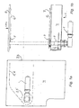
- FIGS. 1a and 1b show an independent motor / gear unit 1 implanted in direct contact with an extension of the transverse drive shaft 2 which carries the driving wheels 3, 3 'endless chain trains 5, 6 of a forming press.
- the motor is located at the compartment 4 which, in a prior art forming press, contained the parts of the mechanical drive device of the chain trains 5, 6 and the coupling parts with the motor driving the various stations of the press, parts which are here suppressed.
- This independent motor / gearbox 1 can be implanted without modification of the whole of an existing machine.
- the motor can also be implanted in a so-called “mirrored” position, that is to say on the opposite end of the transverse drive shaft of the chain train, so also in the so-called “driver's side” position CC in position "opposite side to driver” COC.
- the independent motor / gearbox 1 can also be mounted in a position between the frames 7, 8 and drive the transverse shaft 2 by known means such as pinions, belts, chains, which makes it possible to remove the lateral compartment or compartments 4. drive and gain space.
- the independent motor / gearbox driving the endless chain trains 5, 6 is preferably a high dynamic control electric motor.
- This independent motor / gearbox 1 can be chosen from synchronous, asynchronous, DC, brake or non-brake motors, commercially available.
- a synchronous brushless drive comprising a motor of the HXA60VH type marketed by ABB Normelec SA (Switzerland) enabled the endless chain trains 5, 6 d to be driven. a forming press at high speeds, by eliminating the original mechanical drives of this machine.
- Several manufacturers offer electric motors in standard versions that can develop torques of 200-500 Nm, making it possible to reach chain train acceleration from 25 to 70m / s 2 . The cost of such standard motors is lower than the cost of all mechanical parts of known devices.
- the figure 2 shows the circuit diagram of the electronic control device of the independent motor / gearbox 1.
- the control device, CDE receives from an absolute and incremental encoder 9 a signal giving the exact position of the cutting board 10, this signal serving as real master to the entire system.
- the command CDE also receives from an absolute and incremental encoder the absolute position of the string trains 5, 6; the command CDE finally receives the angular position of the independent motor / gearbox 1 detected by the absolute and incremental encoder 12.
- the comparison of these signals enables the electronic control CDE to determine exactly the locking and unlocking times of the independent motor / gearbox 1 , that is to say to determine the beginning and the end of the stopping phase and to give the current / voltage supply instructions determining, at all times, the accelerations and the speeds of the independent motor / gearbox 1.
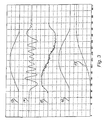
- the figure 3 shows on the same graph five curves 13 to 17, showing in arbitrary units, for the curve 13, the voltage, for the curve 14, the intensity of the current supplying the motor / independent reducer 1, for the curve 15, the acceleration for the curve 16, the speed obtained as well as for the curve 17, the angular displacement of the independent motor / gearbox 1.
- the x-axis represents the angular rotation of the independent motor / gearbox 1 over one revolution, ie 360 ° which correspond to the progress of a sheet from one station to the next.
- these curves show the correspondence between setpoint voltage and speed as well as the absence of excessive accelerations.
Landscapes
- Engineering & Computer Science (AREA)
- Mechanical Engineering (AREA)
- Discharge By Other Means (AREA)
- Delivering By Means Of Belts And Rollers (AREA)
- Feeding Of Articles By Means Other Than Belts Or Rollers (AREA)
- Advancing Webs (AREA)
- Perforating, Stamping-Out Or Severing By Means Other Than Cutting (AREA)
- Forming Counted Batches (AREA)
- Belt Conveyors (AREA)
- Control Of Multiple Motors (AREA)
- Sheets, Magazines, And Separation Thereof (AREA)
Description
- La présente invention concerne un dispositif de transport de feuilles, dans une presse de façonnage de feuilles de papier ou de carton comportant au moins une station d'introduction des feuilles, une station de façonnage, une station d'éjection des déchets et une station de réception des feuilles façonnées, ledit dispositif de transport comprenant deux trains de chaînes sans fin agencés pour transporter les feuilles de la station d'introduction à la station de réception, un arbre d'entraînement transversal portant des roues menantes des trains de chaînes sans fin et au moins un dispositif de saisie de feuilles attaché aux trains de chaînes sans fin.
- Le terme "transversal" désigne ici une direction horizontale et perpendiculaire à l'axe machine.
- Dans les presses de façonnage connues, un seul moteur électrique entraîne usuellement l'ensemble de la machine. Ce moteur entraîne directement un volant d'inertie, un dispositif d'embrayage-frein étant intercalé entre ce volant et le reste de la machine. Ce système entraîne tous les éléments fonctionnant en synchronisme, notamment le sommier mobile de la platine de découpe, les stations d'éjection des déchets et de réception des poses, ainsi que les trains de chaînes portant les barres de pinces assurant la saisie et le transport des feuilles d'une station à la suivante.
- Un cycle d'entraînement et de façonnage d'une feuille comprend une phase d'arrêt de la feuille pendant laquelle elle subit une opération de façonnage, telle que découpe ou éjection de déchets, et au moins une phase de mouvement pendant laquelle la feuille est amenée d'une station à la suivante. Cette phase de mouvement comprend nécessairement une phase d'accélération et une phase de décélération, et, en général, entre les deux, une phase où la feuille se déplace à vitesse à peu près constante.
- Divers mécanismes réalisant ce type de cycle ont déjà été proposés, dans lesquels les roues menant les chaînes sont solidaires en rotation d'un organe d'accouplement qui, par déplacement axial alternativement se met en prise ou se dégage d'un organe d'entraînement, en même temps que des moyens d'immobilisation libèrent ou immobilisent les roues menant les chaînes, tandis que l'organe d'entraînement est alternativement entraîné dans l'un et l'autre sens de rotation.
- De tels dispositifs mécaniques ont été décrits par exemple dans les brevets
CH- 219.422 CH- 411.555 - Par ce type d'entraînement mécanique, on est lié à une loi de mouvement unique, déterminé par la géométrie des pièces. Ce type d'entraînement est bien adapté aux cadences basses ou moyennes jusqu'à environ 5'000-6'000 feuilles/heure ; au-delà, les accélérations et décélérations au début et à la fin de la phase de mouvement deviennent très violentes. Or, après l'opération de découpe de la feuille en poses, ces dernières ne sont plus liées entre elles que par les points d'attache, qui peuvent se rompre en cas d'accélération brutale, provoquant un bourrage de la machine.
- Plusieurs dispositifs mécaniques ont été proposés pour remédier à ce défaut. Le brevet
CH- 411.555 - On connaît aussi des dispositifs dans lesquels on a tenté de supprimer le temps d'arrêt nécessaire à l'opération de découpe. Dans l'un de ces dispositifs, le constructeur a imaginé de donner un mouvement linéaire aux deux sommiers de la station de découpage de sorte que ceux-ci accompagnent le déplacement de la feuille en cours de découpage, solution qui permettait de supprimer le temps d'arrêt en modulant le mouvement linéaire de déplacement des trains de chaînes sans fin.
- Le document
US- 5.348.285 décrit une machine de façonnage, notamment une presse à platine pour feuilles de papier ou objets analogues, fonctionnant par phases. La machine comprend une introduction des feuilles, une station de façonnage avec une platine de découpe, une déjection des déchets et une station de réception des feuilles façonnées. Les feuilles sont transportées de l'introduction à la station de réception par un convoyeur à chaîne sans fin équipé avec des dispositifs de saisie de feuilles. La station de réception comprend un transport vacuum à courroie sans fin, pour limiter des déformations des feuilles. Le mouvement d'introduction des feuilles est synchronisé avec le déplacement de la courroie sans fin de la station de réception. - Le but de la présente invention est de proposer un dispositif de transport de feuilles autorisant des cadences élevées tout en permettant de réaliser à volonté un cycle d'entraînement optimal des feuilles sans accélérations trop violentes susceptibles de rompre les points d'attaches entre les poses composant une feuille. Un autre but de l'invention est de permettre la modification de l'allure d'un cycle d'entraînement des feuilles indépendamment du cycle d'entraînement de la station de façonnage. La modification de l'allure d'un cycle d'entraînement des feuilles consiste à agir sur les courbes d'accélération et de décélération et les durées respectives des phases d'un cycle en fonction du type de travail à exécuter, sans pour cela devoir procéder, entre deux travaux, à des échanges de pièces du dispositif de transport de feuilles.
- Ces buts sont atteints par un dispositif de transport de feuilles, dans une presse de façonnage de feuilles de papier ou de carton comportant au moins une station d'introduction des feuilles, une station de façonnage, une station d'éjection des déchets et une station de réception des feuilles façonnées, ledit dispositif de transport comprenant deux trains de chaînes sans fin agencés pour transporter les feuilles de la station d'introduction à la station de réception, un arbre d'entraînement transversal portant des roues menantes des trains de chaînes sans fin et au moins un dispositif de saisie de feuilles attaché aux trains de chaînes sans fin, dispositif de transport de feuilles dans lequel ledit arbre d'entraînement transversal est entraîné séparément de l'entraînement des autres stations de la presse, par au moins un moteur indépendant, ledit moteur indépendant étant un moteur capable de fonctionner par cycles d'entraînement comprenant au moins une phase de mouvement et une phase de décélération et/ou d'arrêt commandées par un dispositif de commande, la durée de chaque cycle d'entraînement du moteur indépendant étant égale à la durée d'un cycle de façonnage de ladite station de façonnage.
- Le fait d'entraîner le dispositif de transport de feuilles par un moteur autonome au lieu de l'entraîner par le même moteur que les autres stations de la presse de façonnage se heurtait à un préjugé, à savoir la crainte d'un défaut de synchronisation entre l'avance séquentielle des feuilles et le fonctionnement de la platine de découpe des stations en aval. Les inventeurs ont constaté au contraire qu'une commande, notamment une commande électronique, qui reçoit un signal représentatif de la position de la platine de la station de découpe et un signal représentatif de la position du train de chaînes permet de commander le moteur indépendant pilotant l'avancement du train de chaînes en synchronisme parfait avec le cycle de la platine. A l'intérieur d'un cycle d'entraînement, un dispositif de commande pilotant le moteur indépendant par délivrance d'un courant électrique approprié est capable d'ajuster avec beaucoup plus de souplesse que ne pourrait le faire un dispositif mécanique, les caractéristiques de la phase d'accélération, de la phase de décélération et de la phase d'arrêt du dispositif de transport. L'entraînement par l'intermédiaire du moteur indépendant permet en particulier de mieux ajuster les durées relatives des phases de mouvement et d'arrêt du train de chaînes avec les phases d'arrêt et de mouvement de la platine de découpe et, par conséquent, de diminuer la durée de la phase d'arrêt de la platine, ce qui permet d'augmenter la cadence d'ensemble de la machine.
- D'autres particularités et avantages de l'invention apparaîtront à l'homme du métier à la lecture de la description d'un mode d'exécution, en se référant au dessin, dans lequel;
- les
figures 1a et 1b montrent l'implantation d'un moteur d'entraînement d'un dispositif de transport dans une presse de façonnage, respectivement en vue latérale et en vue de dessus; - la
figure 2 est une vue schématique du dispositif de commande de ce moteur; - la
figure 3 représente l'enregistrement des caractéristiques d'un cycle. - Les
figures 1a et 1b montrent un ensemble moteur/réducteur indépendant 1 implanté en prise directe avec un prolongement de l'arbre d'entraînement transversal 2 qui porte les roues menantes 3, 3' des trains de chaînes sans fin 5, 6 d'une presse de façonnage. Comme le montre notamment lafigure 1a , le moteur est implanté au niveau du compartiment 4 qui, dans une presse de façonnage de l'art antérieur, contenait les pièces du dispositif d'entraînement mécanique des trains de chaînes 5, 6 et les pièces d'accouplement avec le moteur entraînant les diverses stations de la presse, pièces qui sont ici supprimées. Ce moteur/réducteur indépendant 1 peut donc être implanté sans modification de l'ensemble d'une machine existante. L'homme du métier comprendra aisément que le moteur peut également être implanté dans une position dite "en miroir", c'est-à-dire sur l'extrémité opposée de l'arbre d'entraînement transversal du train de chaînes, donc aussi bien en position dite "côté conducteur" CC qu'en position "côté opposé au conducteur" COC. Le moteur/réducteur indépendant 1 peut aussi être monté dans une position entre les bâtis 7, 8 et entraîner l'arbre transversal 2 par des moyens connus tels que pignons, courroies, chaînes, ce qui permet de supprimer le ou les compartiments latéraux 4 d'entraînement et de gagner en encombrement. - Le moteur/réducteur indépendant entraînant les trains de chaînes sans fin 5, 6 est de préférence un moteur électrique de régulation à haute dynamique. Ce moteur/réducteur indépendant 1 peut être choisi parmi les moteurs synchrones, asynchrones, à courant continu, avec frein ou sans frein, commercialement disponibles. A titre d'exemple, lors d'essais effectués par le déposant, un entraînement brushless synchrone comportant un moteur de type HXA60VH commercialisé par la société ABB Normelec S.A. (Suisse) a permis d'entraîner les trains de chaînes sans fin 5, 6 d'une presse de façonnage à des cadences importantes, en supprimant les entraînements mécaniques d'origine de cette machine. Plusieurs fabricants offrent des moteurs électriques en exécutions standard pouvant développer des couples de 200-500 Nm, permettant d'atteindre des accélérations des trains de chaînes de 25 à 70m/s2. Le coût de tels moteurs standards est inférieur au coût de l'ensemble des pièces mécaniques des dispositifs connus.
- La
figure 2 montre le schéma de principe du dispositif de commande électronique du moteur/réducteur indépendant 1. Le dispositif de commande, CDE, reçoit d'un codeur absolu et incrémentiel 9 un signal donnant la position exacte de la platine de découpe 10, ce signal servant de maître réel à l'ensemble du système. La commande CDE reçoit également d'un codeur absolu et incrémentiel 11 la position absolue des trains de chaînes 5, 6; la commande CDE reçoit enfin la position angulaire du moteur/réducteur indépendant 1 détectée par le codeur absolu et incrémentiel 12. La comparaison de ces signaux permet à la commande électronique CDE de déterminer exactement les temps de blocage et de déblocage du moteur/réducteur indépendant 1, c'est-à-dire de déterminer le début et la fin de la phase d'arrêt et de donner les consignes d'alimentation courant/tension déterminant, à tout instant, les accélérations et les vitesses du moteur/réducteur indépendant 1. - La
figure 3 montre sur un même graphique cinq courbes 13 à 17, montrant en unités arbitraires, pour la courbe 13, la tension, pour la courbe 14, l'intensité du courant alimentant le moteur/réducteur indépendant 1, pour la courbe 15, l'accélération, pour la courbe 16, la vitesse obtenue ainsi que pour la courbe 17, le déplacement angulaire du moteur/réducteur indépendant 1. Dans cette figure, l'axe des abscisses représente la rotation angulaire du moteur/réducteur indépendant 1 sur un tour, soit 360° qui correspondent à l'avancement d'une feuille d'une station à la suivante immédiate. - On constate notamment sur ces courbes la correspondance entre tension de consigne et vitesse ainsi que l'absence d'accélérations excessives. Par modification de la courbe de tension préprogrammée, on peut aisément supprimer la phase de mouvement à vitesse constante, prolonger ou raccourcir la durée de la phase de mouvement à l'intérieur d'un cycle.
Claims (5)
- Dispositif de transport de feuilles, dans une presse de façonnage de feuilles de papier ou de carton comportant au moins une station d'introduction des feuilles, une station de façonnage comprenant une platine de découpe (10), une station d'éjection des déchets et une station de réception des feuilles façonnées, ledit dispositif de transport comprenant deux trains de chaînes sans fin (5, 6) agencés pour transporter les feuilles de la station d'introduction a la station de réception, un arbre d' entraînement transversal (2) portant des roues menantes (3, 3') des trains de chaires sans fin (5, 6) et au moins un dispositif de saisie de feuilles attaché aux trains de chaînes sans fin (5, 6), caractérisé en ce que ledit arbre d'entraînement transversal (2) est entraîné séparément de l'entraînement des autres stations de la presse, par au moins un moteur/réducteur indépendant (1), électrique de régulation à haute dynamique capable de fonctionner par cycles d'entraînement comprenant au moins une phase de mouvement et une phase de décélération et/ou une phase d'arrêt, lesdites phases étant commandées en fonction de la position exacte de la platine de découpe (10), par un dispositif de commande (CDE), capable d'ajuster, pour chaque cycle d'entraînement, au moins les durées et les amplitudes d'une phase d'accélération, d'une phase de décélération et d'une phase d'arrêt, la durée de chaque cycle d'entraînement du moteur/réducteur indépendant (1) étant égale a la durée d'un cycle de façonnage de ladite station de façonnage, et en ce qu'il comprend un codeur (9) absolu et incrémentiel donnant la position exacte de la platine de découpe (10) , un codeur (11) de position des trains de chaînes sans fin (5, 6) et un codeur (12) de position angulaire du moteur indépendant (1) reliés audit dispositif électronique de commande (CDE).
- Dispositif de transport selon la revendication 1, caractérisé en ce que ledit moteur/réducteur indépendant (1) est choisi parmi les moteurs synchrones, asynchrones, à courant continu, avec frein ou sans frein.
- Dispositif de transport selon la revendication 2 caractérisé en ce que ledit moteur/réducteur indépendant (1) est monté dans le prolongement dudit arbre d'entraînement transversal (2), du côté du conducteur (CC).
- Dispositif de transport selon la revendication 2, caractérisé en ce que ledit moteur/réducteur indépendant (1) est monté dans le prolongement dudit arbre d'entraînement transversal (2) du côté opposé au conducteur (COC).
- Dispositif de transport selon la revendication 2, caractérisé en ce que ledit moteur/réducteur indépendant (1) est monté entre des bâtis (7, 8).
Applications Claiming Priority (2)
| Application Number | Priority Date | Filing Date | Title |
|---|---|---|---|
| CH00179/01A CH694638A5 (fr) | 2001-02-01 | 2001-02-01 | Dispositif de transport de feuilles. |
| CH1792001 | 2001-02-01 |
Publications (3)
| Publication Number | Publication Date |
|---|---|
| EP1228994A2 EP1228994A2 (fr) | 2002-08-07 |
| EP1228994A3 EP1228994A3 (fr) | 2004-03-31 |
| EP1228994B1 true EP1228994B1 (fr) | 2010-07-14 |
Family
ID=4429080
Family Applications (1)
| Application Number | Title | Priority Date | Filing Date |
|---|---|---|---|
| EP02001294A Expired - Lifetime EP1228994B1 (fr) | 2001-02-01 | 2002-01-18 | Dispositif de transport de feuilles |
Country Status (13)
| Country | Link |
|---|---|
| US (2) | US6691997B2 (fr) |
| EP (1) | EP1228994B1 (fr) |
| JP (1) | JP3735072B2 (fr) |
| KR (1) | KR100435248B1 (fr) |
| CN (1) | CN1172835C (fr) |
| AT (1) | ATE473939T1 (fr) |
| AU (1) | AU1471402A (fr) |
| BR (1) | BR0200270B1 (fr) |
| CA (1) | CA2369940C (fr) |
| CH (1) | CH694638A5 (fr) |
| DE (1) | DE60236977D1 (fr) |
| ES (1) | ES2348292T3 (fr) |
| TW (1) | TW536519B (fr) |
Families Citing this family (10)
| Publication number | Priority date | Publication date | Assignee | Title |
|---|---|---|---|---|
| CH694638A5 (fr) * | 2001-02-01 | 2005-05-13 | Bobst Sa | Dispositif de transport de feuilles. |
| DE10343460A1 (de) * | 2002-10-04 | 2004-04-15 | Saurer Gmbh & Co. Kg | Vorrichtung zum Spinnen und Aufwickeln zumindest eines synthetischen Fadens |
| JP2006079723A (ja) * | 2004-09-09 | 2006-03-23 | Funai Electric Co Ltd | 光ディスク装置 |
| JP4182072B2 (ja) * | 2005-03-02 | 2008-11-19 | キヤノン株式会社 | 画像読取装置及び画像伸縮補正方法 |
| DE102006049112A1 (de) | 2006-10-18 | 2008-04-30 | Heidelberger Druckmaschinen Ag | Flachbrett-Bogenstanzmaschine |
| WO2012038035A1 (fr) * | 2010-09-22 | 2012-03-29 | Bobst Sa | Machine de traitement d'elements en feuilles comprenant un tendeur de trains de chaines |
| DE102012020360A1 (de) * | 2012-10-17 | 2014-04-17 | Heidelberger Druckmaschinen Ag | Stanzmaschine mit Überwachungssensor und Verfahren zum Schnellabschalten einer solchen Maschine |
| KR102015746B1 (ko) * | 2016-03-09 | 2019-08-28 | 봅스트 맥스 에스에이 | 체인 텐셔너, 시트 형태 요소들을 프로세싱하기 위한 기계 및 체인들의 세트들을 인장하기 위한 방법 |
| US11772921B2 (en) * | 2017-07-28 | 2023-10-03 | Hp Indigo B.V. | Printing system comprising a transport apparatus engaged with a track and method of printing |
| ES2795099B2 (es) * | 2020-05-07 | 2021-04-19 | Telesforo Gonzalez Maqu Slu | Metodo y maquina para formar cajas de carton por encolado, programa de ordenador, y dispositivo legible por ordenador que tiene almacenado dicho programa |
Family Cites Families (26)
| Publication number | Priority date | Publication date | Assignee | Title |
|---|---|---|---|---|
| CH219422A (fr) | 1941-04-26 | 1942-02-15 | Bobst Fils Sa J | Machine travaillant des feuilles. |
| US3042398A (en) * | 1954-06-15 | 1962-07-03 | S & S Corrugated Paper Mach | Sheet gripping means for cutting and creasing press |
| US3184229A (en) * | 1959-08-28 | 1965-05-18 | Samuel M Langston Co | Intermittent motion drive mechanism |
| CH411555A (fr) * | 1965-03-08 | 1966-04-15 | Bobst Fils Sa J | Machine travaillant des feuilles |
| US4093904A (en) * | 1976-02-04 | 1978-06-06 | Contraves Goerz Corporation | Multi-axis motion generator utilizing feedforward control |
| US4453436A (en) * | 1980-09-03 | 1984-06-12 | Rengo Co., Ltd. | Die cutter and process for die cutting |
| JPS58178137U (ja) * | 1982-05-20 | 1983-11-29 | 株式会社リコー | 複写機における原稿送り装置 |
| JPS58191156U (ja) * | 1982-06-14 | 1983-12-19 | 株式会社リコー | シ−ト搬送装置 |
| JPS5971243A (ja) * | 1982-10-18 | 1984-04-21 | Toshiba Corp | 均一磁界発生装置 |
| JPS6125340U (ja) * | 1984-07-20 | 1986-02-15 | 三菱重工業株式会社 | シ−トの送り出し装置 |
| US4674739A (en) * | 1985-08-02 | 1987-06-23 | Corrugated Paper Machinery Corp. | Sheet transfer device |
| US5142323A (en) * | 1988-05-13 | 1992-08-25 | Ricoh Company, Ltd. | Paper feed control method for a copier |
| JPH03195661A (ja) * | 1989-12-25 | 1991-08-27 | Mitsubishi Electric Corp | 用紙搬送装置 |
| US5141221A (en) * | 1990-11-05 | 1992-08-25 | Heidelberg Harris Gmbh | Deceleration device in the folder of a rotary printing machine |
| DK0511424T3 (da) * | 1991-04-30 | 1995-07-31 | Hirakawa Kogyosha Kk | Transportrullekonstruktion til transport af pladeformede genstande |
| EP0557609B1 (fr) * | 1991-12-19 | 1997-03-12 | SYSTEM KURANDT GmbH | Installation pour le contrÔle en ligne de découpes de boîtes |
| DE4201411A1 (de) * | 1992-01-21 | 1993-07-22 | Blohm Voss Ag | Niederhalter an behandlungsanlagen, insbesondere stanzmaschinen, fuer duenne flache gegenstaende, insbesondere boegen aus papier |
| JP3413954B2 (ja) * | 1994-04-30 | 2003-06-09 | 三菱電機株式会社 | モーションコントローラ |
| DE19640963A1 (de) * | 1996-10-04 | 1998-04-16 | Wolfgang Heiber | Verfahren und Vorrichtung zur Vereinzelung von gestapelten Zuschnitten |
| US5979316A (en) * | 1997-09-30 | 1999-11-09 | Corrugated Gear & Services, Inc. | Belt-driven printer-cutter machine for corrugated paperboard of varying thickness |
| CA2259785C (fr) * | 1999-01-19 | 2008-07-29 | Peter E. Sandford | Membre egaliseur, systeme et procede pour monter un tel membre et suppresseur de teinture male et femelle prevue avec |
| US6358191B1 (en) * | 1999-08-27 | 2002-03-19 | The Mead Corporation | System and method for flexible control and adjustment of a box forming machine |
| CH694219A5 (fr) * | 2000-02-10 | 2004-09-30 | Bobst Sa | Procédé de mise en repérage automatique d'impressions dans une machine rotative et dispositif pour la mise en oeuvre du procédé. |
| US6345171B1 (en) * | 2000-07-11 | 2002-02-05 | Toshiba Tec Kabushiki Kaisha | Image forming apparatus and a method to control paper conveying speeds in image forming apparatus |
| US6370354B1 (en) * | 2000-08-08 | 2002-04-09 | Lexmark International, Inc. | Method and apparatus for controlling media-to-image registration of a single-pass intermediate transfer member-based printing apparatus |
| CH694638A5 (fr) * | 2001-02-01 | 2005-05-13 | Bobst Sa | Dispositif de transport de feuilles. |
-
2001
- 2001-02-01 CH CH00179/01A patent/CH694638A5/fr not_active IP Right Cessation
- 2001-12-27 TW TW090132491A patent/TW536519B/zh not_active IP Right Cessation
-
2002
- 2002-01-18 DE DE60236977T patent/DE60236977D1/de not_active Expired - Lifetime
- 2002-01-18 ES ES02001294T patent/ES2348292T3/es not_active Expired - Lifetime
- 2002-01-18 EP EP02001294A patent/EP1228994B1/fr not_active Expired - Lifetime
- 2002-01-18 AT AT02001294T patent/ATE473939T1/de not_active IP Right Cessation
- 2002-01-22 CN CNB021028036A patent/CN1172835C/zh not_active Expired - Lifetime
- 2002-01-24 US US10/057,064 patent/US6691997B2/en not_active Expired - Lifetime
- 2002-01-29 KR KR10-2002-0005033A patent/KR100435248B1/ko not_active Expired - Fee Related
- 2002-01-30 AU AU14714/02A patent/AU1471402A/en not_active Abandoned
- 2002-01-31 CA CA002369940A patent/CA2369940C/fr not_active Expired - Fee Related
- 2002-01-31 BR BRPI0200270-1A patent/BR0200270B1/pt not_active IP Right Cessation
- 2002-02-01 JP JP2002025090A patent/JP3735072B2/ja not_active Expired - Fee Related
-
2003
- 2003-08-21 US US10/645,138 patent/US6845979B2/en not_active Expired - Lifetime
Also Published As
| Publication number | Publication date |
|---|---|
| CA2369940C (fr) | 2007-12-04 |
| DE60236977D1 (de) | 2010-08-26 |
| US20020101028A1 (en) | 2002-08-01 |
| AU1471402A (en) | 2002-08-08 |
| KR100435248B1 (ko) | 2004-06-11 |
| EP1228994A2 (fr) | 2002-08-07 |
| CH694638A5 (fr) | 2005-05-13 |
| BR0200270A (pt) | 2002-10-08 |
| CA2369940A1 (fr) | 2002-08-01 |
| CN1172835C (zh) | 2004-10-27 |
| US20040036209A1 (en) | 2004-02-26 |
| EP1228994A3 (fr) | 2004-03-31 |
| ATE473939T1 (de) | 2010-07-15 |
| TW536519B (en) | 2003-06-11 |
| JP2002284419A (ja) | 2002-10-03 |
| US6845979B2 (en) | 2005-01-25 |
| US6691997B2 (en) | 2004-02-17 |
| ES2348292T3 (es) | 2010-12-02 |
| JP3735072B2 (ja) | 2006-01-11 |
| CN1369369A (zh) | 2002-09-18 |
| KR20020064171A (ko) | 2002-08-07 |
| BR0200270B1 (pt) | 2010-06-01 |
Similar Documents
| Publication | Publication Date | Title |
|---|---|---|
| FR2562526A1 (fr) | Chargeur de signatures, feuilles et produits similaires pour alimentateurs pour machines de conditionnement, de machines pour la reliure et analogues | |
| CH694638A5 (fr) | Dispositif de transport de feuilles. | |
| EP2356052B1 (fr) | Dispositif d'alimentation d'une unité de transformation avec un support en bande continue pour une station d'alimentation dans une machine de production d'emballages | |
| EP3003703A1 (fr) | Unite de transformation d'un support en bande continue et machine de production d'emballages ainsi equipee | |
| FR2518073A1 (fr) | Appareil pour entrainer des feuilles successivement a partir d'une pile | |
| EP1639907B8 (fr) | Dispositif de transfert d'articles en forme de tige | |
| FR2671759A1 (fr) | Machine rotative d'impression de feuilles. | |
| FR2767540A1 (fr) | Machine de tricotage sur metier chaine, equipee d'une platine a barre de presse | |
| FR2620430A1 (fr) | Dispositif d'alimentation pour des articles en feuille, notamment des feuilles de papier pour la constitution de carton ondule | |
| BE551819A (fr) | ||
| WO2003002435A2 (fr) | Dispositif de transport de pieces pour l'alimentation de machines | |
| FR2502129A1 (fr) | Dispositif pour alimenter en feuilles des machines a faconner les feuilles, notamment des machines a doubler | |
| US6655674B2 (en) | Arrangement for stitching the spine of printed products, compiled of folded printed sheets, by means of staples | |
| FR2691447A1 (fr) | Dispositif de coupe en une pile de feuilles en petits paquets, notamment des billets de banque. | |
| FR2729331A1 (fr) | Tete d'impression offset, et machine a imprimer comportant au moins une telle tete d'impression | |
| EP1534501A1 (fr) | Machine de traitement de feuilles avec des decoupes ou des plis transversaux a leur direction d avancement. | |
| US1040201A (en) | Wrapping-machine. | |
| JPS5834325B2 (ja) | 板状物品の包装方法および装置 | |
| JP2608159B2 (ja) | プラテンプレス装置 | |
| US927224A (en) | Loose-wrap-gluing machine. | |
| EP0655325A2 (fr) | Machine à assembler des boîtes en carton | |
| US588909A (en) | hilqartner | |
| US655695A (en) | Paper-box-making machine. | |
| CH251408A (fr) | Dispositif servant au transport du papier dans une presse d'imprimerie. | |
| EP3366428A1 (fr) | Machine perfectionnee d'agrafage d'angle |
Legal Events
| Date | Code | Title | Description |
|---|---|---|---|
| PUAI | Public reference made under article 153(3) epc to a published international application that has entered the european phase |
Free format text: ORIGINAL CODE: 0009012 |
|
| 17P | Request for examination filed |
Effective date: 20020118 |
|
| AK | Designated contracting states |
Kind code of ref document: A2 Designated state(s): AT BE CH CY DE DK ES FI FR GB GR IE IT LI LU MC NL PT SE TR |
|
| AX | Request for extension of the european patent |
Free format text: AL;LT;LV;MK;RO;SI |
|
| PUAL | Search report despatched |
Free format text: ORIGINAL CODE: 0009013 |
|
| AK | Designated contracting states |
Kind code of ref document: A3 Designated state(s): AT BE CH CY DE DK ES FI FR GB GR IE IT LI LU MC NL PT SE TR |
|
| AX | Request for extension of the european patent |
Extension state: AL LT LV MK RO SI |
|
| RIC1 | Information provided on ipc code assigned before grant |
Ipc: 7B 26D 5/20 B Ipc: 7B 65H 29/04 A Ipc: 7B 26F 1/40 B |
|
| AKX | Designation fees paid |
Designated state(s): AT BE CH CY DE DK ES FI FR GB GR IE IT LI LU MC NL PT SE TR |
|
| 17Q | First examination report despatched |
Effective date: 20050624 |
|
| GRAP | Despatch of communication of intention to grant a patent |
Free format text: ORIGINAL CODE: EPIDOSNIGR1 |
|
| GRAS | Grant fee paid |
Free format text: ORIGINAL CODE: EPIDOSNIGR3 |
|
| GRAA | (expected) grant |
Free format text: ORIGINAL CODE: 0009210 |
|
| AK | Designated contracting states |
Kind code of ref document: B1 Designated state(s): AT BE CH CY DE DK ES FI FR GB GR IE IT LI LU MC NL PT SE TR |
|
| REG | Reference to a national code |
Ref country code: GB Ref legal event code: FG4D Free format text: NOT ENGLISH |
|
| REG | Reference to a national code |
Ref country code: CH Ref legal event code: EP |
|
| REG | Reference to a national code |
Ref country code: IE Ref legal event code: FG4D |
|
| REF | Corresponds to: |
Ref document number: 60236977 Country of ref document: DE Date of ref document: 20100826 Kind code of ref document: P |
|
| REG | Reference to a national code |
Ref country code: NL Ref legal event code: T3 |
|
| REG | Reference to a national code |
Ref country code: ES Ref legal event code: FG2A Effective date: 20101122 |
|
| PG25 | Lapsed in a contracting state [announced via postgrant information from national office to epo] |
Ref country code: AT Free format text: LAPSE BECAUSE OF FAILURE TO SUBMIT A TRANSLATION OF THE DESCRIPTION OR TO PAY THE FEE WITHIN THE PRESCRIBED TIME-LIMIT Effective date: 20100714 Ref country code: FI Free format text: LAPSE BECAUSE OF FAILURE TO SUBMIT A TRANSLATION OF THE DESCRIPTION OR TO PAY THE FEE WITHIN THE PRESCRIBED TIME-LIMIT Effective date: 20100714 |
|
| REG | Reference to a national code |
Ref country code: IE Ref legal event code: FD4D |
|
| PG25 | Lapsed in a contracting state [announced via postgrant information from national office to epo] |
Ref country code: CY Free format text: LAPSE BECAUSE OF FAILURE TO SUBMIT A TRANSLATION OF THE DESCRIPTION OR TO PAY THE FEE WITHIN THE PRESCRIBED TIME-LIMIT Effective date: 20100714 Ref country code: PT Free format text: LAPSE BECAUSE OF FAILURE TO SUBMIT A TRANSLATION OF THE DESCRIPTION OR TO PAY THE FEE WITHIN THE PRESCRIBED TIME-LIMIT Effective date: 20101115 |
|
| PG25 | Lapsed in a contracting state [announced via postgrant information from national office to epo] |
Ref country code: GR Free format text: LAPSE BECAUSE OF FAILURE TO SUBMIT A TRANSLATION OF THE DESCRIPTION OR TO PAY THE FEE WITHIN THE PRESCRIBED TIME-LIMIT Effective date: 20101015 Ref country code: SE Free format text: LAPSE BECAUSE OF FAILURE TO SUBMIT A TRANSLATION OF THE DESCRIPTION OR TO PAY THE FEE WITHIN THE PRESCRIBED TIME-LIMIT Effective date: 20100714 |
|
| PG25 | Lapsed in a contracting state [announced via postgrant information from national office to epo] |
Ref country code: IE Free format text: LAPSE BECAUSE OF FAILURE TO SUBMIT A TRANSLATION OF THE DESCRIPTION OR TO PAY THE FEE WITHIN THE PRESCRIBED TIME-LIMIT Effective date: 20100714 Ref country code: DK Free format text: LAPSE BECAUSE OF FAILURE TO SUBMIT A TRANSLATION OF THE DESCRIPTION OR TO PAY THE FEE WITHIN THE PRESCRIBED TIME-LIMIT Effective date: 20100714 |
|
| PLBE | No opposition filed within time limit |
Free format text: ORIGINAL CODE: 0009261 |
|
| STAA | Information on the status of an ep patent application or granted ep patent |
Free format text: STATUS: NO OPPOSITION FILED WITHIN TIME LIMIT |
|
| 26N | No opposition filed |
Effective date: 20110415 |
|
| REG | Reference to a national code |
Ref country code: DE Ref legal event code: R097 Ref document number: 60236977 Country of ref document: DE Effective date: 20110415 |
|
| BERE | Be: lapsed |
Owner name: BOBST S.A. Effective date: 20110131 |
|
| PG25 | Lapsed in a contracting state [announced via postgrant information from national office to epo] |
Ref country code: MC Free format text: LAPSE BECAUSE OF NON-PAYMENT OF DUE FEES Effective date: 20110131 |
|
| PG25 | Lapsed in a contracting state [announced via postgrant information from national office to epo] |
Ref country code: BE Free format text: LAPSE BECAUSE OF NON-PAYMENT OF DUE FEES Effective date: 20110131 |
|
| PG25 | Lapsed in a contracting state [announced via postgrant information from national office to epo] |
Ref country code: LU Free format text: LAPSE BECAUSE OF NON-PAYMENT OF DUE FEES Effective date: 20110118 |
|
| PGFP | Annual fee paid to national office [announced via postgrant information from national office to epo] |
Ref country code: NL Payment date: 20130110 Year of fee payment: 12 |
|
| PG25 | Lapsed in a contracting state [announced via postgrant information from national office to epo] |
Ref country code: TR Free format text: LAPSE BECAUSE OF FAILURE TO SUBMIT A TRANSLATION OF THE DESCRIPTION OR TO PAY THE FEE WITHIN THE PRESCRIBED TIME-LIMIT Effective date: 20100714 |
|
| REG | Reference to a national code |
Ref country code: NL Ref legal event code: V1 Effective date: 20140801 |
|
| PG25 | Lapsed in a contracting state [announced via postgrant information from national office to epo] |
Ref country code: NL Free format text: LAPSE BECAUSE OF NON-PAYMENT OF DUE FEES Effective date: 20140801 |
|
| REG | Reference to a national code |
Ref country code: FR Ref legal event code: PLFP Year of fee payment: 15 |
|
| REG | Reference to a national code |
Ref country code: FR Ref legal event code: PLFP Year of fee payment: 16 |
|
| REG | Reference to a national code |
Ref country code: FR Ref legal event code: PLFP Year of fee payment: 17 |
|
| PGFP | Annual fee paid to national office [announced via postgrant information from national office to epo] |
Ref country code: CH Payment date: 20190110 Year of fee payment: 18 Ref country code: IT Payment date: 20190121 Year of fee payment: 18 |
|
| REG | Reference to a national code |
Ref country code: CH Ref legal event code: PL |
|
| PG25 | Lapsed in a contracting state [announced via postgrant information from national office to epo] |
Ref country code: CH Free format text: LAPSE BECAUSE OF NON-PAYMENT OF DUE FEES Effective date: 20200131 Ref country code: LI Free format text: LAPSE BECAUSE OF NON-PAYMENT OF DUE FEES Effective date: 20200131 |
|
| PG25 | Lapsed in a contracting state [announced via postgrant information from national office to epo] |
Ref country code: IT Free format text: LAPSE BECAUSE OF NON-PAYMENT OF DUE FEES Effective date: 20200118 |
|
| PGFP | Annual fee paid to national office [announced via postgrant information from national office to epo] |
Ref country code: FR Payment date: 20210106 Year of fee payment: 20 |
|
| PGFP | Annual fee paid to national office [announced via postgrant information from national office to epo] |
Ref country code: GB Payment date: 20210106 Year of fee payment: 20 Ref country code: ES Payment date: 20210208 Year of fee payment: 20 Ref country code: DE Payment date: 20210105 Year of fee payment: 20 |
|
| REG | Reference to a national code |
Ref country code: DE Ref legal event code: R071 Ref document number: 60236977 Country of ref document: DE |
|
| REG | Reference to a national code |
Ref country code: GB Ref legal event code: PE20 Expiry date: 20220117 |
|
| REG | Reference to a national code |
Ref country code: ES Ref legal event code: FD2A Effective date: 20220426 |
|
| PG25 | Lapsed in a contracting state [announced via postgrant information from national office to epo] |
Ref country code: GB Free format text: LAPSE BECAUSE OF EXPIRATION OF PROTECTION Effective date: 20220117 |
|
| PG25 | Lapsed in a contracting state [announced via postgrant information from national office to epo] |
Ref country code: ES Free format text: LAPSE BECAUSE OF EXPIRATION OF PROTECTION Effective date: 20220119 |