US6845979B2 - Independent device for synchronization of sheet operations and conveyancing - Google Patents
Independent device for synchronization of sheet operations and conveyancing Download PDFInfo
- Publication number
- US6845979B2 US6845979B2 US10/645,138 US64513803A US6845979B2 US 6845979 B2 US6845979 B2 US 6845979B2 US 64513803 A US64513803 A US 64513803A US 6845979 B2 US6845979 B2 US 6845979B2
- Authority
- US
- United States
- Prior art keywords
- conveyor
- drive
- operating
- position signal
- press station
- Prior art date
- Legal status (The legal status is an assumption and is not a legal conclusion. Google has not performed a legal analysis and makes no representation as to the accuracy of the status listed.)
- Expired - Lifetime
Links
Images


Classifications
-
- B—PERFORMING OPERATIONS; TRANSPORTING
- B65—CONVEYING; PACKING; STORING; HANDLING THIN OR FILAMENTARY MATERIAL
- B65H—HANDLING THIN OR FILAMENTARY MATERIAL, e.g. SHEETS, WEBS, CABLES
- B65H29/00—Delivering or advancing articles from machines; Advancing articles to or into piles
- B65H29/02—Delivering or advancing articles from machines; Advancing articles to or into piles by mechanical grippers engaging the leading edge only of the articles
- B65H29/04—Delivering or advancing articles from machines; Advancing articles to or into piles by mechanical grippers engaging the leading edge only of the articles the grippers being carried by endless chains or bands
- B65H29/042—Intermediate conveyors, e.g. transferring devices
- B65H29/044—Intermediate conveyors, e.g. transferring devices conveying through a machine
-
- B—PERFORMING OPERATIONS; TRANSPORTING
- B65—CONVEYING; PACKING; STORING; HANDLING THIN OR FILAMENTARY MATERIAL
- B65H—HANDLING THIN OR FILAMENTARY MATERIAL, e.g. SHEETS, WEBS, CABLES
- B65H2301/00—Handling processes for sheets or webs
- B65H2301/40—Type of handling process
- B65H2301/44—Moving, forwarding, guiding material
- B65H2301/449—Features of movement or transforming movement of handled material
- B65H2301/4493—Features of movement or transforming movement of handled material intermittent
-
- B—PERFORMING OPERATIONS; TRANSPORTING
- B65—CONVEYING; PACKING; STORING; HANDLING THIN OR FILAMENTARY MATERIAL
- B65H—HANDLING THIN OR FILAMENTARY MATERIAL, e.g. SHEETS, WEBS, CABLES
- B65H2403/00—Power transmission; Driving means
- B65H2403/90—Machine drive
- B65H2403/94—Other features of machine drive
- B65H2403/943—Electronic shaft arrangement
-
- B—PERFORMING OPERATIONS; TRANSPORTING
- B65—CONVEYING; PACKING; STORING; HANDLING THIN OR FILAMENTARY MATERIAL
- B65H—HANDLING THIN OR FILAMENTARY MATERIAL, e.g. SHEETS, WEBS, CABLES
- B65H2513/00—Dynamic entities; Timing aspects
- B65H2513/20—Acceleration or deceleration
-
- B—PERFORMING OPERATIONS; TRANSPORTING
- B65—CONVEYING; PACKING; STORING; HANDLING THIN OR FILAMENTARY MATERIAL
- B65H—HANDLING THIN OR FILAMENTARY MATERIAL, e.g. SHEETS, WEBS, CABLES
- B65H2513/00—Dynamic entities; Timing aspects
- B65H2513/40—Movement
-
- B—PERFORMING OPERATIONS; TRANSPORTING
- B65—CONVEYING; PACKING; STORING; HANDLING THIN OR FILAMENTARY MATERIAL
- B65H—HANDLING THIN OR FILAMENTARY MATERIAL, e.g. SHEETS, WEBS, CABLES
- B65H2513/00—Dynamic entities; Timing aspects
- B65H2513/50—Timing
-
- B—PERFORMING OPERATIONS; TRANSPORTING
- B65—CONVEYING; PACKING; STORING; HANDLING THIN OR FILAMENTARY MATERIAL
- B65H—HANDLING THIN OR FILAMENTARY MATERIAL, e.g. SHEETS, WEBS, CABLES
- B65H2553/00—Sensing or detecting means
- B65H2553/51—Encoders, e.g. linear
-
- B—PERFORMING OPERATIONS; TRANSPORTING
- B65—CONVEYING; PACKING; STORING; HANDLING THIN OR FILAMENTARY MATERIAL
- B65H—HANDLING THIN OR FILAMENTARY MATERIAL, e.g. SHEETS, WEBS, CABLES
- B65H2701/00—Handled material; Storage means
- B65H2701/10—Handled articles or webs
- B65H2701/17—Nature of material
- B65H2701/176—Cardboard
-
- B—PERFORMING OPERATIONS; TRANSPORTING
- B65—CONVEYING; PACKING; STORING; HANDLING THIN OR FILAMENTARY MATERIAL
- B65H—HANDLING THIN OR FILAMENTARY MATERIAL, e.g. SHEETS, WEBS, CABLES
- B65H2801/00—Application field
- B65H2801/42—Die-cutting
Definitions
- the present invention relates to a device for sheet conveyance, into a converting press for paper or cardboard sheets comprising at least one feeding station, a converting station, a waste stripping station and a delivery station for converted sheets, said conveyance device including two endless gripper bar chains assembled for conveying the sheets from the feeding station to the delivery station, a transverse driving shaft equipped with driving wheels for the endless gripper bar chains and at least one device for sheet capture secured to the endless gripper bar chains.
- transverse here means a horizontal direction, perpendicular to the machine axis.
- a sheet conveying and converting cycle includes a sheet stop phase during which a given sheet is conveyed to a converting operation, such as blanking or waste stripping, and at least one moving phase during which the sheet is conveyed from one station to the next.
- This moving phase necessarily includes an acceleration and a deceleration phase and, usually, between both, a phase during which the sheet moves at a constant speed.
- This kind of mechanical drive deals with a single motion law, determined by the geometry of the parts.
- This kind of driving device is very suitable for low or average conveyor rates up to approximately 5,000-6,000 sheets/hour. Beyond these rates, accelerations and decelerations at the beginning and at the end of the motion phase become very strong. However, after the sheet blanking operation, the sheets are connected only by their nicks, which can break in the case of heavy acceleration, causing a machine jam.
- the patent CH 411555 suggests driving the toothed segment under the control of a double cam.
- One of the double cams sends a rocking motion to a lever which, by means of a connecting rod, drives the toothed segment.
- Another of the two lever elements cooperating with the two cams sends the back free motion to the toothed segment, and is elastically engaged against the cam.
- the cam system modifies the effect of the motion law by relieving the start-up forces. However, for a set of reference cams, the acceleration forces are relieved for a set range. If other ranges of operation concerning the motion are desired, the cams must be changed.
- Another known device attempts to remove the time delay for the blanking operation.
- the manufacturer provided two blanking station platens that travel together in linear motion with the blanked sheets. This solution removes the time delay involved in the blanking operation, while permitting modulation of the linear displacement motion of the endless gripper bar chains.
- the aim of the present invention is to provide a device for sheet conveyance allowing high throughput rates while carrying out an optimal sheet conveying cycle without any overly strong accelerations that could potentially break the nicks between the sheets blanks.
- Another aim of the invention is to allow rate changes for the sheet conveying cycle, independently from the conveying cycle of the converting station.
- the rate modification of a sheet conveying cycle involves the conveyor acceleration and deceleration curves and the respective duration of a cycle phase according to the type of processing carried out.
- the rate of the sheet conveying cycle can be changed between different processing jobs without having to retool or change parts.
- a sheet conveyance device far a converting press for paper or cardboard sheets is provided.
- the press comprises at least one feeding station, a converting station, a waste stripping station and a delivery station for converted sheets.
- the conveyance device includes two endless gripper bar chains arranged for conveying the sheets from the feeding station to the delivery station, a transverse driving shaft equipped with driving wheels for the endless gripper bar chains and at least one device for sheet capture secured to the endless gripper bar chains.
- the transverse driving shaft of the conveyance device is driven separately from the other press stations, by at least one independent motor.
- the independent motor can operate with driving cycles comprising at least one motion phase and one phase of deceleration and/or stops controlled by a control device. The duration of each independent motor driving cycle is equivalent to the duration of a converting cycle of said converting station.
- the driving of the sheet conveyance device by a motor independent of the motor driving the other converting press stations was initially thought to be an inadequate model, because of the problem of proper synchronization between the sequential sheets and the blanking platen operation of the downstream stations.
- the inventors noted to the contrary that an appropriate command, particularly an electronic command, can properly synchronize the conveyor with a platen cycle.
- the drive command is synthesized from a representative signal for the blanking station platen location and a representative signal for the gripper bar chains location.
- the appropriately synthesized drive command can control the independent motor driving the gripper bar chains to run with optimal synchronism related to the platen cycle.
- a control device driving the independent motor by delivering a suitable electrical current is able to adapt to changing demands and forces with much more flexibility than a mechanical device.
- the control device can vary the characteristics of the acceleration phase, of the deceleration phase and of the braking phase of the conveying device with greater consistency, simplicity and ease than a mechanical device, as well.
- the conveying by means of the independent motor in particular, permits better adjustment of the relative duration of the moving and braking phases of the gripper bar chains with respect to the moving and braking phases of the diecutting platen. Such an arrangement can decrease the duration of the platen braking phase, which permits an increased machine production rate.
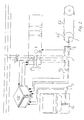
- FIGS. 1 a and 1 b are a side view and a top view, respectively, of an arrangement of a driving motor for a conveyance device feeding a converting press;
- FIG. 2 is a diagrammatic view of a control device for the driving motor and of FIGS. 1 a and 1 b;
- FIG. 3 shows a signal chart for cycle characteristics.
- FIGS. 1 a and 1 b show an independent motor/reductor unit 1 directly assembled with an extension of a transverse driving shaft 2 which comprises driving wheels 3 , 3 ′ of endless gripper bar chains 5 , 6 of a converting press.
- motor 1 is located at a unit 4 , which is shown to illustrate a prior art converting press arrangement including a mechanism for driving the gripper bar chains 5 , 6 and mechanical parts coupling the motor to the various actuated press stations.
- the parts for the mechanical drive are removed.
- This independent motor/reductor 1 can thus be assembled without modifying the embodiment of an existing machine.
- the independent motor/reductor 1 actuating the endless gripper bar chains 5 , 6 is preferably an electric motor of high dynamic regulation.
- This independent motor/reductor 1 can be selected from among synchronous motors, asynchronous motors, and d.c. motors, with or without a motor brake, as are commercially available.
- the inventors conducted tests using a brushless synchronous driving device comprising a motor type HXA60VH distributed by ABB Normelec S.A. (Switzerland) to drive the endless gripper bar chains 5 , 6 of a converting press.
- the conveyor and converting press were driven at significant rates, while the original mechanical driving means was removed.
- FIG. 2 shows the schematic diagram of the electronic control device of the independent motor/reductor 1 .
- the CDE control device receives from an absolute and incremental coder 9 a signal representing the exact location of a blanking platen 10 , this signal being used as a master reference within the whole system.
- the CDE control device also receives from an absolute and incremental coder 11 the absolute location of the gripper bar chains 5 , 6 .
- the CDE control device also receives the angular position of the independent motor/reductor 1 scanned by an absolute and incremental coder 12 .
- the comparison between these signals allows the electronic CDE control device to exactly define the engaging and releasing times of the independent motor/reductor 1 , i.e. to define the beginning and the end of the braking phase, and to issue the current/tension feeding instructions defining, at any time accelerations and speed rates for the independent motor/reductor 1 .
Abstract
An independent motor/reductor drives a conveyance device that feeds a converting press. The converting press includes a number of stations including a feeding station, a converting station, a waste stripping station and a delivery station. The conveyance device services the stations and includes two endless gripper bar chains to convey sheet material through the converting press. A transverse drive shaft drives the conveyance device under the control of the independent motor/reductor. The independent motor/reductor provides motion trajectories for the conveyance device that are independent of, but synchronized with, the serviced stations. The arrangement improves throughput, reduces machine wear and results in a simplified design.
Description
This is a divisional of U.S. patent application Ser. No. 10/057,064, filed Jan. 24, 2002 now U.S. Pat. No. 6,691,997 in the name of Mauro Chiari and Daniel Tapis and entitled INDEPENDENT DEVICE FOR SYNCHRONIZATION OF SHEET OPERATIONS AND CONVEYANCING.
The present invention relates to a device for sheet conveyance, into a converting press for paper or cardboard sheets comprising at least one feeding station, a converting station, a waste stripping station and a delivery station for converted sheets, said conveyance device including two endless gripper bar chains assembled for conveying the sheets from the feeding station to the delivery station, a transverse driving shaft equipped with driving wheels for the endless gripper bar chains and at least one device for sheet capture secured to the endless gripper bar chains.
The wording “transverse” here means a horizontal direction, perpendicular to the machine axis.
Concerning known converting presses, only one electric motor usually drives the whole machine. This motor directly actuates inertia flywheels, a clutch brake device being inserted between the flywheels and the other machine bodies. This system drives all elements functioning with synchronism, in particular the movable beam of the platen press, the waste stripping and blank delivering stations, as well as the chains bearing the gripper bars ensuring sheet capture and conveyance from one station to the next.
A sheet conveying and converting cycle includes a sheet stop phase during which a given sheet is conveyed to a converting operation, such as blanking or waste stripping, and at least one moving phase during which the sheet is conveyed from one station to the next. This moving phase necessarily includes an acceleration and a deceleration phase and, usually, between both, a phase during which the sheet moves at a constant speed.
Various embodiments carrying out this kind of cycle have been described, in which the wheels driving the chains are interdependent in rotation with a coupling unit. The coupling unit is alternately caught or released from a driving unit by axial displacement. Standby means release or immobilize the wheels driving the chains, although the driving unit is alternatively driven in one or another rotative direction.
Such mechanical devices were described for example with patents CH 219422 and CH 411555. For such devices, an oscillating toothed segment operates on the transverse driving shaft via a pinion. The toothed segment is actuated by a rod connected to an eccentric secured on the top of a shaft driven by the general machine driving device. A complete rotation of the machine driving device causes an entire back and forth run of the oscillating toothed segment.
This kind of mechanical drive deals with a single motion law, determined by the geometry of the parts. This kind of driving device is very suitable for low or average conveyor rates up to approximately 5,000-6,000 sheets/hour. Beyond these rates, accelerations and decelerations at the beginning and at the end of the motion phase become very strong. However, after the sheet blanking operation, the sheets are connected only by their nicks, which can break in the case of heavy acceleration, causing a machine jam.
Several mechanical devices have been proposed to overcome this defect. The patent CH 411555 suggests driving the toothed segment under the control of a double cam. One of the double cams sends a rocking motion to a lever which, by means of a connecting rod, drives the toothed segment. Another of the two lever elements cooperating with the two cams sends the back free motion to the toothed segment, and is elastically engaged against the cam. The cam system modifies the effect of the motion law by relieving the start-up forces. However, for a set of reference cams, the acceleration forces are relieved for a set range. If other ranges of operation concerning the motion are desired, the cams must be changed.
Another known device attempts to remove the time delay for the blanking operation. In one such device, the manufacturer provided two blanking station platens that travel together in linear motion with the blanked sheets. This solution removes the time delay involved in the blanking operation, while permitting modulation of the linear displacement motion of the endless gripper bar chains.
The aim of the present invention is to provide a device for sheet conveyance allowing high throughput rates while carrying out an optimal sheet conveying cycle without any overly strong accelerations that could potentially break the nicks between the sheets blanks. Another aim of the invention is to allow rate changes for the sheet conveying cycle, independently from the conveying cycle of the converting station. The rate modification of a sheet conveying cycle involves the conveyor acceleration and deceleration curves and the respective duration of a cycle phase according to the type of processing carried out. The rate of the sheet conveying cycle can be changed between different processing jobs without having to retool or change parts.
These aims are achieved by a sheet conveyance device according to the present invention. A sheet conveyance device far a converting press for paper or cardboard sheets is provided. The press comprises at least one feeding station, a converting station, a waste stripping station and a delivery station for converted sheets. The conveyance device includes two endless gripper bar chains arranged for conveying the sheets from the feeding station to the delivery station, a transverse driving shaft equipped with driving wheels for the endless gripper bar chains and at least one device for sheet capture secured to the endless gripper bar chains. The transverse driving shaft of the conveyance device is driven separately from the other press stations, by at least one independent motor. The independent motor can operate with driving cycles comprising at least one motion phase and one phase of deceleration and/or stops controlled by a control device. The duration of each independent motor driving cycle is equivalent to the duration of a converting cycle of said converting station.
The driving of the sheet conveyance device by a motor independent of the motor driving the other converting press stations was initially thought to be an inadequate model, because of the problem of proper synchronization between the sequential sheets and the blanking platen operation of the downstream stations. The inventors noted to the contrary that an appropriate command, particularly an electronic command, can properly synchronize the conveyor with a platen cycle. The drive command is synthesized from a representative signal for the blanking station platen location and a representative signal for the gripper bar chains location. The appropriately synthesized drive command can control the independent motor driving the gripper bar chains to run with optimal synchronism related to the platen cycle. During a conveying cycle, a control device driving the independent motor by delivering a suitable electrical current is able to adapt to changing demands and forces with much more flexibility than a mechanical device. The control device can vary the characteristics of the acceleration phase, of the deceleration phase and of the braking phase of the conveying device with greater consistency, simplicity and ease than a mechanical device, as well. The conveying by means of the independent motor in particular, permits better adjustment of the relative duration of the moving and braking phases of the gripper bar chains with respect to the moving and braking phases of the diecutting platen. Such an arrangement can decrease the duration of the platen braking phase, which permits an increased machine production rate.
Other characteristics and advantages will be apparent to one skilled in the art from the description of an embodiment of the invention, with reference to the drawings, in which:
The independent motor/reductor 1 actuating the endless gripper bar chains 5, 6 is preferably an electric motor of high dynamic regulation. This independent motor/reductor 1 can be selected from among synchronous motors, asynchronous motors, and d.c. motors, with or without a motor brake, as are commercially available. For example, the inventors conducted tests using a brushless synchronous driving device comprising a motor type HXA60VH distributed by ABB Normelec S.A. (Switzerland) to drive the endless gripper bar chains 5, 6 of a converting press. The conveyor and converting press were driven at significant rates, while the original mechanical driving means was removed. Several manufacturers offer electric motors with standard coupling embodiments able to withstand up to 200-500 Nm, permitting the gripper bar chains to reach accelerations up to 25 to 70 m/s2. The cost of such standard motors is lower than the cost of the equivalent mechanical elements of known devices.
Of note on these curves is the relationship between control tension and speed as well as the lack of excessive accelerations. By modifying the preset tension curve, one can easily remove the constant speed motion phase, or lengthen or shorten the motion phase duration in a given cycle.
Claims (6)
1. A method for operating a conveyor drive for a conveyor independently of a drive for a press station serviced by the conveyor, the method comprising:
generating a press station position signal related to an operating position of said press station;
providing said position signal to a motor controller for operating said conveyor drive;
computing a set of parameters defining a drive profile for operating said conveyor drive based on said position signal; and
applying said drive profile to said conveyor drive to operate said conveyor drive,
wherein said conveyor drive is operated in synchronization with said press station.
2. A method according to claim 1 , further comprising calculating at least one of a duration and amplitude of one or more of said drive profile parameters in relation to said position signal.
3. A method according to claim 2 , wherein said parameters defining said drive profile include acceleration, deceleration and braking.
4. A method according to claim 1 , further comprising:
generating a conveyor position signal related to an operating position of said conveyor;
providing said conveyor position signal to said motor controller for operating said conveyor drive; and
computing said drive profile for operating said conveyor drive based on said conveyor position signal and said press station position signal.
5. A method according to claim 1 , further comprising:
generating an angular position signal related to an operating position of said conveyor drive;
providing said angular position signal to said motor controller for operating said conveyor drive; and
computing said drive profile for operating said conveyor drive based on said angular position signal and said press station position signal.
6. A method for operating a conveyor drive for a conveyor independently of a drive for a press station serviced by the conveyor, the method comprising:
generating a press station position signal related to an operating position of said press station;
providing said position signal to a motor controller for operating said conveyor drive;
computing a set of parameters defining a drive profile for a complete operating cycle of said conveyor based on said position signal,
wherein said operating cycle comprises a moving phase in which a conveyed article is delivered to the press station by said conveyor, and a non-moving phase during which the conveyor pauses to permit an operation to be performed on the conveyed article by the press station; and
applying said drive profile to said conveyor drive to operate said conveyor drive,
wherein said conveyor drive is operated in synchronization with said press station.
Priority Applications (1)
| Application Number | Priority Date | Filing Date | Title |
|---|---|---|---|
| US10/645,138 US6845979B2 (en) | 2001-02-01 | 2003-08-21 | Independent device for synchronization of sheet operations and conveyancing |
Applications Claiming Priority (4)
| Application Number | Priority Date | Filing Date | Title |
|---|---|---|---|
| CH00179/01A CH694638A5 (en) | 2001-02-01 | 2001-02-01 | A sheet conveying device. |
| CH20010179/01 | 2001-02-01 | ||
| US10/057,064 US6691997B2 (en) | 2001-02-01 | 2002-01-24 | Independent device for synchronization of sheet operations and conveyancing |
| US10/645,138 US6845979B2 (en) | 2001-02-01 | 2003-08-21 | Independent device for synchronization of sheet operations and conveyancing |
Related Parent Applications (1)
| Application Number | Title | Priority Date | Filing Date |
|---|---|---|---|
| US10/057,064 Division US6691997B2 (en) | 2001-02-01 | 2002-01-24 | Independent device for synchronization of sheet operations and conveyancing |
Publications (2)
| Publication Number | Publication Date |
|---|---|
| US20040036209A1 US20040036209A1 (en) | 2004-02-26 |
| US6845979B2 true US6845979B2 (en) | 2005-01-25 |
Family
ID=4429080
Family Applications (2)
| Application Number | Title | Priority Date | Filing Date |
|---|---|---|---|
| US10/057,064 Expired - Lifetime US6691997B2 (en) | 2001-02-01 | 2002-01-24 | Independent device for synchronization of sheet operations and conveyancing |
| US10/645,138 Expired - Lifetime US6845979B2 (en) | 2001-02-01 | 2003-08-21 | Independent device for synchronization of sheet operations and conveyancing |
Family Applications Before (1)
| Application Number | Title | Priority Date | Filing Date |
|---|---|---|---|
| US10/057,064 Expired - Lifetime US6691997B2 (en) | 2001-02-01 | 2002-01-24 | Independent device for synchronization of sheet operations and conveyancing |
Country Status (13)
| Country | Link |
|---|---|
| US (2) | US6691997B2 (en) |
| EP (1) | EP1228994B1 (en) |
| JP (1) | JP3735072B2 (en) |
| KR (1) | KR100435248B1 (en) |
| CN (1) | CN1172835C (en) |
| AT (1) | ATE473939T1 (en) |
| AU (1) | AU1471402A (en) |
| BR (1) | BR0200270B1 (en) |
| CA (1) | CA2369940C (en) |
| CH (1) | CH694638A5 (en) |
| DE (1) | DE60236977D1 (en) |
| ES (1) | ES2348292T3 (en) |
| TW (1) | TW536519B (en) |
Cited By (2)
| Publication number | Priority date | Publication date | Assignee | Title |
|---|---|---|---|---|
| US20060197997A1 (en) * | 2005-03-02 | 2006-09-07 | Canon Kabushiki Kaisha | Image reading apparatus, and image expansion and contraction correcting method |
| US20130187333A1 (en) * | 2010-09-22 | 2013-07-25 | Ludovic Cuennet | Machine for processing elements in sheet form, comprising a chainset tensioner |
Families Citing this family (8)
| Publication number | Priority date | Publication date | Assignee | Title |
|---|---|---|---|---|
| CH694638A5 (en) * | 2001-02-01 | 2005-05-13 | Bobst Sa | A sheet conveying device. |
| DE10343460A1 (en) * | 2002-10-04 | 2004-04-15 | Saurer Gmbh & Co. Kg | Roller drive for synthetic fiber spinning uses individual frequency controlled motors with one motor operating at a controlled speed slip |
| JP2006079723A (en) * | 2004-09-09 | 2006-03-23 | Funai Electric Co Ltd | Optical disk device |
| DE102006049112A1 (en) | 2006-10-18 | 2008-04-30 | Heidelberger Druckmaschinen Ag | Flat bed-sheet punching machine |
| DE102012020360A1 (en) * | 2012-10-17 | 2014-04-17 | Heidelberger Druckmaschinen Ag | Punching machine with monitoring sensor and method for rapid shutdown of such a machine |
| RU2685898C1 (en) * | 2016-03-09 | 2019-04-23 | Бобст Мекс Са | Chain tensioner, machine for processing elements in form of sheets and method of tensioning chains |
| WO2019020203A1 (en) * | 2017-07-28 | 2019-01-31 | Hp Indigo B.V. | Printing system comprising a transport apparatus engaged with a track and method of printing |
| ES2795099B2 (en) * | 2020-05-07 | 2021-04-19 | Telesforo Gonzalez Maqu Slu | METHOD AND MACHINE FOR FORMING CARDBOARD BOXES BY GLUING, COMPUTER PROGRAM, AND COMPUTER-READABLE DEVICE THAT HAS STORED SAID PROGRAM |
Citations (11)
| Publication number | Priority date | Publication date | Assignee | Title |
|---|---|---|---|---|
| CH219422A (en) | 1941-04-26 | 1942-02-15 | Bobst Fils Sa J | Sheet-working machine. |
| US3184229A (en) | 1959-08-28 | 1965-05-18 | Samuel M Langston Co | Intermittent motion drive mechanism |
| CH411555A (en) | 1965-03-08 | 1966-04-15 | Bobst Fils Sa J | Machine working sheets |
| US4093904A (en) | 1976-02-04 | 1978-06-06 | Contraves Goerz Corporation | Multi-axis motion generator utilizing feedforward control |
| US4453436A (en) | 1980-09-03 | 1984-06-12 | Rengo Co., Ltd. | Die cutter and process for die cutting |
| US5348285A (en) | 1992-01-21 | 1994-09-20 | Blohm & Voss Ag | Hold-down device on handling machines, in particular punching machines, for thin, flat objects in particular sheets of paper |
| JPH07302103A (en) | 1994-04-30 | 1995-11-14 | Mitsubishi Electric Corp | Motion controller |
| US6345171B1 (en) * | 2000-07-11 | 2002-02-05 | Toshiba Tec Kabushiki Kaisha | Image forming apparatus and a method to control paper conveying speeds in image forming apparatus |
| US6370354B1 (en) * | 2000-08-08 | 2002-04-09 | Lexmark International, Inc. | Method and apparatus for controlling media-to-image registration of a single-pass intermediate transfer member-based printing apparatus |
| US6499397B2 (en) * | 2000-02-10 | 2002-12-31 | Bobst S.A. | Method of automatic register setting of printings in a rotary machine and device for working the method |
| US6691997B2 (en) * | 2001-02-01 | 2004-02-17 | Bobst Sa | Independent device for synchronization of sheet operations and conveyancing |
Family Cites Families (15)
| Publication number | Priority date | Publication date | Assignee | Title |
|---|---|---|---|---|
| US3042398A (en) * | 1954-06-15 | 1962-07-03 | S & S Corrugated Paper Mach | Sheet gripping means for cutting and creasing press |
| JPS58178137U (en) * | 1982-05-20 | 1983-11-29 | 株式会社リコー | Document feeder in copying machine |
| JPS58191156U (en) * | 1982-06-14 | 1983-12-19 | 株式会社リコー | Sheet conveyance device |
| JPS5971243A (en) * | 1982-10-18 | 1984-04-21 | Toshiba Corp | Uniform magnetic field generator |
| JPS6125340U (en) * | 1984-07-20 | 1986-02-15 | 三菱重工業株式会社 | Sheet feeding device |
| US4674739A (en) * | 1985-08-02 | 1987-06-23 | Corrugated Paper Machinery Corp. | Sheet transfer device |
| US5142323A (en) * | 1988-05-13 | 1992-08-25 | Ricoh Company, Ltd. | Paper feed control method for a copier |
| JPH03195661A (en) * | 1989-12-25 | 1991-08-27 | Mitsubishi Electric Corp | Sheet transport device |
| US5141221A (en) * | 1990-11-05 | 1992-08-25 | Heidelberg Harris Gmbh | Deceleration device in the folder of a rotary printing machine |
| DE69110274T2 (en) * | 1991-04-30 | 1995-10-19 | Hirakawa Kogyosha Kk | Roller device for conveying sheet-like materials. |
| EP0557609B1 (en) * | 1991-12-19 | 1997-03-12 | SYSTEM KURANDT GmbH | Apparatus for on line controlling of foldable box blanks |
| DE19640963A1 (en) * | 1996-10-04 | 1998-04-16 | Wolfgang Heiber | Preform feed mechanism for cartons |
| US5979316A (en) * | 1997-09-30 | 1999-11-09 | Corrugated Gear & Services, Inc. | Belt-driven printer-cutter machine for corrugated paperboard of varying thickness |
| CA2259785C (en) * | 1999-01-19 | 2008-07-29 | Peter E. Sandford | Jogger member, system and method for mounting jogger members and female and male blanking dies provided therewith |
| US6358191B1 (en) * | 1999-08-27 | 2002-03-19 | The Mead Corporation | System and method for flexible control and adjustment of a box forming machine |
-
2001
- 2001-02-01 CH CH00179/01A patent/CH694638A5/en not_active IP Right Cessation
- 2001-12-27 TW TW090132491A patent/TW536519B/en not_active IP Right Cessation
-
2002
- 2002-01-18 ES ES02001294T patent/ES2348292T3/en not_active Expired - Lifetime
- 2002-01-18 EP EP02001294A patent/EP1228994B1/en not_active Expired - Lifetime
- 2002-01-18 DE DE60236977T patent/DE60236977D1/en not_active Expired - Lifetime
- 2002-01-18 AT AT02001294T patent/ATE473939T1/en not_active IP Right Cessation
- 2002-01-22 CN CNB021028036A patent/CN1172835C/en not_active Expired - Lifetime
- 2002-01-24 US US10/057,064 patent/US6691997B2/en not_active Expired - Lifetime
- 2002-01-29 KR KR10-2002-0005033A patent/KR100435248B1/en active IP Right Grant
- 2002-01-30 AU AU14714/02A patent/AU1471402A/en not_active Abandoned
- 2002-01-31 BR BRPI0200270-1A patent/BR0200270B1/en not_active IP Right Cessation
- 2002-01-31 CA CA002369940A patent/CA2369940C/en not_active Expired - Fee Related
- 2002-02-01 JP JP2002025090A patent/JP3735072B2/en not_active Expired - Fee Related
-
2003
- 2003-08-21 US US10/645,138 patent/US6845979B2/en not_active Expired - Lifetime
Patent Citations (11)
| Publication number | Priority date | Publication date | Assignee | Title |
|---|---|---|---|---|
| CH219422A (en) | 1941-04-26 | 1942-02-15 | Bobst Fils Sa J | Sheet-working machine. |
| US3184229A (en) | 1959-08-28 | 1965-05-18 | Samuel M Langston Co | Intermittent motion drive mechanism |
| CH411555A (en) | 1965-03-08 | 1966-04-15 | Bobst Fils Sa J | Machine working sheets |
| US4093904A (en) | 1976-02-04 | 1978-06-06 | Contraves Goerz Corporation | Multi-axis motion generator utilizing feedforward control |
| US4453436A (en) | 1980-09-03 | 1984-06-12 | Rengo Co., Ltd. | Die cutter and process for die cutting |
| US5348285A (en) | 1992-01-21 | 1994-09-20 | Blohm & Voss Ag | Hold-down device on handling machines, in particular punching machines, for thin, flat objects in particular sheets of paper |
| JPH07302103A (en) | 1994-04-30 | 1995-11-14 | Mitsubishi Electric Corp | Motion controller |
| US6499397B2 (en) * | 2000-02-10 | 2002-12-31 | Bobst S.A. | Method of automatic register setting of printings in a rotary machine and device for working the method |
| US6345171B1 (en) * | 2000-07-11 | 2002-02-05 | Toshiba Tec Kabushiki Kaisha | Image forming apparatus and a method to control paper conveying speeds in image forming apparatus |
| US6370354B1 (en) * | 2000-08-08 | 2002-04-09 | Lexmark International, Inc. | Method and apparatus for controlling media-to-image registration of a single-pass intermediate transfer member-based printing apparatus |
| US6691997B2 (en) * | 2001-02-01 | 2004-02-17 | Bobst Sa | Independent device for synchronization of sheet operations and conveyancing |
Cited By (4)
| Publication number | Priority date | Publication date | Assignee | Title |
|---|---|---|---|---|
| US20060197997A1 (en) * | 2005-03-02 | 2006-09-07 | Canon Kabushiki Kaisha | Image reading apparatus, and image expansion and contraction correcting method |
| US7755812B2 (en) * | 2005-03-02 | 2010-07-13 | Canon Kabushiki Kaisha | Image reading apparatus, and image expansion and contraction correcting method |
| US20130187333A1 (en) * | 2010-09-22 | 2013-07-25 | Ludovic Cuennet | Machine for processing elements in sheet form, comprising a chainset tensioner |
| US9061845B2 (en) * | 2010-09-22 | 2015-06-23 | Bobst Mex Sa | Machine for processing elements in sheet form, comprising a chainset tensioner |
Also Published As
| Publication number | Publication date |
|---|---|
| CA2369940A1 (en) | 2002-08-01 |
| CN1369369A (en) | 2002-09-18 |
| ES2348292T3 (en) | 2010-12-02 |
| CN1172835C (en) | 2004-10-27 |
| KR100435248B1 (en) | 2004-06-11 |
| JP2002284419A (en) | 2002-10-03 |
| ATE473939T1 (en) | 2010-07-15 |
| US20020101028A1 (en) | 2002-08-01 |
| BR0200270A (en) | 2002-10-08 |
| EP1228994B1 (en) | 2010-07-14 |
| CH694638A5 (en) | 2005-05-13 |
| AU1471402A (en) | 2002-08-08 |
| BR0200270B1 (en) | 2010-06-01 |
| CA2369940C (en) | 2007-12-04 |
| JP3735072B2 (en) | 2006-01-11 |
| KR20020064171A (en) | 2002-08-07 |
| US20040036209A1 (en) | 2004-02-26 |
| DE60236977D1 (en) | 2010-08-26 |
| EP1228994A3 (en) | 2004-03-31 |
| TW536519B (en) | 2003-06-11 |
| EP1228994A2 (en) | 2002-08-07 |
| US6691997B2 (en) | 2004-02-17 |
Similar Documents
| Publication | Publication Date | Title |
|---|---|---|
| US6845979B2 (en) | Independent device for synchronization of sheet operations and conveyancing | |
| US20020014510A1 (en) | Gathering stapler with separate drives and method of operating the gathering stapler | |
| US10753434B2 (en) | Chain tensioner, machine for processing elements in the form of sheets and method for tensioning the chain sets | |
| US9327934B2 (en) | Sheet stacking apparatus and sheet stacking method | |
| US9969156B2 (en) | Transverse sheet withdrawal brake | |
| JP6159614B2 (en) | Electric servo press machine and its operating method | |
| CA2680042C (en) | Servo-driven forming press | |
| JP5748857B2 (en) | Sheet form element processing machine with chainset type tensioner | |
| US3822168A (en) | Drive system for bag machine | |
| CN108859243A (en) | A kind of automatic feeding of packing case and wear handle method and apparatus | |
| EP0329296B1 (en) | Dual feeding of sheets to processing machinery | |
| US9969155B2 (en) | Print sheet brake | |
| CN113287647B (en) | Cake placing machine | |
| US11485035B2 (en) | Sheet processing machine and method for driving at least one tool of a sheet processing machine | |
| CN2871386Y (en) | Automatic mould-cutting thermoprinting machine | |
| US3926355A (en) | Apparatus for intermittently feeding lengths of continuous sheet material at a constant velocity | |
| US20090136323A1 (en) | Device for transferring a case from a roll-down apparatus to a handover point | |
| CN104245555B (en) | Sheet folding apparatus | |
| JP2004010302A (en) | Paper feeding device in corrugated cardboard sheet carton manufacturing machine | |
| CN117416686A (en) | Device for producing adhesively bound printed matter with a transport system |
Legal Events
| Date | Code | Title | Description |
|---|---|---|---|
| STCF | Information on status: patent grant |
Free format text: PATENTED CASE |
|
| FPAY | Fee payment |
Year of fee payment: 4 |
|
| FPAY | Fee payment |
Year of fee payment: 8 |
|
| FPAY | Fee payment |
Year of fee payment: 12 |