EP1226746A1 - Porte-poignée pour tondeuse à buisson - Google Patents
Porte-poignée pour tondeuse à buisson Download PDFInfo
- Publication number
- EP1226746A1 EP1226746A1 EP02001491A EP02001491A EP1226746A1 EP 1226746 A1 EP1226746 A1 EP 1226746A1 EP 02001491 A EP02001491 A EP 02001491A EP 02001491 A EP02001491 A EP 02001491A EP 1226746 A1 EP1226746 A1 EP 1226746A1
- Authority
- EP
- European Patent Office
- Prior art keywords
- handle
- holding member
- operating pole
- groove
- operating
- Prior art date
- Legal status (The legal status is an assumption and is not a legal conclusion. Google has not performed a legal analysis and makes no representation as to the accuracy of the status listed.)
- Granted
Links
Images


Classifications
-
- A—HUMAN NECESSITIES
- A01—AGRICULTURE; FORESTRY; ANIMAL HUSBANDRY; HUNTING; TRAPPING; FISHING
- A01D—HARVESTING; MOWING
- A01D34/00—Mowers; Mowing apparatus of harvesters
- A01D34/01—Mowers; Mowing apparatus of harvesters characterised by features relating to the type of cutting apparatus
- A01D34/412—Mowers; Mowing apparatus of harvesters characterised by features relating to the type of cutting apparatus having rotating cutters
- A01D34/63—Mowers; Mowing apparatus of harvesters characterised by features relating to the type of cutting apparatus having rotating cutters having cutters rotating about a vertical axis
- A01D34/67—Mowers; Mowing apparatus of harvesters characterised by features relating to the type of cutting apparatus having rotating cutters having cutters rotating about a vertical axis hand-guided by a walking operator
- A01D34/68—Mowers; Mowing apparatus of harvesters characterised by features relating to the type of cutting apparatus having rotating cutters having cutters rotating about a vertical axis hand-guided by a walking operator with motor driven cutters or wheels
-
- A—HUMAN NECESSITIES
- A01—AGRICULTURE; FORESTRY; ANIMAL HUSBANDRY; HUNTING; TRAPPING; FISHING
- A01D—HARVESTING; MOWING
- A01D34/00—Mowers; Mowing apparatus of harvesters
- A01D34/835—Mowers; Mowing apparatus of harvesters specially adapted for particular purposes
- A01D34/90—Mowers; Mowing apparatus of harvesters specially adapted for particular purposes for carrying by the operator
-
- B—PERFORMING OPERATIONS; TRANSPORTING
- B25—HAND TOOLS; PORTABLE POWER-DRIVEN TOOLS; MANIPULATORS
- B25G—HANDLES FOR HAND IMPLEMENTS
- B25G3/00—Attaching handles to the implements
- B25G3/02—Socket, tang, or like fixings
- B25G3/12—Locking and securing devices
- B25G3/24—Locking and securing devices comprising clamping or contracting means acting transversely on the handle or socket
-
- Y—GENERAL TAGGING OF NEW TECHNOLOGICAL DEVELOPMENTS; GENERAL TAGGING OF CROSS-SECTIONAL TECHNOLOGIES SPANNING OVER SEVERAL SECTIONS OF THE IPC; TECHNICAL SUBJECTS COVERED BY FORMER USPC CROSS-REFERENCE ART COLLECTIONS [XRACs] AND DIGESTS
- Y10—TECHNICAL SUBJECTS COVERED BY FORMER USPC
- Y10T—TECHNICAL SUBJECTS COVERED BY FORMER US CLASSIFICATION
- Y10T403/00—Joints and connections
- Y10T403/70—Interfitted members
- Y10T403/7062—Clamped members
-
- Y—GENERAL TAGGING OF NEW TECHNOLOGICAL DEVELOPMENTS; GENERAL TAGGING OF CROSS-SECTIONAL TECHNOLOGIES SPANNING OVER SEVERAL SECTIONS OF THE IPC; TECHNICAL SUBJECTS COVERED BY FORMER USPC CROSS-REFERENCE ART COLLECTIONS [XRACs] AND DIGESTS
- Y10—TECHNICAL SUBJECTS COVERED BY FORMER USPC
- Y10T—TECHNICAL SUBJECTS COVERED BY FORMER US CLASSIFICATION
- Y10T74/00—Machine element or mechanism
- Y10T74/20—Control lever and linkage systems
- Y10T74/20576—Elements
- Y10T74/20732—Handles
- Y10T74/2078—Handle bars
- Y10T74/20792—Folding or adjustable
Definitions
- This invention relates to an improved handle holder for mounting handles to operating poles of bush cutting machines.
- Such kind of handle holder for bush cutting machines is disclosed, for example, in Japanese Utility Model Laid-Open Publication No. HEI-6-5699 entitled “Mounting Structure for Operating Handle of Bush Cutting Machine” or in Japanese Utility Model Laid-Open Publication No. HEI-1-32511 entitled “Handle Mounting Structure.”
- a bush cutting machine disclosed in HEI-6-5699 has an engine provided at a proximal end of an operating pole, a drive shaft contained in the operating pole and rotated by the engine, a cutter attached to a distal end of the operating pole and rotated by the drive shaft, and a U-Shaped handle mounted via a faster to the operating pole between the cutter and the engine.
- the operating pole In mounting the handle to the operating pole, the operating pole is first interposed and held between upper and lower fastening parts which constitute the faster. Then the base of the U-shaped handle is inserted into a receiving hole formed in the upper fastening part in a direction orthogonal to the operating pole. Thereafter fastening bolts are inserted from bolt holes formed in the upper fastening part into screw holes formed in the lower fastening part, being screwed into the screw holes for fastening, and thereby mounting the handle to the operating pole. In short, the operating pole and the handle are fastened to one another via the fastening bolts.
- a washer is slid into a slot which communicates with the receiving hole, extending the length of the receiving hole in the upper fastening part.
- the washer is formed with dislocation-preventing protrusions which are fitted into fitting portions formed in the base of the handle, thereby preventing the handle from rotating or slipping off.
- HEI-1-32511 discloses a handle mounting structure in which a bracket is first bolt fixed to an operating pole of a bush cutting machine. A lower bracket is attached to the bracket. The base of a U-shaped handle is interposed between an upper bracket and the lower bracket and fastened via fastening bolts. A hook and a protrusion, which constitute an engagement member, are provided to the upper and lower brackets, respectively, in a position opposite to the fastening bolts, and engaged with one another. Thus, the base of the handle is fastened between the upper and lower brackets via the engagement member and the fastening bolts, so that no unbalance occurs in fastening force, enabling the handle to be firmly mounted to the operating pole.
- the bracket to which the lower bracket is attached is attached to the operating pole via the bolt, and the fastening bolts are additionally used for mounting the handle.
- many bolts are used for mounting the handle to the operating pole, requiring much time for assemblage.
- a handle holder for fixing a handle to an operating pole of a bush cutting machine containing a drive shaft rotated by an engine driven, which comprises: a first holding member having an operating pole insertion hole for inserting the operating pole therethrough, a groove formed along the operating pole insertion hole, and a handle receiving groove orthogonal to the operating pole insertion hole, for covering substantially 1/2 of a total circumference of the handle; a second holding member having a wedge inserted into the groove, and a handle retaining groove arranged opposite to the handle receiving groove, for covering substantially 1/2 of the total circumference of the handle; and a plurality of bolts for connecting the first holding member and the second holding member; wherein, the first holding member is fixed to the operating pole with the wedge inserted into the groove, and the handle is interposed and fixed between the handle receiving groove of the first holding member and the handle retaining groove of the second holding member.
- the handle is fixed to the operating pole via the handle holder.
- the handle is interposed and held between the first holding member and the second holding member, and then the first and second holding members are fastened via the bolts.
- the operating pole and the handle holder are fixed with the wedge pressed into the groove, producing wedging effects.
- the second holding member is attached to the first holding member in a direction opposite to the engine toward the cutter.
- forward force also acts on the handle holder via the handle.
- the first and second holding members receive such force as to connect these members to one another via the wedge, so that only small pulling force acts on the bolts. This eliminates the need for a larger-diameter bolt for increased strength, enabling the bolts to be smaller in diameter, and thereby reducing the size of the handle holder.
- a bush cutting machine 10 has an operating pole 11 in a pipe shape, an engine 14 provided at a proximal end of the operating pole 11, and a cutter 16. in a disc shape provided at a distal end 15 of the operating pole 11.
- a drive shaft 12 is contained in the operating pole 11 and rotated by the engine driven. The rotation of the drive shaft 12 causes the cutter 16 to rotate.
- a handle 18 for operating the bush cutting machine 10 is fixed via a handle holder 19 to the operating pole 11 at a desired position (substantially in the middle in the figure) between the engine 14 and the cutter 16.
- the handle 18 is U-shaped as shown in FIG. 2.
- Reference numeral 21 denotes a hanging attachment for attaching a shoulder hanging belt.
- FIG. 2 shows the handle 18 fixed to the operating pole 11 via the handle holder 19.
- the handle 18 has a handle body 22 of a pipe or a bar, a left grip 24 at a left portion 23 of the body 22, and a controller 26 at a right portion 25.
- the controller 26 has a throttle lever 27 for controlling the number of revolutions of the engine 14.
- a wire (not shown) connected to the throttle lever 27 is extended through the handle holder 19 and the operating pole 11 and connected to the engine 14.
- the handle holder 19 consists of a separable first holding member 31 and second holding member 32 as shown in FIG. 3. These holding members 31, 32 are connected via four bolts 33.
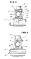
- the first holding member 31 has an operating pole insertion hole 35 through which the operating pole 11 is inserted, a groove 36 (See FIG. 4) formed along the insertion hole 35, and a handle receiving groove 38 orthogonal to the insertion hole 35, for covering substantially 1/2 of a total circumference 37 of the handle 18.
- the handle receiving groove 38 is arranged opposite to the cutter 16 (See FIG. 1).
- the first holding member 31 has a plurality of screw holes 39. The screw holes 39 receive the respective bolts 33.
- the second holding member 32 has a wedge 41 to be inserted into the groove 36 of the first holding member 31, and a handle retaining groove 42 arranged opposite to the handle receiving groove 38 of the first holding member 31, for covering substantially 1/2 of the total circumference 37 of the handle 18.
- Reference numeral 43 denotes through holes for inserting the respective bolts 33.
- Reference numeral 44 denotes a split surface.
- the wedge 41 has a wedge surface 45 as the upper surface and an operating pole abutting part 46 formed in the lower surface.
- FIG. 4 shows the first holding member 31 shown in FIG. 3.
- the groove 36 is formed in the first holding member 31 so as to extend along the operating pole insertion hole 35.
- Reference numeral 47 denotes a split surface.
- the insertion hole 35 has an operating pole receiving groove 52 for covering substantially 1/2 of a total circumference 51 of the operating pole 11.
- the groove 36 has an oblique surface 53 in a surface opposite to the receiving groove 52.
- the bolts 33 are inserted into the respective through holes 43 of the second holding member 32, and screwed into the screw holes 39 of the first holding member 31 so that the handle 18 is interposed and held between the handle receiving groove 38 of the first holding member 31 and the handle retaining groove 42 of the second holding member 32, thereby being fixed to the handle holder 19.
- the operating pole 11 is extended through the operating pole insertion hole 35, and the wedge 41 of the second holding member 32 is inserted into the groove 36 of the first holding member 31, whereby the first holding member 31 is fixed to the operating pole 11.
- FIGS. 7A and 7B a method of mounting the handle 18 to the operating pole 11 via the handle holder 19 will be described.
- the handle holder 19 used for assemblage consists of the first and second holding members 31, 32 and the four bolts 33, a significantly small number of components.
- the operating pole insertion hole 35 of the first holding member 31 is put and slid on the operating pole 11 as shown by arrow 1 ⁇ .
- the handle 18 is fitted into the handle receiving groove 38 formed in the first holding member 31 as shown by arrow 2 ⁇ , and is held by the handle retaining groove 42 of the second holding member 32 as shown by arrow 3 ⁇ .
- the wedge 41 of the second holding member 32 is fitted into the groove 36 of the first holding member 31, and the four bolts are screwed. That is, the first and second holding members 31, 32 are bolted to one another after the handle 18 is interposed therebetween.
- the operating pole 11 and the handle holder 19 are fixed to one another with the wedge 41 pressed into the groove 36, producing wedging effects. More specifically, with the plurality of bolts 33 screwed, the second holding member 32 is slid toward the first holding member (in the direction of arrow 4 ⁇ ) by axial force F (fastening force) of the bolts 33, and the wedge 41 of the second holding member 32 receives downward force from the oblique surface 53 of the first holding member 31. That is, the second holding member 32 is moved in the direction of arrow 5 ⁇ orthogonal to the operating pole 11, so that the operating pole abutting part 46 presses the operating pole 11, whereby the first and second holding members 31, 32 are fixed to the operating pole 11.
- the sliding second holding member 32 causes the handle retaining groove 42 to press the handle 18, thereby sandwiching and holding the handle 18 with the handle receiving groove 38.
- This structure eliminates a bolt used only for fixing the handle holder 19 to the operating pole 11. As a result, the number of bolts is reduced in half, reducing the cost of components and the number of assembling steps required.
- fixation of the handle holder 19 to the operating pole 11 and the fixation of the handle 18 can be simultaneously performed only with the plurality of bolts 33, which facilitates the mounting of the handle 18.
- production efficiency is improved.
- the plurality of bolts 33 serves both the fixation of the handle holder 19 to the operating pole 11 and the fixation of the handle 18, reducing the weight of the handle holder 19. In addition, this facilitates dissembling and reassembling of the structure, enhancing ease of assemblage and maintainability.
- the second holding member 32 opposing to the engine 14 shown in FIG. 1 is attached via the wedge 41 to the first holding member 31 in the direction of arrow 4 ⁇ .
- forward force also acts on the handle holder 19 via the handle 18.
- first and second holding members 31, 32 receive such force as to connect these members 31, 32 to one another via the wedge 41, only small pulling force acts on the plurality of bolts 33. This eliminates the need for a larger-diameter bolt for increasing the strength, enables the bolt to be smaller in diameter, thereby reducing the size of the handle holder.
- the handle holder has a first holding member (31) and a second holding member (32).
- the first holding member has an operating pole insertion hole (35) for insertion of the operating pole therethrough, an oblique groove (36), and a handle receiving groove (38) for receiving the base of the handle.
- the second holding member has a wedge (45) and a handle retaining groove (42). The wedge is fitted into the groove of the first holding member to fix the first holding member to the operating pole.
- the handle is interposed and held between the handle receiving groove of the first holding member and the handle retaining groove of the second holding member to be fixed to the first holding member.
Landscapes
- Life Sciences & Earth Sciences (AREA)
- Environmental Sciences (AREA)
- Harvester Elements (AREA)
- Sawing (AREA)
Applications Claiming Priority (2)
| Application Number | Priority Date | Filing Date | Title |
|---|---|---|---|
| JP2001015365A JP4341805B2 (ja) | 2001-01-24 | 2001-01-24 | 刈払機のハンドルホルダー構造 |
| JP2001015365 | 2001-01-24 |
Publications (2)
| Publication Number | Publication Date |
|---|---|
| EP1226746A1 true EP1226746A1 (fr) | 2002-07-31 |
| EP1226746B1 EP1226746B1 (fr) | 2004-11-10 |
Family
ID=18881929
Family Applications (1)
| Application Number | Title | Priority Date | Filing Date |
|---|---|---|---|
| EP02001491A Expired - Lifetime EP1226746B1 (fr) | 2001-01-24 | 2002-01-22 | Porte-poignée pour tondeuse à buisson |
Country Status (8)
| Country | Link |
|---|---|
| US (1) | US6618905B2 (fr) |
| EP (1) | EP1226746B1 (fr) |
| JP (1) | JP4341805B2 (fr) |
| KR (1) | KR100648484B1 (fr) |
| CN (1) | CN1258315C (fr) |
| CA (1) | CA2368863C (fr) |
| DE (1) | DE60201842T2 (fr) |
| TW (1) | TW513278B (fr) |
Cited By (3)
| Publication number | Priority date | Publication date | Assignee | Title |
|---|---|---|---|---|
| EP1530890A1 (fr) * | 2003-11-11 | 2005-05-18 | Active S.r.l. | Outil portable à manette amortie pour usage jardinier et agricole |
| EP2193704A1 (fr) * | 2008-12-03 | 2010-06-09 | Honda Motor Co., Ltd | Mécanisme de maintien de poignée de tuyau |
| DE10260466B4 (de) * | 2002-12-21 | 2014-07-03 | Andreas Stihl Ag & Co. Kg | Handgeführtes Arbeitsgerät |
Families Citing this family (15)
| Publication number | Priority date | Publication date | Assignee | Title |
|---|---|---|---|---|
| SE521651C2 (sv) * | 2001-02-15 | 2003-11-25 | Electrolux Ab | Anordning för infästning av handtag |
| US6840461B1 (en) * | 2003-10-03 | 2005-01-11 | Whitmire Micro-Gen Research Laboratories, Inc. | Adapter clamp for aerosol can |
| SE0401706D0 (sv) * | 2004-07-01 | 2004-07-01 | Electrolux Ab | Arrangement for securing a handle bar to a portable tool |
| US20060131083A1 (en) * | 2004-12-20 | 2006-06-22 | Matthys Hector M | Capped equalizer bar end joint |
| US7707766B2 (en) * | 2006-03-15 | 2010-05-04 | Millen Brian W | Device and method for casting |
| US7657972B2 (en) * | 2006-08-21 | 2010-02-09 | Graeme Reid Jenkins | Handle attachment assembly |
| ES1065270Y (es) * | 2007-04-04 | 2007-10-16 | Santos Jose Javier Sanchez | Mango ergonomico para herramientas tradicionales |
| US7789359B2 (en) * | 2007-04-24 | 2010-09-07 | Panduit Corp. | Auxiliary cable bracket |
| DE102008000293A1 (de) * | 2008-02-13 | 2009-08-20 | Hilti Aktiengesellschaft | Befestigungsvorrichtung für die Befestigung von plattenförmigen Elementen |
| US20110173778A1 (en) * | 2009-10-23 | 2011-07-21 | Michael Wales | Ergonomic auxiliary handle |
| KR101097268B1 (ko) * | 2010-03-03 | 2011-12-21 | 삼성에스디아이 주식회사 | 방열효율 및 장착구조가 개선된 배터리 팩 및 이를 포함하는 배터리 팩 조립체 |
| KR101192950B1 (ko) | 2011-04-19 | 2012-10-18 | 임병준 | 예초기 및 이에 적용되는 보호커버 |
| DE102013223821A1 (de) * | 2013-11-21 | 2015-05-21 | Robert Bosch Gmbh | Handwerkzeugmaschinenhandgriffvorrichtung |
| CA3027539C (fr) * | 2016-06-13 | 2024-04-30 | Hubbell Incorporated | Pince porte-charge pour transmettre des charges a un arbre |
| CN110140598B (zh) * | 2019-06-05 | 2021-09-24 | 苏州艾维科斯园林设备有限公司 | 一种耙草机用梳草刀 |
Citations (5)
| Publication number | Priority date | Publication date | Assignee | Title |
|---|---|---|---|---|
| US4282652A (en) * | 1977-05-13 | 1981-08-11 | Emerson Electric Co. | Apparatus for cutting vegetation |
| US5351565A (en) * | 1987-11-27 | 1994-10-04 | Komatsu Zenoah Kabushiki Kaisha | Engine starter |
| JPH08275646A (ja) * | 1995-04-07 | 1996-10-22 | Kioritz Corp | ハンドル取付機構 |
| US5740613A (en) * | 1995-08-02 | 1998-04-21 | Andreas Stihl | Trimming device with ergonomic handle bar |
| JPH119051A (ja) * | 1997-06-27 | 1999-01-19 | Honda Motor Co Ltd | 背負い式刈払機 |
Family Cites Families (13)
| Publication number | Priority date | Publication date | Assignee | Title |
|---|---|---|---|---|
| DE7706436U1 (de) * | 1977-03-02 | 1977-06-23 | Fa. Andreas Stihl, 7050 Waiblingen | Halterung fuer eine griffeinrichtung eines freischneidegeraetes |
| JPS6432511A (en) | 1987-07-28 | 1989-02-02 | Nec Corp | Agc amplifier circuit |
| US5167353A (en) * | 1990-03-27 | 1992-12-01 | Hughes Jack I | "U" post bracket for bicycles |
| JPH065699A (ja) | 1992-06-22 | 1994-01-14 | Kyocera Corp | 画像装置 |
| US5678458A (en) * | 1996-01-23 | 1997-10-21 | Kao; Yu-Ju | Joint structure for bicycle handlebar assembly |
| IT1288134B1 (it) * | 1996-05-30 | 1998-09-10 | Sasib Railway Electrification | Struttura composita e procedimento per il suo assiemaggio. |
| US5881606A (en) * | 1997-02-26 | 1999-03-16 | Trek Bicycle Corporation | Bicycle handlebar attachment device |
| DE19843157B4 (de) * | 1997-09-22 | 2009-01-22 | Kioritz Corp. | Motormaschine mit Sicherheitsmechanismus |
| US5970692A (en) * | 1997-10-06 | 1999-10-26 | Foster; Thomas E. | Clearing apparatus and carriage for a clearing device |
| US6305241B1 (en) * | 1999-06-28 | 2001-10-23 | Shimano, Inc. | Handlebar adapter for mounting a bicycle display |
| US6894812B1 (en) * | 2000-10-31 | 2005-05-17 | Hewlett-Packard Development Company, L.P. | Photosensor assembly with shared structures |
| TW492257B (en) * | 2000-11-04 | 2002-06-21 | Avision Inc | Control method of charge coupled device (CCD) detection module |
| US6608301B2 (en) * | 2001-07-31 | 2003-08-19 | Umax Data Systems, Inc. | Single step multi-section exposure scanning method |
-
2001
- 2001-01-24 JP JP2001015365A patent/JP4341805B2/ja not_active Expired - Fee Related
-
2002
- 2002-01-22 CA CA002368863A patent/CA2368863C/fr not_active Expired - Fee Related
- 2002-01-22 DE DE60201842T patent/DE60201842T2/de not_active Expired - Lifetime
- 2002-01-22 TW TW091100975A patent/TW513278B/zh not_active IP Right Cessation
- 2002-01-22 EP EP02001491A patent/EP1226746B1/fr not_active Expired - Lifetime
- 2002-01-23 US US10/055,286 patent/US6618905B2/en not_active Expired - Fee Related
- 2002-01-23 KR KR1020020003910A patent/KR100648484B1/ko not_active IP Right Cessation
- 2002-01-24 CN CNB021068364A patent/CN1258315C/zh not_active Expired - Fee Related
Patent Citations (5)
| Publication number | Priority date | Publication date | Assignee | Title |
|---|---|---|---|---|
| US4282652A (en) * | 1977-05-13 | 1981-08-11 | Emerson Electric Co. | Apparatus for cutting vegetation |
| US5351565A (en) * | 1987-11-27 | 1994-10-04 | Komatsu Zenoah Kabushiki Kaisha | Engine starter |
| JPH08275646A (ja) * | 1995-04-07 | 1996-10-22 | Kioritz Corp | ハンドル取付機構 |
| US5740613A (en) * | 1995-08-02 | 1998-04-21 | Andreas Stihl | Trimming device with ergonomic handle bar |
| JPH119051A (ja) * | 1997-06-27 | 1999-01-19 | Honda Motor Co Ltd | 背負い式刈払機 |
Non-Patent Citations (2)
| Title |
|---|
| PATENT ABSTRACTS OF JAPAN vol. 1997, no. 02 28 February 1997 (1997-02-28) * |
| PATENT ABSTRACTS OF JAPAN vol. 1999, no. 04 30 April 1999 (1999-04-30) * |
Cited By (3)
| Publication number | Priority date | Publication date | Assignee | Title |
|---|---|---|---|---|
| DE10260466B4 (de) * | 2002-12-21 | 2014-07-03 | Andreas Stihl Ag & Co. Kg | Handgeführtes Arbeitsgerät |
| EP1530890A1 (fr) * | 2003-11-11 | 2005-05-18 | Active S.r.l. | Outil portable à manette amortie pour usage jardinier et agricole |
| EP2193704A1 (fr) * | 2008-12-03 | 2010-06-09 | Honda Motor Co., Ltd | Mécanisme de maintien de poignée de tuyau |
Also Published As
| Publication number | Publication date |
|---|---|
| DE60201842D1 (de) | 2004-12-16 |
| CN1369192A (zh) | 2002-09-18 |
| DE60201842T2 (de) | 2005-03-31 |
| JP4341805B2 (ja) | 2009-10-14 |
| JP2002218813A (ja) | 2002-08-06 |
| US20020104193A1 (en) | 2002-08-08 |
| CN1258315C (zh) | 2006-06-07 |
| CA2368863A1 (fr) | 2002-07-24 |
| EP1226746B1 (fr) | 2004-11-10 |
| TW513278B (en) | 2002-12-11 |
| CA2368863C (fr) | 2006-05-16 |
| US6618905B2 (en) | 2003-09-16 |
| KR20020062837A (ko) | 2002-07-31 |
| KR100648484B1 (ko) | 2006-11-24 |
Similar Documents
| Publication | Publication Date | Title |
|---|---|---|
| EP1226746B1 (fr) | Porte-poignée pour tondeuse à buisson | |
| KR100849031B1 (ko) | 예초기 | |
| US4912848A (en) | Power tool handle | |
| US7073740B2 (en) | Motorized fishing reel actuating mechanism and rod assembly | |
| JP2001224215A (ja) | 駆動原動機を具備する作業機械 | |
| EP1102664B1 (fr) | Scie a decouper guidee a la main | |
| JP2002253024A (ja) | 刈払機 | |
| EP1102663B1 (fr) | Scie a chantourner manuelle dotee d'une surface d'appui clipsee de fa on amovible sur un plateau de sciage | |
| EP1201110B1 (fr) | Etrier support pour cultivateur | |
| JP7444461B2 (ja) | 連結工具、および、連結方法 | |
| JP4025534B2 (ja) | 枝打機 | |
| CN214023738U (zh) | 一种自行车配件加工用切割装置 | |
| CN103448037B (zh) | 一种后置动力工具 | |
| DE19925748A1 (de) | Handgeführte Laubsägemaschine | |
| JP3411473B2 (ja) | コンバイン | |
| CN213127032U (zh) | 一种多功能扶手架 | |
| US5305842A (en) | Feed device on a surface-cleaning machine | |
| JP3016184B2 (ja) | 二輪式両面裾刈機 | |
| JPH0621312Y2 (ja) | 茶畝の両面裾刈機 | |
| KR19980061370U (ko) | 예취기의 핸들 장착장치 | |
| JPH0755867Y2 (ja) | 小型エンジン作業機 | |
| JP3088083B2 (ja) | コンバインにおける刈取脱穀入切クラッチ | |
| US7052216B1 (en) | Work saver for an electric drill | |
| JP2561290B2 (ja) | 船外機のスロットルシャフト取付装置 | |
| CN117917303A (zh) | 作业机械以及设备用钩 |
Legal Events
| Date | Code | Title | Description |
|---|---|---|---|
| PUAI | Public reference made under article 153(3) epc to a published international application that has entered the european phase |
Free format text: ORIGINAL CODE: 0009012 |
|
| AK | Designated contracting states |
Kind code of ref document: A1 Designated state(s): AT BE CH CY DE DK ES FI FR GB GR IE IT LI LU MC NL PT SE TR |
|
| AX | Request for extension of the european patent |
Free format text: AL;LT;LV;MK;RO;SI |
|
| 17P | Request for examination filed |
Effective date: 20020814 |
|
| AKX | Designation fees paid |
Designated state(s): DE FR |
|
| GRAP | Despatch of communication of intention to grant a patent |
Free format text: ORIGINAL CODE: EPIDOSNIGR1 |
|
| GRAS | Grant fee paid |
Free format text: ORIGINAL CODE: EPIDOSNIGR3 |
|
| GRAA | (expected) grant |
Free format text: ORIGINAL CODE: 0009210 |
|
| AK | Designated contracting states |
Kind code of ref document: B1 Designated state(s): DE FR |
|
| REG | Reference to a national code |
Ref country code: IE Ref legal event code: FG4D |
|
| REF | Corresponds to: |
Ref document number: 60201842 Country of ref document: DE Date of ref document: 20041216 Kind code of ref document: P |
|
| PLBE | No opposition filed within time limit |
Free format text: ORIGINAL CODE: 0009261 |
|
| STAA | Information on the status of an ep patent application or granted ep patent |
Free format text: STATUS: NO OPPOSITION FILED WITHIN TIME LIMIT |
|
| ET | Fr: translation filed | ||
| 26N | No opposition filed |
Effective date: 20050811 |
|
| REG | Reference to a national code |
Ref country code: FR Ref legal event code: PLFP Year of fee payment: 14 |
|
| PGFP | Annual fee paid to national office [announced via postgrant information from national office to epo] |
Ref country code: DE Payment date: 20150113 Year of fee payment: 14 |
|
| PGFP | Annual fee paid to national office [announced via postgrant information from national office to epo] |
Ref country code: FR Payment date: 20150108 Year of fee payment: 14 |
|
| REG | Reference to a national code |
Ref country code: DE Ref legal event code: R119 Ref document number: 60201842 Country of ref document: DE |
|
| REG | Reference to a national code |
Ref country code: FR Ref legal event code: ST Effective date: 20160930 |
|
| PG25 | Lapsed in a contracting state [announced via postgrant information from national office to epo] |
Ref country code: DE Free format text: LAPSE BECAUSE OF NON-PAYMENT OF DUE FEES Effective date: 20160802 |
|
| PG25 | Lapsed in a contracting state [announced via postgrant information from national office to epo] |
Ref country code: FR Free format text: LAPSE BECAUSE OF NON-PAYMENT OF DUE FEES Effective date: 20160201 |