EP1225043A2 - Device for overturning flat sheets in half-turn revolving sheet-processing machines - Google Patents
Device for overturning flat sheets in half-turn revolving sheet-processing machines Download PDFInfo
- Publication number
- EP1225043A2 EP1225043A2 EP01128465A EP01128465A EP1225043A2 EP 1225043 A2 EP1225043 A2 EP 1225043A2 EP 01128465 A EP01128465 A EP 01128465A EP 01128465 A EP01128465 A EP 01128465A EP 1225043 A2 EP1225043 A2 EP 1225043A2
- Authority
- EP
- European Patent Office
- Prior art keywords
- sheet
- transfer drum
- gripper
- drum
- printing
- Prior art date
- Legal status (The legal status is an assumption and is not a legal conclusion. Google has not performed a legal analysis and makes no representation as to the accuracy of the status listed.)
- Withdrawn
Links
- 238000012545 processing Methods 0.000 title claims abstract description 10
- 238000012546 transfer Methods 0.000 claims abstract description 160
- 238000007639 printing Methods 0.000 claims abstract description 152
- 230000002441 reversible effect Effects 0.000 claims abstract description 44
- 238000003860 storage Methods 0.000 claims abstract description 21
- 239000000463 material Substances 0.000 claims description 46
- 230000008878 coupling Effects 0.000 claims description 8
- 238000010168 coupling process Methods 0.000 claims description 8
- 238000005859 coupling reaction Methods 0.000 claims description 8
- 238000013461 design Methods 0.000 description 11
- 239000000123 paper Substances 0.000 description 6
- 230000001133 acceleration Effects 0.000 description 4
- 239000000758 substrate Substances 0.000 description 4
- 230000000694 effects Effects 0.000 description 3
- 238000009434 installation Methods 0.000 description 3
- 238000004519 manufacturing process Methods 0.000 description 3
- 238000000034 method Methods 0.000 description 3
- 101100537937 Caenorhabditis elegans arc-1 gene Proteins 0.000 description 2
- 238000006243 chemical reaction Methods 0.000 description 2
- 239000003086 colorant Substances 0.000 description 2
- 238000010586 diagram Methods 0.000 description 2
- 230000002093 peripheral effect Effects 0.000 description 2
- 230000008569 process Effects 0.000 description 2
- 238000013459 approach Methods 0.000 description 1
- 238000005452 bending Methods 0.000 description 1
- 230000002146 bilateral effect Effects 0.000 description 1
- 230000005540 biological transmission Effects 0.000 description 1
- 230000008859 change Effects 0.000 description 1
- 238000007654 immersion Methods 0.000 description 1
- 238000012432 intermediate storage Methods 0.000 description 1
- 238000007645 offset printing Methods 0.000 description 1
- 230000002035 prolonged effect Effects 0.000 description 1
- 238000007493 shaping process Methods 0.000 description 1
- 230000001360 synchronised effect Effects 0.000 description 1
Images


Classifications
-
- B—PERFORMING OPERATIONS; TRANSPORTING
- B41—PRINTING; LINING MACHINES; TYPEWRITERS; STAMPS
- B41F—PRINTING MACHINES OR PRESSES
- B41F21/00—Devices for conveying sheets through printing apparatus or machines
- B41F21/10—Combinations of transfer drums and grippers
- B41F21/106—Combinations of transfer drums and grippers for reversing sheets, e.g. for perfecting machine
-
- Y—GENERAL TAGGING OF NEW TECHNOLOGICAL DEVELOPMENTS; GENERAL TAGGING OF CROSS-SECTIONAL TECHNOLOGIES SPANNING OVER SEVERAL SECTIONS OF THE IPC; TECHNICAL SUBJECTS COVERED BY FORMER USPC CROSS-REFERENCE ART COLLECTIONS [XRACs] AND DIGESTS
- Y10—TECHNICAL SUBJECTS COVERED BY FORMER USPC
- Y10S—TECHNICAL SUBJECTS COVERED BY FORMER USPC CROSS-REFERENCE ART COLLECTIONS [XRACs] AND DIGESTS
- Y10S271/00—Sheet feeding or delivering
- Y10S271/902—Reverse direction of sheet movement
Definitions
- the invention relates to a device for turning flat specimens in half-speed, sheet-processing machines, such as rotary printing machines.
- DE 37 10 257 A1 relates to a sheet-fed rotary printing press for the production of single-sided multi-color printing or perfecting.
- the transfer gap between the sheet transfer cylinder and the impression cylinder of the second printing unit compared to the normal gap width to the printing cylinder of the first Printing unit enlarged and the clear space from one to Detect the front or rear edge of the sheet from the circumference of the sheet transfer cylinder movable gripper system is bridged.
- DE 37 17 093 A1 also relates to a rotary printing machine for straight printing and Fine and reverse printing.
- a sheet transfer cylinder is arranged in the direction of travel of the sheet, with all of the cylinders Gripper systems are assigned.
- the sheet transfer cylinder is also safe to hand over even with thicker substrate
- Subordinate sheet support with essentially flat and approximately to Sheet transfer cylinder provided tangentially on the top of the support. To this the sheet transfer cylinder pushes the sheet as its approaches The trailing edge of the sheet holding the gripper with the free leading edge in front, whereby the Sheet from the sheet transfer cylinder with the sheet trailing edge from the top of the support is lifted off.
- DE 196 15 730 A1 relates to a turning device for a printing press, especially on a sheet-fed offset printing machine.
- the turning device for a printing press comprises one between a first impression cylinder and one second impression cylinder arranged transfer drum.
- a register cylinder with a plurality of suction openings sucking the sheets, which holds the sheet in register after opening the gripper device Promotes cache system.
- the bow is on a first one, with blow nozzles provided sheet guiding device in a substantially elongated form cached.
- a tongs reversing gripper device arranged on the transfer drum takes hold of the rear edge of the in the intermediate storage system filed sheet and passes this to a known, the subordinate Counter pressure cylinder formed gripper device, which is turned in this way Sheet is fed to a downstream printing nip for printing on the underside of the sheet.
- this can sheet material can also be stored on the impression cylinder.
- the sheet-like material is stored on the printing cylinder after printing, then gripped by the transfer drum gripper systems and turned.
- the half-turn machine concept i.e. the execution of the cylinders compared to Printing cylinder twice the circumference of the cylinder ends the printing process, i.e. the Sheets are printed out until the transfer of its leading edge to in straight printing mode the subsequent transfer drum takes place. For this reason, it is necessary to provide a complete sheet length between the printing point and the delivery center. Should a turn of the sheet material can be made below the printing cylinder to provide another sheet length space for storing the sheet.
- the invention is based on the object using a simultaneous gripper closure of the arcuate material To provide front and rear edges of a sheet turning device with the highest Accuracy works.
- the straight printing unit is identical.
- the sheet transport path is in the straight printing mode Rotary printing press outside of any required for sheet turning Components.
- the transport route for sheet material be it paper of any grammage or more rigid cardboard is in the perfecting mode of the Reversing printing unit on the opposite side of the one that functions as the transfer bow-guiding cylinder.
- the transfer drum for example in Face-print mode corresponds to the clockwise direction in face and reverse printing mode in operated in a counterclockwise direction of rotation and includes on both sides acting gripper systems, so that sheet material in one as the other Direction of rotation can be fixed on the transfer drum.
- the Turning / storage drum and an additional transport element outside the Transport path of the sheet material to the sheet-guiding cylinder in the Face print mode is essentially a sheet run through a pure Schönddruckwerk corresponding sheet passage, so that the reversing printing unit in Faceprint mode is printed with the same high quality standard as pure Beautifully printed works.
- the sheet material is transported in the perfecting mode on the side of the lateral surface of the transfer drum between the sheet leading Drums that face the sheet travel path in straight printing mode.
- the sheet transport path in the straight printing mode is strictly from Decouple the sheet transport path in the perfecting mode.
- the contour of the transfer drum in withdrawn with respect to the gripper systems recorded on the lateral surface thereof designed so that evasion and safe storage of the to be turned sheet material on the transfer drum ensured during the turn is.
- sheet-processing rotary printing machine can turn / storage drum as well an additionally arranged transport element only in the operating mode Drive perfecting while these components are in straight printing mode of the reversing printing unit can be stopped.
- This allows on the one hand Saving drive energy, on the other hand, pure straight printing becomes one Reverse printing unit configured according to the invention by for the beautiful / reverse printing mode required components are not affected.
- the transport path of the sheet material can be either Printing material in paper form of lighter or heavier grammages, be it printing material in Form of more rigid cardboard and its twist, over a first sheet-guiding Cylinder run, one opposite to the direction of rotation of the straight printing mode rotating transfer cylinder as well as a turning drum and the additional Transport unit, which can also be configured cylindrical, to the second arc-guiding cylinder.
- Another transport path in beautiful / reverse printing mode of the reversible printing unit proposed according to the invention can run the first sheet-guiding cylinder; also about a single-turn Transfer cylinder, and via opposite to the direction of rotation in straight printing mode rotating transfer drum to one in this variant as a turning drum functioning additional transport cylinder.
- the first sheet-guiding cylinder, the transfer drum and the second sheet-guiding cylinder preferably designed as a half-revving cylinder, i.e. in compared to Printing forme cylinder with double diameter.
- the transport element can be single-turn or in an integer divider in relation to the diameter of the printing form cylinder. This saves installation space and is in relation to the unprinted side of the sheet material uncritical, since no smearing can occur.
- Transfer drum effective bilateral gripper systems are included, which in one Design variant as a pliers gripper with an approximately 180 ° swivel movement able to execute. In addition to a 180 ° swivel movement
- the gripper systems which are effective on both sides, can be gripped on the Transfer drum also designed as a double gripper with two opposite one another, Form gripper arms that can be driven separately on a common axis.
- the gripper fingers of the double gripper each work with a separate gripper support surface together.
- the gripper system acting on both sides on the The outer surface of the transfer drum can also be operated as a curve-controlled, vertically up and down to form movable T-gripper, which is also two separate ones Gripper contact surfaces can be assigned.
- the vertical movement of the T-gripper on the outer surface of the transfer drum can be, for example, by a Realize lever transmission, its pivoting movement around a fixed bearing by means of a Rollers / cam drives can be generated.
- the gripper systems of the transfer drum proposed according to the invention in Reversible printing unit can be used to avoid collisions with others Machine components that can be activated in straight printing mode, i.e. extendable systems design as well as adjustable in a submerged position in the perfecting mode Train gripper systems.
- the gripper systems on the lateral surface of the Transfer drum as a whole can be moved into the lateral surface of the transfer drum be educated; finally it is also possible to move the gripper fingers around a swivel axis to be designed such that a folding movement describing a 180 ° circular arc is possible.
- the transfer drum and / or the additional transport element within the reversing printing unit can both on the Transfer drum as well as a conical support on the additional transport element be attached, with which in particular the side edges of more rigid Cardboard material can be supported.
- the conical contact surface having supporting element cooperating fall arresters can more rigid arcuate material on the contact surfaces of the conical support elements press to avoid excessive stretching and thus the risk of collision with the counteract the next arc stored on a cylinder.
- the catch hooks that can be activated are particularly on the rear edge of stiffer cardboard materials the radius of the cylinder, i.e. from one through that this substrate inherent bending stiffness brought about a stretched position in a wound position, i.e. on the lateral surface employed, slightly curved position.
- the inclined support surfaces having supporting element arrangement can be used both on the transfer drum become; in another embodiment variant, the additional transport element with installation space conditionally reduced diameter with such, the extended position more rigid material influencing device are provided.
- the second sheet-guiding cylinder is driven by a first gear train from which the gears of the turning drum or additional transport element are coupled out.
- the second sheet-guiding cylinder is driven via a parallel to the first Gear train lying gear train, in which the drive from the first sheet leading Cylinder, for example, via the gear wheel driving the turning drum to another, on the shaft of the transfer drum mounted gear and from this to the Gear of the additional transport element, which in turn is the drive wheel of the drives second sheet-guiding cylinder.
- All shafts of the cylinders listed are low-friction bearings in the side walls of the reversing printing unit.
- the conversion takes place in straight printing mode such that that for the back pressure components in a rest position of the turning drum and additional transport system and the transfer drum synchronized with the impression cylinder grippers directly coupled into the drive train becomes.
- the configuration of a reversing printing unit proposed according to the invention is preferably used on multi-color rotary presses, in which one - depending on Design variant of the sheet processing machine - number of pure Sheets and the reversing printing unit, in which pure Straight printing as well as reverse printing is possible, switched between them becomes. Thanks to the compatible cylinder diameter, it learns what is to be processed sheet material in straight printing mode in the configuration configured according to the invention Reverse printing unit a sheet guide, the sheet guide in pure printing units largely corresponds. By separating the transport routes of the arcuate Pure face printing mode from the path of the sheet material in the Fine / reverse printing mode in the reversing printing unit configured according to the invention mutual interference in the operating modes excluded.
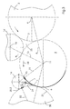
- FIG. 1 shows a first cylinder configuration reversible printing unit configured according to the invention with half-speed sheet-guiding Cylinders closer.
- FIG. 1 shows a first sheet-guiding cylinder 2, on the latter Shell surface 3 bends 1.
- the rear edge of the sheet 1 is designated 1.1, while the leading edge of the sheet is identified by reference number 1.2.
- the first sheet-guiding cylinder rotates about an axis of rotation 4, the sheet 1 with its Bottom 7 rests on the lateral surface 3 of the first sheet-guiding cylinder 2 and with its printed top 6, which can already be printed in four colors, one Assigning turning drum 14.
- the front edge 1.2 of the sheet 1 is one of the The lateral surface 3 of the gripper system 5 assigned to the first sheet-guiding cylinder 2 taken. 1 shows the individual states of the movement the sheet leading edge 1.2 when receiving the trailing edge 1.1 of the to be turned Sheet 1 by a turning gripper 15 on a single-turn turning drum 14 out closer.
- the sheet 1 is first on the lateral surface 3 of the first sheet-guiding cylinder 2 saved.
- the front edge 1.2 is in Gripper system 5 of the first sheet-guiding cylinder 2 through a transfer center 8 held out and transported to the position shown in Figure 1. With 15.0 it is Position of the sheet trailing edge 1.1 on the lateral surface 3 of the first sheet leading Cylinder 2 marked.
- the sheet 1 is gripped against the reference position of the leading edge 1.2, through which Gripper system 5 on the outer surface 3 of the first sheet-guiding cylinder 2 in this Gripper system stretched and aligned in register.
- Gripper system 5 On the outer surface 3 of the first sheet-guiding cylinder 2 in this Gripper system stretched and aligned in register.
- they are Sheet trailing edge 1.1 and sheet leading edge 1.2 each from a fixing system taken.
- 15.2 that is Trailing edge 1.1 of the aligned sheet from the suction element to the reversible gripper 15 Pass turning drum 14.
- the holding system 5 takes on the first sheet-guiding cylinder 2 its position 5.1, i.e. it opens to release the Front edge of sheet 1.2.
- the reversible gripper system 15 now transfers the rear edge 1.1 of the Sheet 1 in a position designated by 15.3.
- the front edge 1.2 of the sheet 1 remains continue on the outer surface 3 of the first sheet-guiding cylinder 2 (position 5.2).
- On a collision-free path 31 past the lateral surface 3 of the first sheet-guiding Cylinder 2 becomes the old rear edge 1.1 of the sheet, which is now the new one Represents the leading edge of the sheet, transferred to position 15.4.
- the new one Trailing edge 1.1 i.e. the old sheet leading edge 1.2 in position 5.3 below the open gripper system 5 on the lateral surface 3 of the first sheet-guiding cylinder 2 on.
- the reversing gripper 15 has the Turning drum 14, which rotates about the axis of rotation 16, an approximately 90 ° arc appropriate pivoting movement made. According to the rotational movement the turning drum 14 about its axis of rotation 16 reaches the old trailing edge 1.1 in the position marked with position symbol 15.5 under a further 90 ° Pivoting movement.
- the transfer drum 9 rotates as shown in Figure 1 against the Clockwise in direction 38 in the perfecting mode when turning sheet material 1.
- the on the outer surface of the transfer drum 9th recorded gripper systems 12 describe an envelope 10, the The outer surface of the transfer drum 11 itself is designed in a retracted contour can be to the reverse acceleration of the sheet material 1 during the Spread the phrase over an extended period of time.
- the transport route of the sheet 1 takes place through the theoretical gripper circuit 10, i.e. the envelope of the transfer drum 9 and one of these subordinate additional transport element 17 as a secant.
- the acceleration effects are much gentler, the mechanical ones Stresses, in particular the tendency of the sheet material to flutter, are significantly reduced.
- higher / higher printing can be done in the operating mode Achieve speeds.
- Gripped elements 32 on the circumference of the additional Transport element 17 is an approximately 90 ° deflection of the sheet 1 and Further funding in position 15.8.
- the old trailing edge 1.1 reaches the sheet Position 15.9, into which they are on a transfer center 22 between the axis of rotation 18 of the additional conveying element 17 and the axis of rotation of the not shown here second arc-guiding cylinder 20 arrives.
- the arc 1 Seized by this second arc-holding cylinder 20 received holding elements, the arc 1 is turned on the outer surface 21 of the second sheet-guiding cylinder.
- the outer surface 21 of the second sheet-guiding cylinder 20 now has the already printed upper side 6 to, while the still unprinted underside 7 of the sheet 1 faces outwards and in following pure straight printing units can be processed.
- the envelope 10 of the transfer drum 9 can act on both sides effective gripper systems, designated by reference numerals 12, 15, 25, 40, 44, 46 are recorded, which are described in more detail below.
- the transfer drum 9 can also be on the theoretical gripper circuit 10 collision-free in certain rotation ranges of the transfer drum 9 below the envelope curve 10 resettable gripper systems 12 that are either theoretical Gripper circuit 10 can be reset or can be folded by 180 °. These variants are also described in more detail below.
- Reference number 23 denotes a first gusset area, which is characterized by the Circumferential surfaces of the first sheet-guiding cylinder 2, the transfer drum 3 and the Circumferential surface of the turning drum 14 is formed.
- Another gusset area is with Reference numeral 24 denotes the one hand from the theoretical gripper circuit 10 of the Transfer drum 9 is limited and by the lateral surface 21 of the second arc-guiding cylinder 20 and finally from the envelope of the additional Transport element 17.
- the trailing edge 1.1 of the sheet 1, the bottom 7 of which on the lateral surface 3 of the first sheet-guiding cylinder 2 is only schematic here by means of one reproduced suction element in position 15.1 gripped and in a reversible gripper 15th the turning drum 14 transferred.
- the one that grips the rear edge 1.1 of the sheet 1 The reversing gripper guides the rear edge from the lateral surface 3 of the first sheet-guiding Cylinder 2 sheet to be removed in the positions 15.2, 15.3 and 15.4 and describes a collision-free path 31 receding behind the envelope of the turning drum.
- the trailing edge 1.1 of the sheet again has the envelope of the Turning drum 14 reached before in position 15.5 to the holding elements 12 on the theoretical gripper circuit 10 of the transfer drum 9 is transferred.
- the sheet 1 passes over a Transfer drum 14.1, rotating about axis of rotation 16, to a transfer drum 9.
- the transfer drum 9 rotates in the direction of rotation 38 counterclockwise Fine / reverse printing mode.
- Reference number 8 is the first transfer center between the axis of rotation 11 of the transfer drum 9 and the axis of rotation 4 of the first designated arc-guiding cylinder 2.
- a first gusset area 23 is formed by the Shell surface 3 of the first sheet-guiding cylinder 2 limited, on the other hand by theoretical gripper circle 10 of the transfer drum 9 and the outer surface of the Drum 14 '.
- the additional transport element 17 delimits a gusset area with its envelope curve 24, which further rotates counterclockwise from the lateral surface 21 second arc-guiding cylinder 20 is limited and on the other hand by the theoretical gripper circuit 10 of the transfer drum 9, which in the Schön- and Back pressure mode rotates in the direction of rotation 38.
- the old rear edge 1.1 of the sheet is opened the transfer center 19 between the axis of rotation 18 of the additional Transport element 17 and the axis of rotation 11 of the transfer drum 9 is formed.
- the Gripper system 32 of the additional transport element 17 grips the old rear edge 1.1 of the sheet, so that this between the movable gripper finger 32 and a support 36 is fixed.
- the gripper fingers 32 are around a fixed bearing 35 by means of a cam roller 33 moves, which in turn runs on the contour of a curve 34.
- Gripper pad 36 as well Fixed bearings 35, around which the gripper finger 32 pivots, are on the one Rotation axis 18 swinging arm 30 added.
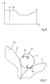
- the additional transport element 17 is a conical Support element 64 can be assigned, which one to be deflected by approximately 90 ° more rigid material serves as a support surface (see FIGS. 7 to 7.2).
- the transfer center 22 to reached second sheet-guiding cylinder 20 the sheet 1 is transferred with the old rear edge 1.1 on gripper systems, not shown here, on the lateral surface 21 of the second sheet-guiding cylinder 20 for further processing during the Pass through the printing units of the rotation.
- a half-speed configured transfer drum emerges from the representation according to 4.2 out, which acts as a turning drum according to this embodiment.
- the sheet 1 goes with its Top 6 to the outer surface 27 of a storage drum 26.
- the storage drum 26 is preferably of single-speed design and rotates about its axis of rotation 16.
- Holder devices 29 are provided, which the front edge 1.2 of the sheet on the Fix lateral surface 27.
- the clockwise rotating storage drum 26 stores the length of the sheet 1 with the leading edge 1.2 leading on the lateral surface 27, before a tong gripper 25 which can be pivoted through a 180 ° bend and which is based on the theoretical Gripper circle 10 of the transfer drum 9 obtained with the contour 9 withdrawn is provided, grips the rear edge 1.1 of the sheet 1.
- a tong gripper 25 which can be pivoted through a 180 ° bend and which is based on the theoretical Gripper circle 10 of the transfer drum 9 obtained with the contour 9 withdrawn is provided, grips the rear edge 1.1 of the sheet 1.
- the gripper element 25 gripped sheet 1 at the rear edge 1.1 of the Shell surface 27 of the storage drum 26.
- the gripper system designed as a gripper 25 Transfer drum 9 an approximately 180 ° comprising designated 28 Pivoting movement.
- Figures 5.1 to 5.5 are design variants of mutually effective Take out gripper systems.
- Figure 5.1 shows, for example, a pliers gripper 15, 25, 40, which on the withdrawn contour procured transfer drum 9 can be added.
- the tong gripper comprises gripper surfaces 43 and is pivotable about an axis 42.
- Figure 5.2 shows a gripper system that also acts on both sides, which is characterized by a Double gripper 44 is formed.
- the gripper fingers of the double gripper are on one common axis 42 added, with each gripper finger a separate Gripper pad 45 is assigned.
- FIG. 5.3 shows a T-gripper 46, which is also below the T-shaped crossbar two gripper pads 45 are assigned.
- the vertical extension and retraction of the tee of the T-gripper 46 is impressed on a hinged lever 47, which around a support 48 is pivotable.
- the pivoting movement of the lever 47 around the support 48 is initiated by a roller 49, the one on the contour here only schematically reproduced curve 50 rolls.
- FIG. 5.4 shows a holding element 12 on the transfer drum 9 which, in straight printing mode 59, extends its extended position by Pivots axis 42.
- the holding element 12 takes according to the illustration from FIG. 5.4, a submerged position 55.
- This will be Gripper system pivoted in toto around a support 48.
- the pivoting movement of the Gripper system, picked up on a lever 47, is actuated by a cam roller 49 impressed, which in turn runs on a curve contour 56.
- FIG. 5.5 An alternative solution to collision-free gripper guidance on the Transfer drum is through the design variant of a gripper system according to Figure 5.5 given.
- the gripper system is designed as a folding gripper, which is in straight printing mode 59 with a support 58 below the theoretical gripper circle 10 of the Transfer drum 9 cooperates.
- the folding gripper 57 is about the axis 42 pivotable and describes during its pivoting movement, i.e. his immersion below the theoretical gripper circle 10 an approximately 180 ° rotation, designated 28.
- the cylinder configuration shown only schematically in FIG. 6 from the first sheet-guiding cylinder 2, transfer drum 9, turning drum 14, additional Transport element 17 and second sheet-guiding cylinder 20 shows that at the Transfer drum 9 recorded gripper systems in straight printing mode 59 one Reference numerals 52 and 53, corresponding to the nominal diameter of the transfer drum 9 Describe the path.
- the perfecting mode 60 are those Transfer drum 9 assigned gripper systems to a gripper track 54, which recedes behind the theoretical gripper circuit 10, i.e. find the gripper systems reset behind the nominal diameter 52 of the transfer drum 9. So is one collision-free operation of the transfer drum as a sheet-guiding drum in the Fine print mode 59 guaranteed.
- a conical shape is shown in a schematic representation Support element more clearly, which both on the transfer drum and / or a additional transport element can be added.
- the additional transport element 17 or the transfer drum 9 is in side walls 61 or 62 of the invention configured reversing printing unit in the warehouse 69 added.
- the drive takes place on one Axis 63 via a gear provided on the drive side 61.
- the bevels 68 comprising conical support elements 64 are in relation to the transfer drum 9 or the additional transport element 17 is positioned such that it is a more rigid material 65 such as cardboard under the side area.
- catching device 66 are the Side edges of the more rigid box 65 to the inclined surfaces 68 of the conical Support elements 64 pressed so that the more rigid material 65 of an elongated, i.e. position protruding from the peripheral surface into one of the curvature of the peripheral surface of transfer drum 9 or additional transport element 17 corresponding Curvature can be transferred.
- Figure 7.1 shows the contact area of the catch element 66 with the lateral surfaces of the more rigid arcuate material 65 on an enlarged scale.
- the catch element 66 in the form of a hook undergoes a movement about a pivot axis Swivel movement 67, in which it moves from an open position 72 into a closed position Position 73 is transferred.
- Position 73 is transferred.
- the more rigid arcuate Material 65 by the employment of the catching element 66 from an extended position 70 in an approximately wound layer 71 is transferred. This creates the risk of collision rear area of the more rigid (cardboard) sheet material 65 with others machine components that are stationary.
- the contact surfaces 68 of the conical or conical support element 64 can be particularly preferably on a transfer drum 9 or on an additional transport element 17 in Take the shape of a transport cylinder.
- FIG. 8 shows a speed / time diagram of an additional one Transport element out closer.
- the sheet transfer is one Sheet, be it paper in heavier or lighter grammage or box 65.
- the sheet transfer speed is identified by reference numeral 82, the Circumferential speed of the arm 30 of the additional transport cylinder after the Sheet transfer 82 experiences a drop to shortly before the next sheet transfer 81 of the following copy, be it a sheet 1 of paper or a more rigid Printing material such as box 65, again at sheet transfer speed to be accelerated.
- the transport cylinder 17 has a very small diameter on its circumferential surface immersing in or exiting from this Gripper elements 32. These can be one behind the outer surface of the additional Transport element 17 withdrawn position 55 or can from the Step out of the outer surface of the transport cylinder 17 and thus from the transfer drum 9 take over arcuate material 1, 65 and to the lateral surface 21 of a second transfer bow-guiding cylinder 20. Accordingly, similar to the Transfer drum 9 behind the outer surface gripping elements 32 also on take up additional transport element 17 in the form of a transport cylinder.
- the gear trains go together Coupling element for driving the reversing printing unit configured according to the invention in straight printing mode as well as in straight printing and reverse printing mode.
- the gear train 102 in which the reversing printing unit configured according to the invention is located can be operated in the perfecting mode, is designated by reference number 102, while reference number 103 is in the pure printing operation of the reversing printing unit called setting course of the drive.
- the individual waves from the first sheet-guiding cylinder 2, turning drum, transfer drum, additional Transport element and second sheet-guiding cylinder are all in one Side wall 99 of the reversing printing unit with bearings shown only schematically here 91 rotatably added.
- an engaged state 97 as well as a reach disengaged state 98 On the shaft of the transfer drum 9 can for example one of the gear wheels 105 or 104 in the axial direction, designated by the Travel 96 are shifted so that the distance a to engage or out Engage, just corresponds to a gear width.
- the sleeve-shaped element 100 on the circumference of which the outer gear 105 of the shaft of the transfer drum 9 is fastened, returns to a dashed position 101 so that it is effectively disengaged of the gear 104 with the drive gears 90 and 92 of the first and second arc-guiding cylinder 1, 20 is ensured.
- This choice of drive wheels is used to switch from straight printing mode 59 to Fine and reverse printing mode 60 by coupling between direct and indirect Drive via turning drum 14 on the transfer drum 9 Rotation of the drive systems to one another such that the turning drum 14th depending on the format, exactly the end of the sheet 1, 65 lying on the printing cylinder detected.
- straight printing mode 59 the drive takes place in such a way that the gear wheels 93 and 94, that are required in the perfecting mode 60, in a rest position of Reversing drum 14 and additional transport element 17 are disengaged
Abstract
Die Erfindung bezieht sich auf eine Einrichtung zur Wendung von Bogen (1, 65) mit einer Übergabetrommel (9), die von zwei bogenführenden Zylindern (1, 20) begrenzt ist, der Übergabetrommel (9) eine Wende-/Speichertrommel (14, 26) sowie ein Transportelement (17) zugeordnet sind und die bogenverarbeitende Rotationsdruckmaschine im Schön- und Schön-/Widerdruckmodus (59, 60) betreibbar ist. Die Übergabetrommel (9) ist im Schönund im Schön-/Widerdruckmodus (59, 60) jeweils in entgegengesetzte Drehrichtungen (37, 38) antreibbar. An der Mantelfläche (10) der Übergabetrommel (9) sind in beide Drehrichtungen (37, 38) der Übergabetrommel (9) wirksame Greifersysteme (12; 15, 25, 40, 44, 46) aufgenommen. <IMAGE>The invention relates to a device for turning sheets (1, 65) with a transfer drum (9) which is delimited by two sheet-guiding cylinders (1, 20), the transfer drum (9) a turning / storage drum (14, 26 ) and a transport element (17) are assigned and the sheet-processing rotary printing press can be operated in the perfecting and perfecting modes (59, 60). The transfer drum (9) can be driven in opposite and opposite directions of rotation (37, 38) in the beautiful and reverse printing modes (59, 60). Effective gripper systems (12; 15, 25, 40, 44, 46) are accommodated on the lateral surface (10) of the transfer drum (9) in both directions of rotation (37, 38) of the transfer drum (9). <IMAGE>
Description
Die Erfindung bezieht sich auf eine Einrichtung zur Wendung flächiger Exemplare in halbtourigen, bogenverarbeitenden Maschinen, wie etwa Rotationsdruckmaschinen.The invention relates to a device for turning flat specimens in half-speed, sheet-processing machines, such as rotary printing machines.
DE 37 10 257 A1 bezieht sich auf eine Bogenrotationsdruckmaschine zur Herstellung von einseitigem Mehrfarbendruck oder Schön- und Widerdruck. In Laufrichtung des bogenförmigen Materials ist zwischen den Bogenzylinder zweier Druckwerke eine Bogenübergabetrommel aufgenommen, wobei gemäß dieses Lösungsvorschlags zur Erzielung einer insbesondere formatunabhängig arbeitenden Bauform vorgeschlagen wird, den Übergabespalt zwischen dem Bogenübergabezylinder und dem Druckzylinder des zweiten Druckwerkes gegenüber der normalen Spaltbreite zum Druckzylinder des ersten Druckwerkes vergrößert auszuführen und der lichte Zwischenraum von einem zum Erfassen der Bogenvorder- oder hinterkante aus dem Umfang des Bogenübergabezylinders herausbewegbaren Greifersystems überbrückt wird.DE 37 10 257 A1 relates to a sheet-fed rotary printing press for the production of single-sided multi-color printing or perfecting. In the direction of the sheet material is one between the sheet cylinders of two printing units Sheet transfer drum added, according to this proposed solution for Achieving a design that works in particular regardless of format is proposed, the transfer gap between the sheet transfer cylinder and the impression cylinder of the second printing unit compared to the normal gap width to the printing cylinder of the first Printing unit enlarged and the clear space from one to Detect the front or rear edge of the sheet from the circumference of the sheet transfer cylinder movable gripper system is bridged.
Auch DE 37 17 093 A1 bezieht sich auf eine Rotationsdruckmaschine für Schöndruck und
Schön- und Widerdruck. Zwischen den Druckzylindern zweier Druckwerke ist in
Laufrichtung des Bogens ein Bogenübergabezylinder angeordnet, wobei allen Zylindern
Greifersysteme zugeordnet sind. Zur Erzielung einer Bauform mit vergrößerter
Übergabesicher-heit auch bei dickerem Bedruckstoff ist ein dem Bogenübergabezylinder
nachgeordnetes Bogenauflager mit im wesentlichen flach gestalteter und etwa zum
Bogenübergabezylinder tangential liegender Auflageroberseite vorgesehen. Auf diese
schiebt der Bogenübergabezylinder den Bogen während der Annäherung seiner die
Bogenhinterkante haltenden Greifer mit der freien Bogenvorderkante voraus auf, wobei der
Bogen vom Bogenübergabezylinder mit der Bogenhinterkante von der Auflageroberseite
abgehoben wird.
Den oben skizzierten Lösungen haftet der Nachteil an, daß das bogenförmige Material mit der jeweils frisch bedruckten Seite notwendigerweise auf der Mantelfläche der Übergabetrommel (Speichertrommel) aufliegt und zur Erzielung einer registerhaltigen Wendung gespannt wird. Aus dieser unvermeidlichen Relativbewegung zwischen Trommelmantel und Bogen folgen Beschädigungen des Druckbildes.The solutions outlined above have the disadvantage that the sheet material with the respectively freshly printed side necessarily on the outer surface of the Transfer drum (storage drum) rests and to achieve a register Turn is tense. From this inevitable relative movement between Drum jacket and bow follow damage to the printed image.
DE 196 15 730 A1 bezieht sich auf eine Wendeeinrichtung für eine Druckmaschine, insbesondere auf eine Bogenrotations-Offsetdruckmaschine. Die Wendeeinrichtung für eine Druckmaschine umfaßt eine zwischen einem ersten Gegendruckzylinder und einem zweiten Gegendruckzylinder angeordnete Überführtrommel. Unterhalb dieser befindet sich ein Registerzylinder mit einer Vielzahl von den Bogen ansaugenden Saugöffnungen, welcher den Bogen nach Öffnung der Greifereinrichtung registerhaltig in ein Zwischenspeichersystem fördert. In diesem wird der Bogen auf einer ersten, mit Blasdüsen versehenen Bogenleiteinrichtung in im wesentlichen gestreckter Form zwischengespeichert. Eine an der Überführtrommel angeordnete Zangen-Wendegreifereinrichtung ergreift die Hinterkante des im Zwischenspeichersystem abgelegten Bogens und übergibt diese an eine bekannte, am nachgeordneten Gegendruckzylinder gebildete Greifereinrichtung, die den in dieser Weise gewendeten Bogen einem nachgeordneten Druckspalt zum Bedrucken der Bogenunterseite zuführt.DE 196 15 730 A1 relates to a turning device for a printing press, especially on a sheet-fed offset printing machine. The turning device for a printing press comprises one between a first impression cylinder and one second impression cylinder arranged transfer drum. Below is this a register cylinder with a plurality of suction openings sucking the sheets, which holds the sheet in register after opening the gripper device Promotes cache system. In this the bow is on a first one, with blow nozzles provided sheet guiding device in a substantially elongated form cached. A tongs reversing gripper device arranged on the transfer drum takes hold of the rear edge of the in the intermediate storage system filed sheet and passes this to a known, the subordinate Counter pressure cylinder formed gripper device, which is turned in this way Sheet is fed to a downstream printing nip for printing on the underside of the sheet.
Der Nachteil dieses Verfahrens ist der Umstand, daß nicht mit gleichzeitigem Greiferschluß an der Vorder- und Hinterkante des Bogens gearbeitet wird.The disadvantage of this method is the fact that not with simultaneous Gripper closure is worked on the front and rear edge of the sheet.
Neben den aus dem Stand der Technik skizzierten Lösungsmöglichkeiten kann das bogenförmige Material auch auf dem Druckzylinder gespeichert werden. Das bogenförmige Material wird nach dem Bedrucken auf dem Druckzylinder gespeichert, anschließend von Greifersystemen der Übergabetrommel erfaßt und gewendet. Beim halbtourigen Maschinenkonzept, d.h. der Ausführung der Zylinder im Vergleich zum Druckzylinder doppelt großen Zylinderumfang wird der Druckvorgang beendet, d.h. die Bogen werden ausgedruckt, bis im Schöndruckmodus die Übergabe seiner Vorderkante an die nachfolgende Übergabetrommel erfolgt. Aus diesem Grunde ist es erforderlich, zwischen Druckstelle und Übergabezentrale eine vollständige Bogenlänge vorzusehen. Soll eine Wendung des bogenförmigen Materials vorgenommen werden können, ist unterhalb des Druckzylinders eine weitere Bogenlänge Platz zum Speichern des Bogens vorzusehen. In addition to the possible solutions outlined in the prior art, this can sheet material can also be stored on the impression cylinder. The sheet-like material is stored on the printing cylinder after printing, then gripped by the transfer drum gripper systems and turned. At the half-turn machine concept, i.e. the execution of the cylinders compared to Printing cylinder twice the circumference of the cylinder ends the printing process, i.e. the Sheets are printed out until the transfer of its leading edge to in straight printing mode the subsequent transfer drum takes place. For this reason, it is necessary to provide a complete sheet length between the printing point and the delivery center. Should a turn of the sheet material can be made below the printing cylinder to provide another sheet length space for storing the sheet.
Aus dem Vorhalten einer weiteren Bogenlänge Platz unterhalb des Druckzylinders ergibt sich zwingend eine bestimmte Relativanordnung von Übertragungszylinder, d.h. Gummituchzylinder, Druckzylinder und Übergabetrommel relativ zueinander. Soll vor der Druckstelle noch der erforderliche Bauraum für die zur Sicherung der Druckqualität erforderlichen Bogenführungselemente verbleiben, erfordert dies einen großen Zylinderdurchmesser im Verhältnis zur maximalen Bedruckstofflänge. Damit einher gehen höhere Fertigungs- und Herstellkosten, größere dynamische Probleme aufgrund der höheren zu bewegenden Massen sowie insgesamt eine Zunahme der Länge von Druckmaschinen, die in Druckereien die ohnehin knappe Stellfläche belegen.The provision of a further sheet length results in space below the impression cylinder a certain relative arrangement of transfer cylinders, i.e. Blanket cylinder, impression cylinder and transfer drum relative to each other. Should before Printing site still the space required for ensuring the print quality required sheet guiding elements remain, this requires a large one Cylinder diameter in relation to the maximum substrate length. Go along with that higher manufacturing and manufacturing costs, greater dynamic problems due to the higher masses to be moved and an overall increase in length of Printing presses that occupy the already scarce footprint in print shops.
Allen aufgezeigten Lösungen ist die Tatsache gemeinsam, daß sie eine andere Gestaltung der Übergabetrommel im Wendedruckwerk erfordern, verglichen zur Gestaltung der Übergabetrommel in übrigen Druckwerken. Daraus entstehen nicht unerhebliche Probleme im Schöndruckmodus, in welchem eine Mehrfarbenrotationsdruckmaschine auch betrieben werden soll, insbesondere bei der Verarbeitung eines biegesteiferen Bedruckstoffes wie beispielsweise Karton.Common to all the solutions shown is the fact that they have a different design require the transfer drum in the reversing printing unit, compared to the design of the Transfer drum in other printing units. This creates not inconsiderable problems in straight printing mode, in which a multi-color rotary printing press is also operated should be, especially when processing a more rigid substrate such as for example cardboard.
Ausgehend vom skizzierten Stand der Technik liegt der Erfindung die Aufgabe zugrunde, unter Ausnutzung eines gleichzeitigen Greiferschlusses des bogenförmigen Materials an Vorder- und Hinterkante eine Bogenwendeeinrichtung bereitzustellen, die mit höchster Genauigkeit arbeitet.Starting from the outlined prior art, the invention is based on the object using a simultaneous gripper closure of the arcuate material To provide front and rear edges of a sheet turning device with the highest Accuracy works.
Erfindungsgemäß wird die Aufgabe durch die Merkmale des Patentanspruches 1 gelöst.According to the invention the object is solved by the features of
Die Vorteile der erfindungsgemäßen Lösung sind vor allem darin zu erblicken, daß die Formgebung des als Übergabetrommel füngierenden bogenführenden Zylinders im Wendedruckwerk mit derjenigen der Übergabetrommel in einem ausschließlichen Schöndruckwerk identisch ist. So liegt der Bogentransportweg im Schöndruckmodus der Rotationsdruckmaschine außerhalb jeglicher für die Bogenwendung erforderlicher Bauteile. Der Transportweg für bogenförmiges Material, sei es Papier jeglicher Grammatur oder auch biegesteiferen Karton liegt im Schön- und Widerdruckmodus des Wendedruckwerkes auf der gegenüberliegenden Seite des als Übergabe fungierenden bogenführenden Zylinders. Die Übergabetrommel, deren Drehrichtung beispielsweise im Schöndruckmodus dem Uhrzeigersinn entspricht wird im Schön- und Widerdruckmodus in einer dem Uhrzeigersinn entgegengesetzten Drehrichtung betrieben und umfaßt beidseitig wirkende Greifersysteme, so daß bogenförmiges Material in der einen wie der anderen Drehrichtung an der Übergabetrommel fixiert werden kann.The advantages of the solution according to the invention can be seen above all in that the Shaping of the sheet-guiding cylinder acting as a transfer drum in the Reverse printing unit with that of the transfer drum in an exclusive The straight printing unit is identical. For example, the sheet transport path is in the straight printing mode Rotary printing press outside of any required for sheet turning Components. The transport route for sheet material, be it paper of any grammage or more rigid cardboard is in the perfecting mode of the Reversing printing unit on the opposite side of the one that functions as the transfer bow-guiding cylinder. The transfer drum, the direction of rotation, for example in Face-print mode corresponds to the clockwise direction in face and reverse printing mode in operated in a counterclockwise direction of rotation and includes on both sides acting gripper systems, so that sheet material in one as the other Direction of rotation can be fixed on the transfer drum.
In weiterer Ausgestaltung des der Erfindung zugrundeliegenden Gedankens können die Wende-/Speichertrommel sowie ein zusätzliches Transportelement außerhalb des Transportpfades des bogenförmigen Materials an den bogenführenden Zylinder im Schöndruckmodus angeordnet werden. Damit ergibt sich auch im Wendedruckwerk im Schöndruckmodus der Rotation eine im wesentlichen dem Bogenlauf durch ein reines Schöndruckwerk entsprechende Bogenpassage, so daß das Wendedruckwerk im Schöndruckmodus mit demselben hohen Qualitätsstandard gedruckt wird wie reine Schöndruckwerke.In a further embodiment of the idea on which the invention is based, the Turning / storage drum and an additional transport element outside the Transport path of the sheet material to the sheet-guiding cylinder in the Face print mode. This also results in the reversing printing unit in Fine print mode of rotation is essentially a sheet run through a pure Schönddruckwerk corresponding sheet passage, so that the reversing printing unit in Faceprint mode is printed with the same high quality standard as pure Beautifully printed works.
Der Transportweg des bogenförmigen Materials im Schön- und Widerdruckmodus erfolgt auf der Seite der Mantelfläche der Übergabetrommel zwischen den bogenführenden Trommeln, die dem Transportweg des Bogens im Schöndruckmodus gegenüberliegt. Durch die Ausgestaltung der Übergabetrommel als ein in beide Drehrichtungen antreibbarer Zylinder läßt sich der Bogentransportpfad im Schöndruckmodus streng vom Bogentransportpfad im Schön-/Widerdruckmodus entkoppeln. Zur Erzielung eines kollisionsfreien Transportes auch biegesteiferen Bedruckstoffes durch das erfindungsgemäß konfigurierte Wendedruckwerk wird die Kontur der Übergabetrommel in bezug auf die an deren Mantelfläche aufgenommenen Greifersysteme zurückgenommen gestaltet, so daß ein Ausweichen sowie ein sicheres Speichern des zu wendenden bogenförmigen Materials an der Übergabetrommel während der Wendung sichergestellt ist.The sheet material is transported in the perfecting mode on the side of the lateral surface of the transfer drum between the sheet leading Drums that face the sheet travel path in straight printing mode. By designing the transfer drum as one in both directions of rotation drivable cylinder, the sheet transport path in the straight printing mode is strictly from Decouple the sheet transport path in the perfecting mode. To achieve a collision-free transport of even more rigid printing material through the configured according to the invention, the contour of the transfer drum in withdrawn with respect to the gripper systems recorded on the lateral surface thereof designed so that evasion and safe storage of the to be turned sheet material on the transfer drum ensured during the turn is.
Mit der erfindungsgemäß vorgeschlagenen Konfiguration eines Wendedruckwerkes einer bogenverarbeitenden Rotationsdruckmaschine lassen sich Wende-/Speichertrommel sowie ein zusätzlich angeordnetes Transportelement lediglich im Betriebsmodus Schön-/Widerdruck antreiben, während diese Komponenten im reinen Schöndruckbetrieb des Wendedruckwerkes stillgesetzt werden können. Dadurch läßt sich einerseits Antriebsenergie einsparen, andererseits wird der reine Schöndruckbetrieb eines erfindungsgemäß konfigurierten Wendedruckwerkes durch für den Schön/Widerdruckmodus erforderliche Komponenten nicht beeinflußt.With the configuration of a reversing printing unit proposed according to the invention sheet-processing rotary printing machine can turn / storage drum as well an additionally arranged transport element only in the operating mode Drive perfecting while these components are in straight printing mode of the reversing printing unit can be stopped. This allows on the one hand Saving drive energy, on the other hand, pure straight printing becomes one Reverse printing unit configured according to the invention by for the beautiful / reverse printing mode required components are not affected.
Im Schön-/Widerdruckmodus kann der Transportpfad des bogenförmigen Materials, sei es Bedruckstoff in Papierform leichterer oder schwererer Grammaturen, sei es Bedruckstoff in Form von biegesteiferem Karton und dessen Wendung, über einen ersten bogenführenden Zylinder verlaufen, einen entgegengesetzt zur Drehrichtung des Schöndruckmodus rotierenden Übergabezylinder sowie über eine Wendetrommel und die zusätzliche Transport-einheit, die ebenfalls zylinderförmig konfiguriert sein kann, an den zweiten bogenführenden Zylinder verlaufen. Ein weiterer Transportpfad im Schön/Widerdruckmodus des erfindungsgemäß vorgeschlagenen Wendedruckwerkes kann über den ersten bogenführenden Zylinder verlaufen; ferner über einen eintourigen Übergabezylinder, und über die entgegengesetzt zur Drehrichtung im Schöndruckmodus rotierende Übergabetrommel an einen in dieser Ausführungsvariante als Wendetrommel fungierenden zusätzlichen Transportzylinder vonstatten gehen. Überdies ist eine weitere Transportmöglichkeit des bogenförmigen Materials im Schön-/Widerdruckmodus durch den Transport des Bogens vom ersten bogenführenden Zylinder auf eine Speichertrommel gegeben, von dort auf eine als Wendetrommel fungierende Übergabetrommel, von dieser auf ein zusätzliches Transportelement, welches ebenfalls zylinderförmig konfiguriert sein kann, an die Mantelfläche des zweiten bogenführenden Zylinders.In the perfecting mode, the transport path of the sheet material can be either Printing material in paper form of lighter or heavier grammages, be it printing material in Form of more rigid cardboard and its twist, over a first sheet-guiding Cylinder run, one opposite to the direction of rotation of the straight printing mode rotating transfer cylinder as well as a turning drum and the additional Transport unit, which can also be configured cylindrical, to the second arc-guiding cylinder. Another transport path in beautiful / reverse printing mode of the reversible printing unit proposed according to the invention can run the first sheet-guiding cylinder; also about a single-turn Transfer cylinder, and via opposite to the direction of rotation in straight printing mode rotating transfer drum to one in this variant as a turning drum functioning additional transport cylinder. Furthermore, there is another one Possibility of transporting the sheet material in perfecting mode the transport of the sheet from the first sheet-guiding cylinder to a storage drum given, from there to a transfer drum functioning as a turning drum, from this on an additional transport element, which is also configured as a cylinder can, on the outer surface of the second sheet-guiding cylinder.
Um eine identische Führung des bogenförmigen Materials, sei es Papier leichterer und schwererer Grammaturen oder biegesteiferer Karton, durch die reinen Schöndruckwerke als auch das erfindungsgemäß konfigurierte Wendedruckwerk zu erzielen, werden der erste bogenführende Zylinder, die Übergabetrommel sowie der zweite bogenführende Zylinder bevorzugt als halbtourige Zylinder ausgeführt, d.h. in im Vergleich zum Druckformzylinder doppeltem Durchmesser.In order to guide the sheet material identically, be it lighter and paper heavier grammages or more rigid cardboard, due to the pure printing units and to achieve the reversing printing unit configured according to the invention, will be the first sheet-guiding cylinder, the transfer drum and the second sheet-guiding cylinder preferably designed as a half-revving cylinder, i.e. in compared to Printing forme cylinder with double diameter.
Wende-/Speichertrommel sowie das zusätzliche, ebenfalls zylinderförmig konfigurierte Transportelement lassen sich demgegenüber eintourig oder in einem ganzzahligen Teiler in bezug auf den Durchmesser des Druckformzylinders ausbilden. Dies spart Bauraum ein und ist in bezug auf die noch nicht bedruckte Seite des bogenförmigen Materials unkritisch, da keine Abschmiererscheinungen auftreten können.Turning / storage drum as well as the additional, also configured cylindrical In contrast, the transport element can be single-turn or in an integer divider in relation to the diameter of the printing form cylinder. This saves installation space and is in relation to the unprinted side of the sheet material uncritical, since no smearing can occur.
An der im Wendedruckwerk von zwei halbtourigen bogenführenden Zylindern begrenzten Übergabetrommel sind beidseitig wirksame Greifersysteme aufgenommen, welche in einer Ausgestaltungsvariante als Zangengreifer eine etwa 180° umfassende Schwenkbewegung auszuführen vermögen. Neben einem eine 180° Schwenkbewegung ausführenden Zangengreifer lassen sich die beidseitig wirksamen Greifersysteme an der Übergabetrommel auch als Doppelgreifer ausführen mit zwei einander gegenüberliegend, an einer gemeinsamen Achse getrennt antreibbaren Greiferarme ausbilden. Die Greiferfinger des Doppelgreifers arbeiten mit jeweils einer separaten Greiferauflagefläche zusammen. Daneben ist es denkbar, das beidseitig wirkende Greifersystem an der Mantelfläche der Übergabetrommel auch als kurvengesteuerten, vertikal auf und ab verschiebbaren T-Greifer auszubilden, dem ebenfalls zwei voneinander getrennte Greiferauflageflächen zugeordnet sein können. Die Vertikalbewegung des T-Greifers an der Mantelfläche der Übergabetrommel läßt sich beispielsweise durch eine Hebelübersetzung realisieren, deren Schwenkbewegung um ein Festlager mittels eines Rollen/Kurvenantriebes erzeugt werden kann.On the one bounded by two half-speed sheet-guiding cylinders in the reversing printing unit Transfer drum effective bilateral gripper systems are included, which in one Design variant as a pliers gripper with an approximately 180 ° swivel movement able to execute. In addition to a 180 ° swivel movement The gripper systems, which are effective on both sides, can be gripped on the Transfer drum also designed as a double gripper with two opposite one another, Form gripper arms that can be driven separately on a common axis. The The gripper fingers of the double gripper each work with a separate gripper support surface together. In addition, it is conceivable that the gripper system acting on both sides on the The outer surface of the transfer drum can also be operated as a curve-controlled, vertically up and down to form movable T-gripper, which is also two separate ones Gripper contact surfaces can be assigned. The vertical movement of the T-gripper on the outer surface of the transfer drum can be, for example, by a Realize lever transmission, its pivoting movement around a fixed bearing by means of a Rollers / cam drives can be generated.
Die Greifersysteme der erfindungsgemäß vorgeschlagenen Übergabetrommel im Wendedruckwerk lassen sich zur Vermeidung von Kollisionen mit anderen Maschinenkomponenten als im Schöndruckmodus aktivierbare, d.h. ausfahrbare Systeme gestalten sowie im Schön- und Widerdruckmodus in eine abgetauchte Position stellbare Greifersysteme ausbilden. Dazu können die Greifersysteme an der Mantelfläche der Übergabetrommel als Ganzes in die Mantelfläche der Übergabetrommel einfahrbar ausgebildet sein; schließlich ist es auch möglich, die Greiferfinger um eine Schwenkachse derart zu gestalten, daß eine einen 180° Kreisbogen beschreibende Klappbewegung möglich ist.The gripper systems of the transfer drum proposed according to the invention in Reversible printing unit can be used to avoid collisions with others Machine components that can be activated in straight printing mode, i.e. extendable systems design as well as adjustable in a submerged position in the perfecting mode Train gripper systems. For this purpose, the gripper systems on the lateral surface of the Transfer drum as a whole can be moved into the lateral surface of the transfer drum be educated; finally it is also possible to move the gripper fingers around a swivel axis to be designed such that a folding movement describing a 180 ° circular arc is possible.
Mit allen beschriebenen Greifersystemen kann eine Umkehrbeschleunigung des bogenförmigen Materials, sei es Papier, sei es biegesteiferer Karton über einen verlängerten Zeitraum hinweg erfolgen, da der Transportweg des bogenförmigen Materials kollisionsfrei durch den theoretischen Greiferkreis, d.h. der Hüllkurve der Übergabetrommel sowie des zusätzlichen Transportelementes als Sekante verläuft. Diese Führungsvariante des bogenförmigen Materials während der Wendung wohnt eine erheblich sanftere Beschleunigungswirkung inne; ein weiterer positiver Nebeneffekt dieser Führung des bogenförmigen Materials während der Wendung ist die Erzielung höherer Geschwindigkeiten im Schön- und Widerdruckmodus der mit dem erfindungsgemäß konfigurierten Wendedruckwerk ausgestatteten Mehrfarbenrotationsdruckmaschine. Die beschriebenen Greifersysteme tauchen in der kollisionsgefährdeten Lage zu den beiden Nachbarzylindern in die kreisförmige Kontur der Übergabetrommel ein.With all described gripper systems, a reverse acceleration of the sheet material, be it paper or be rigid cardboard over one prolonged period of time because of the transport route of the sheet material collision-free through the theoretical gripper circuit, i.e. the envelope of the Transfer drum and the additional transport element runs as a secant. This Guiding variant of the arched material during the turn resides in one considerably softer acceleration effect; another positive side effect of this Guiding the sheet material during the turn is achieving higher Speeds in the perfecting mode with that according to the invention configured multi-color rotary printing press. The Gripper systems described dive in the collision-prone position to the two Neighboring cylinders in the circular contour of the transfer drum.
In einer bevorzugten Ausgestaltungsvariante der Übergabetrommel und/oder des zusätzlichen Transportelementes innerhalb des Wendedruckwerkes kann sowohl an der Übergabetrommel als auch am zusätzlichen Transportelement eine konische Abstützung angebracht werden, mit welcher insbesondere die Seitenkanten von biegesteiferem Kartonmaterial abgestützt werden können. Mittels dem konische Auflageflächen aufweisenden Stützelement zusammenarbeitender Fangeinrichtungen läßt sich biegesteiferes bogenförmiges Material an die Kontaktflächen der konischen Stützelemente andrücken, um einer zu starken Streckung und damit der Kollisionsgefahr mit dem nächsten auf einem Zylinder gespeicherten Bogen entgegenzuwirken. Mittels der aktivierbaren Fanghaken wird insbesondere die Hinterkante steiferer Kartonmaterialien auf dem Radius des Zylinders gehalten, d.h. von einer durch die diesem Bedruckstoff innewohnenden Biegesteifigkeit bewirkten Strecklage in eine aufgewickelte Lage, d.h. an die Mantelfläche angestellte, leicht gekrümmte Lage verbracht. Die geneigte Stützflächen aufweisende Stützelementanordnung kann sowohl an der Übergabetrommel eingesetzt werden; in einer anderen Ausführungsvariante kann auf das zusätzliche Transportelement mit Bauraum bedingt verkleinertem Durchmesser mit einer solchen, die Strecklage biegesteiferen Materials beeinflussenden Einrichtung versehen werden.In a preferred embodiment variant of the transfer drum and / or the additional transport element within the reversing printing unit can both on the Transfer drum as well as a conical support on the additional transport element be attached, with which in particular the side edges of more rigid Cardboard material can be supported. By means of the conical contact surface having supporting element cooperating fall arresters can more rigid arcuate material on the contact surfaces of the conical support elements press to avoid excessive stretching and thus the risk of collision with the counteract the next arc stored on a cylinder. By means of the catch hooks that can be activated are particularly on the rear edge of stiffer cardboard materials the radius of the cylinder, i.e. from one through that this substrate inherent bending stiffness brought about a stretched position in a wound position, i.e. on the lateral surface employed, slightly curved position. The inclined support surfaces having supporting element arrangement can be used both on the transfer drum become; in another embodiment variant, the additional transport element with installation space conditionally reduced diameter with such, the extended position more rigid material influencing device are provided.
Am erfindungsgemäß konfigurierten Wendedruckwerk sind sowohl ein Räderzug für den Schöndruckmodus als auch ein Räderzug für den Schön-/Widerdruckmodus vorgesehen. Im Schöndruckmodus erfolgt der Antrieb des zweiten bogenführenden Zylinders über einen ersten Räderzug, aus welchem die Zahnräder der Wendetrommel bzw. des zusätzlichen Transportelementes ausgekoppelt sind. Im Schön- und Widerdruckmodus erfolgt der Antrieb des zweiten bogenführenden Zylinders über einen parallel zum ersten Räderzug liegenden Räderzug, in welchem der Antrieb vom ersten bogenführenden Zylinder beispielsweise über das die Wendetrommel antreibende Zahnrad an ein weiteres, auf der Welle der Übergabetrommel gelagertes Zahnrad übergeht und von diesem auf das Zahnrad des zusätzlichen Transportelementes, welches seinerseits das Antriebsrad des zweiten bogenführenden Zylinders antreibt. Sämtliche Wellen der aufgeführten Zylinder sind in Wälzlagern reibungsarm in den Seitenwänden des Wendedruckwerkes gelagert. Zur Umstellung der Räderzüge je nach gewähltem Betriebsmodus des Wendedruckwerkes ist in den Räderzug bevorzugt auf der Welle der Übergabetrommel ein Kupplungselement angeordnet, mit welchem die Umstellung von Schöndruckmodus auf Schön/Widerdruckmodus durch Kuppeln zwischen direktem und indirektem Antrieb über die Wendetrommel an der Übergabetrommel vorgenommen werden kann. Dabei ist sichergestellt, daß eine gleichzeitige Verdrehung der Antriebssysteme zueinander so erfolgt, daß die Wendetrommel formatabhängig genau das Ende des auf dem Druckzylinder liegenden Bogens erfaßt. Im Schöndruckmodus erfolgt die Umstellung derart, daß die für die Widerdruckkomponenten in einer Ruhestellung von Wendetrommel und zusätzlichem Transportsystem getrennt werden und die Übergabetrommel synchronisiert zu den Druckzylindergreifern direkt in den Antriebsstrang eingekuppelt wird.On the reversing printing unit configured according to the invention, there are both a gear train for the Fine print mode and a gear train for the perfecting mode are provided. In straight printing mode, the second sheet-guiding cylinder is driven by a first gear train from which the gears of the turning drum or additional transport element are coupled out. In perfect and reverse printing mode the second sheet-guiding cylinder is driven via a parallel to the first Gear train lying gear train, in which the drive from the first sheet leading Cylinder, for example, via the gear wheel driving the turning drum to another, on the shaft of the transfer drum mounted gear and from this to the Gear of the additional transport element, which in turn is the drive wheel of the drives second sheet-guiding cylinder. All shafts of the cylinders listed are low-friction bearings in the side walls of the reversing printing unit. to Change of the wheel trains depending on the selected operating mode of the reversing printing unit in the gear train preferably a coupling element on the shaft of the transfer drum arranged with which the conversion from face printing mode to beautiful / reverse printing mode by coupling between direct and indirect drive via the Reversing drum can be made on the transfer drum. It is ensures that a simultaneous rotation of the drive systems to each other so that the turning drum depends on the format exactly the end of the on the Printing cylinder lying sheet detected. The conversion takes place in straight printing mode such that that for the back pressure components in a rest position of the turning drum and additional transport system and the transfer drum synchronized with the impression cylinder grippers directly coupled into the drive train becomes.
Die erfindungsgemäß vorgeschlagene Konfiguration eines Wendedruckwerkes wird bevorzugt an Mehrfarbenrotationsdruckmaschinen eingesetzt, bei der eine - je nach Ausführungsvariante der bogenverarbeitenden Maschine - Anzahl von reinen Schöndruckwerken vorliegt und das Wendedruckwerk, in welchem reiner Schöndruckbetrieb sowie Schön-/Widerdruckbetrieb möglich ist, zwischen diese geschaltet wird. Dank der kompatibel ausgeführten Zylinderdurchmesser erfährt das zu verarbeitende bogenförmige Material im Schöndruckmodus im erfindungsgemäß konfigurierten Wendedruckwerk eine Bogenführung, die der Bogenführung in reinen Schöndruckwerken weitestgehend entspricht. Durch die Trennung der Transportwege des bogenförmigen Materials im reinen Schöndruckmodus vom Transportweg des bogenförmigen Materials im Schön-/Widerdruckmodus im erfindungsgemäß konfigurierten Wendedruckwerk sind gegenseitige Beeinflussungen in den Betriebsmodi ausgeschlossen.The configuration of a reversing printing unit proposed according to the invention is preferably used on multi-color rotary presses, in which one - depending on Design variant of the sheet processing machine - number of pure Sheets and the reversing printing unit, in which pure Straight printing as well as reverse printing is possible, switched between them becomes. Thanks to the compatible cylinder diameter, it learns what is to be processed sheet material in straight printing mode in the configuration configured according to the invention Reverse printing unit a sheet guide, the sheet guide in pure printing units largely corresponds. By separating the transport routes of the arcuate Pure face printing mode from the path of the sheet material in the Fine / reverse printing mode in the reversing printing unit configured according to the invention mutual interference in the operating modes excluded.
Im Schöndruckbetrieb erfolgt der Transport des nicht zu wendenden bogenförmigen Materials über eine optimierte Übergabetrommel, während bei Umschaltung auf Schön/Widerdruckmodus die für diesen Betriebsmodus am besten geeigneten Zylinderkomponenten zusammengeschaltet werden.In straight printing, the transport of the non-turning sheet takes place Material via an optimized transfer drum, while switching to beautiful / reverse printing mode the most suitable for this mode of operation Cylinder components are interconnected.
Anhand der Zeichnung wird die Erfindung nachstehend detaillierter erläutert.The invention is explained in more detail below with the aid of the drawing.
Es zeigt:
Figur 1- eine Zylinderkonfiguration eines erfindungsgemäßen Wendedruckwerkes mit halbtourigem bogenführenden Zylinder,
Figur 2- eine vergrößerte Darstellung eines Zylinderzwickelbereiches,
Figur 3- eine weitere Ausführungsvariante einer Zylinderkonfiguration mit halbtourigen Zylindern,
- Figur 4.1
- eine vergrößerte Darstellung eines zusätzlichen Transportelementes,
- Figur 4.2
- eine halbtourige, als Wendetrommel fungierende Übergabetrommel,
- Figuren 5.1 bis 5.5
- Ausführungsvarianten von beidseitig wirksamen Greifersystemen an der Übergabetrommel,
Figur 6- die sich im Schöndruckmodus und Schön-/Widerdruckmodus einstellenden Bahnen des Greifersystems am Umfang der Übergabetrommel,
Figur 7- die schematische Darstellung eines konischen Stützelementes an der Übergabetrommel und/oder eines zusätzlichen Transportelementes,
- Figuren 7.1, 7.2
- eine vergrößerte Darstellung eines Fangelementes in Vorder- und Seitenansicht,
Figur 8- ein Geschwindigkeits/Zeitdiagramm für das zusätzlich, beispielsweise zylinderförmig konfigurierte Transportelement,
Figur 9- die Darstellung eines zwischen dem zweiten bogenführenden Zylinder und der Übergabetrommel aufgenommenen zusätzlichen Transportelementes, ausgeführt in einem ganzzahligen Teiler des Durchmessers des Druckformzylinders und
Figur 10- die Räderzüge samt Kupplungselement zum Antrieb des erfindungsgemäß konfigurierten Wendedruckwerkes sowohl im reinen Schöndruckmodus als auch im Schön-/Widerdruckmodus.
- Figure 1
- a cylinder configuration of a reversible printing unit according to the invention with a half-speed sheet-guiding cylinder,
- Figure 2
- an enlarged view of a cylinder gusset area,
- Figure 3
- another embodiment variant of a cylinder configuration with half-speed cylinders,
- Figure 4.1
- an enlarged view of an additional transport element,
- Figure 4.2
- a half-speed transfer drum that functions as a turning drum,
- Figures 5.1 to 5.5
- Design variants of gripper systems effective on both sides on the transfer drum,
- Figure 6
- the webs of the gripper system that appear in the straight printing mode and the perfecting mode on the circumference of the transfer drum,
- Figure 7
- the schematic representation of a conical support element on the transfer drum and / or an additional transport element,
- Figures 7.1, 7.2
- an enlarged view of a catch element in front and side view,
- Figure 8
- a speed / time diagram for the additional, for example cylindrical, configured transport element,
- Figure 9
- the representation of an additional transport element received between the second sheet-guiding cylinder and the transfer drum, executed in an integer divisor of the diameter of the printing form cylinder and
- Figure 10
- the gear trains together with the coupling element for driving the reversible printing unit configured according to the invention both in the pure printing mode and in the perfecting mode.
Aus der Darstellung gemäß Figur 1 geht eine erste Zylinderkonfiguration eines erfindungsgemäß konfigurierten Wendedruckwerkes mit halbtourigen bogenführenden Zylindern näher hervor.1 shows a first cylinder configuration reversible printing unit configured according to the invention with half-speed sheet-guiding Cylinders closer.
Die Darstellung gemäß Figur 1 zeigt einen ersten bogenführenden Zylinder 2, an dessen
Mantelfläche 3 ein Bogen 1 anliegt. Die Hinterkante des Bogens 1 ist mit 1.1 bezeichnet,
während die Vorderkante des Bogens mit dem Bezugszeichen 1.2 identifiziert ist. Der erste
bogenführende Zylinder rotiert um eine Rotationsachse 4, wobei der Bogen 1 mit seiner
Unterseite 7 an der Mantelfläche 3 des ersten bogenführenden Zylinders 2 anliegt und mit
seiner bedruckten Oberseite 6, die bereits vierfarbig bedruckt sein kann, einer
Wendetrommel 14 zuweist. Die Vorderkante 1.2 des Bogens 1 ist von einem der
Mantelfläche 3 des ersten bogenführenden Zylinders 2 zugeordneten Greifersystem 5
ergriffen. Aus der Darstellung gemäß Figur 1 gehen die einzelnen Zustände der Bewegung
der Bogenvorderkante 1.2 bei der Aufnahme der Hinterkante 1.1 des zu wendenden
Bogens 1 durch einen Wendegreifer 15 an einer eintourig ausgebildeten Wendetrommel 14
näher hervor.The illustration according to FIG. 1 shows a first sheet-guiding
Der Bogen 1 wird zunächst auf der Mantelfläche 3 des ersten bogenführenden Zylinders 2
gespeichert. Um die Speicherung vornehmen zu können, wird die Vorderkante 1.2 im
Greifersystem 5 des ersten bogenführenden Zylinders 2 bis über eine Übergabezentrale 8
hinaus gehalten und bis in die in Figur 1 darstellte Lage transportiert. Mit 15.0 ist die
Position der Bogenhinterkante 1.1 auf der Mantelfläche 3 des ersten bogenführenden
Zylinders 2 gekennzeichnet. Zum Zeitpunkt 15.1 wird die Hinterkante 1.1 des Bogens 1
vom Wendegreifer 15 mittels eines hier nur schematisch dargestellten Saugelementes
erfaßt und von der Mantelfläche 3 des ersten bogenführenden Zylinders 2 abgehoben.
Danach wird der Bogen 1 gegen die Referenzlage der Vorderkante 1.2 ergriffen, durch das
Greifersystem 5 an der Mantelfläche 3 des ersten bogenführenden Zylinders 2 in diesem
Greifersystem gestreckt und registerhaltig ausgerichtet. In diesem Moment sind die
Bogenhinterkante 1.1 sowie Bogenvorderkante 1.2 jeweils von einem Fixierungssystem
ergriffen. In der mit 15.2 bezeichneten Position der Hinterkante 1.1 des Bogens 1 ist die
Hinterkante 1.1 des ausgerichteten Bogens vom Saugelement an den Wendegreifer 15 der
Wendetrommel 14 übergeben. Zu diesem Zeitpunkt nimmt das Haltesystem 5 am ersten
bogenführenden Zylinder 2 seine Position 5.1 ein, d.h. es öffnet zur Freigabe der
Bogenvorderkante 1.2. Das Wendegreifersystem 15 überführt nun die Hinterkante 1.1 des
Bogens 1 in eine mit 15.3 bezeichnete Lage. Die Vorderkante 1.2 des Bogens 1 verbleibt
weiter an der Mantelfläche 3 des ersten bogenführenden Zylinders 2 (Position 5.2). Auf
einer kollisionsfreien Bahn 31 vorbei an der Mantelfläche 3 des ersten bogenführenden
Zylinders 2 wird die alte Hinterkante 1.1 des Bogens, welche nunmehr die neue
Bogenvorderkante darstellt, in Position 15.4 überführt. Zu diesem Zeitpunkt liegt die neue
Bogenhinterkante 1.1, d.h. die alte Bogenvorderkante 1.2 in Position 5.3 unterhalb des
geöffneten Greifersystems 5 an der Mantelfläche 3 des ersten bogenführenden Zylinders 2
an. In der mit Bezugszeichen 15.4 bezeichneten Position hat der Wendegreifer 15 der
Wendetrommel 14, die um die Rotationsachse 16 rotiert, eine ca. einem 90° Bogen
entsprechende Schwenkbewegung vorgenommen. Entsprechend der Rotationsbewegung
der Wendetrommel 14 um ihre Rotationsachse 16 gelangt die alte Bogenhinterkante 1.1 in
die mit Positionszeichen 15.5 bezeichnete Position unter einer weiteren 90°
Schwenkbewegung. Von der mit 15.3 bezeichneten Position der Bogenhinterkante bis zur
mit Position 15.5 bezeichneten Position der alten Bogenhinterkante 1.1 hat der an der
Umfangsfläche auf einer kollisionsfreien Bahn 31 geführte Wendegreifer eine 180°-Schwenkbewegung
vollzogen und liegt nun in der Übergabezentrale 13, die zwischen
Rotationsachse 11 einer Übergabetrommel 9 der Rotationsachse 16 der Wendetrommel 14
gebildet ist. Zu diesem Zeitpunkt liegt die Unterseite 7 des Bogens 1 nach außen weisend,
während die bedruckte Oberseite, die beispielsweise zwei-, drei- oder vierfarbig bedruckt
und veredelt sein kann, der Rotationsachse 11 der Übergabetrommel 9 zuweist.The
Die Übergabetrommel 9 rotiert gemäß der Darstellung in Figur 1 entgegen des
Uhrzeigersinns in Richtung 38 im Schön- und Widerdruckmodus bei der Wendung
bogenförmigen Materials 1. Die an der Mantelfläche der Übergabetrommel 9
aufgenommenen Greifersysteme 12 beschreiben eine Hüllkurve 10, wobei die
Mantelfläche der Übergabetrommel 11 selbst in zurückgenommener Kontur ausgebildet
sein kann, um die Umkehrbeschleunigung des bogenförmigen Materials 1 während der
Wendung über einen verlängerten Zeitraum zu verteilen. Der Transportweg des Bogens 1
erfolgt durch den theoretischen Greiferkreis 10, d.h. die Hüllkurve der Übergabetrommel 9
und eines dieser nachgeordneten zusätzlichen Transportelements 17 als Sekante. Dadurch
sind die Beschleunigungswirkungen wesentlich sanfter, die mechanischen
Beanspruchungen, insbesondere die Flatterneigung des bogenförmigen Materials, werden
erheblich herabgesetzt. Ferner lassen sich im Betriebsmodus Schön-/Widerdruck höhere
Geschwindigkeiten erzielen.The
An der mit zurückgenommener Kontur beschaffenen Übergabetrommel wird das
bogenförmige Material 1 von einem Halteelement 12 ergriffen und in Position 15.6
gefördert. Mit Position 15.6 ist die vorlaufende Kante, d.h. die alte Hinterkante 1.1 des
Bogens 1, ergriffen durch das Halteelement 12, identifiziert. Der sich an die Einspannstelle
des Bogens 1 anschließende Bereich ragt in die Hüllkurve 11, d.h. den theoretischen
Greiferkreis der Übergabetrommel 9 hinein. Von Position 15.6 wird die alte
Bogenhinterkante 1.1 des Bogens in Position 15.7 gefördert, in welcher sie auf einer
Übergabezentrale 19 liegt. Die Übergabezentrale 19 wird zwischen der Rotationsachse 11
der Übergabezentrale und der Rotationsachse 18 eines zusätzlichen Transportelementes 17
gebildet. Ergriffen von Greif-elementen 32 am Umfang des zusätzlichen
Transportelementes 17 erfolgt eine ca. 90° Umlenkung des Bogens 1 und eine
Weiterförderung in Position 15.8. Schließlich erreicht die alte Hinterkante 1.1 des Bogens
Position 15.9, in welche sie auf einer Übergabezentrale 22 zwischen der Rotationsachse 18
des zusätzlichen Förderelementes 17 und der hier nicht dargestellten Rotationsachse des
zweiten bogenführenden Zylinders 20 gelangt. Ergriffen von an diesem zweiten
bogenführenden Zylinder 20 aufgenommenen Halteelementen liegt der Bogen 1 gewendet
auf der Mantelfläche 21 des zweiten bogenführenden Zylinders auf. Der Mantelfläche 21
des zweiten bogenführenden Zylinders 20 weist nunmehr die bereits bedruckte Oberseite 6
zu, während die noch unbedruckte Unterseite 7 des Bogens 1 nach außen weist und in
nachfolgenden reinen Schöndruckwerken bearbeitet werden kann.This is done on the transfer drum, which has a retracted
Am Umfang des theoretischen Greiferkreises, d.h. der Hüllkurve 10 der Übergabetrommel
9 können beidseitig wirksame Greifersysteme, bezeichnet mit Bezugszeichen 12, 15, 25,
40, 44, 46 aufgenommen werden, die nachfolgend noch eingehender beschrieben werden.
Daneben lassen sich auf dem theoretischen Greiferkreis 10 der Übergabetrommel 9 auch
kollisionsfrei in bestimmten Drehbereichen der Übergabetrommel 9 unter die Hüllkurve 10
zurückstellbare Greifersysteme 12 aufnehmen, die entweder unter den theoretischen
Greiferkreis 10 zurückgestellt werden können oder um 180° geklappt werden können.
Auch diese Ausführungsvarianten werden nachfolgend eingehender beschrieben.On the scope of the theoretical gripper circle, i.e. the
Mit Bezugszeichen 23 ist ein erster Zwickelbereich bezeichnet, der durch die
Umfangsflächen des ersten bogenführenden Zylinders 2, der Übergabetrommel 3 und die
Umfangsfläche der Wendetrommel 14 gebildet wird. Ein weiterer Zwickelbereich ist mit
Bezugszeichen 24 bezeichnet, der einerseits von dem theoretischen Greiferkreis 10 der
Übergabetrommel 9 begrenzt ist sowie von der Mantelfläche 21 des zweiten
bogenführenden Zylinders 20 und schließlich von der Hüllkurve des zusätzlichen
Transportelementes 17.
Aus der Darstellung gemäß Figur 2 geht eine vergrößerte Wiedergabe eines ersten Zylinderzwickelbereiches näher hervor. An enlarged representation of a first is shown in the illustration according to FIG Cylinder gusset area.
Die Bogenhinterkante 1.1 des Bogens 1, der mit seiner Unterseite 7 an der Mantelfläche 3
des ersten bogenführenden Zylinders 2 anliegt, wird mittels eines hier nur schematisch
wiedergegebenen Saugelementes in Position 15.1 ergriffen und in einen Wendegreifer 15
der Wendetrommel 14 überführt. Der die Hinterkante 1.1 des Bogens 1 erfassende
Wendegreifer führt die Hinterkante von der Mantelfläche 3 des ersten bogenführenden
Zylinders 2 abzunehmenden Bogens in die Position 15.2, 15.3 sowie 15.4 und beschreibt
dabei eine hinter die Hüllkurve der Wendetrommel zurücktretende kollisionsfreie Bahn 31.
In Position 15.4 hat die Hinterkante 1.1 des Bogens wieder die Hüllkurve der
Wendetrommel 14 erreicht, bevor sie in Position 15.5 an die Halteelemente 12 auf dem
theoretischen Greiferkreis 10 der Übergabetrommel 9 überführt wird. Im in Figur 2
dargestellten Zustand rotiert die Übergabetrommel in Drehrichtung 38, d.h. der
Drehrichtung, die für einen Schön-/Widerdruckmodus 60 maßgeblich ist. Das
Halteelement 12, welches die Hinterkante 1.1 des Bogens ergriffen hat, fördert diese in
Drehrichtung 38 entlang des theoretischen Greiferkreises 10 an der Übergabetrommel 9.
Dabei weist die bedruckte Oberseite 6 der Übergabetrommel 9 zu, während die Unterseite
7 des Bogens 1 nach außen weist. Mit Position 28 ist die Schwenkbewegung des
Wendegreifers 15 auf der kollisionsfreien Bahn 31 sowie auf der Hüllkurve der
Wendetrommel 14 bezeichnet. Die Schwenkbewegung, die der Hinterkante 1.1 des Bogens
1 durch die Bewegung des Wendegreifers 15 aufgeprägt wird, beträgt etwa 180°.The trailing edge 1.1 of the
Aus der Darstellung gemäß Figur 3 geht eine weitere Ausführungsvariante einer
Zylinderkonfiguration eines Wendedruckwerkes mit halbtourigen Zylindern hervor. Von
der Mantelfläche 3 des ersten bogenführenden Zylinders 2 geht der Bogen 1 über eine
Übergabetrommel 14.1, rotierend um Rotationsachse 16, an eine Übergabetrommel 9 über.
Die Übergabetrommel 9 rotiert in Drehrichtung 38 entgegen des Uhrzeigersinns im
Betriebsmodus Schön-/Widerdruck. Mit Bezugszeichen 8 ist die erste Übergabezentrale
zwischen der Rotationsachse 11 der Übergabetrommel 9 sowie Rotationsachse 4 des ersten
bogenführenden Zylinders 2 bezeichnet. Ein erster Zwickelbereich 23 wird von der
Mantelfläche 3 des ersten bogenführenden Zylinders 2 begrenzt, andererseits vom
theoretischen Greiferkreis 10 der Übergabetrommel 9 sowie von der Mantelfläche der
Trommel 14'. Zwischen der Übergabezentrale 13 zwischen dem Zylinder 14' und der
Übergabetrommel 9 wird das bogenförmige Material an hier nicht näher dargestellte
Greifeinrichtungen übergeben, bevor der Bogen 1 mit seiner Oberseite 6 nach außen
weisend und seiner Unterseite 7 der Rotationsachse 11 der Übergabetrommel 9 zuweisend
von Wendegreifern 25 ergriffen wird, die an einer Wendetrommel 14 aufgenommen sind.
Die Positionen, welche der Wendegreifer 25 der Wendetrommel 14 der Hinterkante des
Bogens 1 aufprägt, sind mit Positionszeichen 25.1 bzw. 25.2 bezeichnet. In der
Ausführungsvariante gemäß Figur 3 befindet sich die Wendetrommel 14, im gleichen
Durchmesser beschaffen wie das zusätzliche Transportelement 17 gemäß der Darstellung
in Figur 1 an dessen Stelle. Rotierend um die Rotationsachse 18 überführen die
Wendegreifer 25 der Wendetrommel 14 die Hinterkante des Bogens 1 in den Bereich der
Übergabezentrale 22 zwischen Wendetrommel 14 und dem zweiten bogenführenden
Zylinder 20. Dadurch gerät die bereits bedruckte Oberseite 6 des Bogens 1 in Anlage an
die Mantelfläche 21 des zweiten bogenführenden Zylinders 20, während die noch nicht
bedruckte Unterseite 7 nach außen weist und in nachfolgenden Druckvorgängen in reinen
Schöndruckwerken oder auch in Wendedruckwerken bedruckt werden kann.A further embodiment variant of a results from the representation according to FIG
Cylinder configuration of a reversing printing unit with half-speed cylinders. Of
the
Aus der Darstellung gemäß Figur 1 geht eine vergrößerte Wiedergabe eines zusätzlichen Transportelementes näher hervor.From the representation according to FIG. 1, an enlarged representation of an additional one is shown Transport element out closer.
Das zusätzliche Transportelement 17 begrenzt mit seiner Hüllkurve einen Zwickelbereich
24, der des weiteren von der Mantelfläche 21 des entgegen des Uhrzeigersinns rotierenden
zweiten bogenführenden Zylinders 20 begrenzt wird und andererseits durch den
theoretischen Greiferkreis 10 der Übergabetrommel 9, die im Schön- und
Widerdruckmodus in Drehrichtung 38 rotiert. Die alte Hinterkante 1.1 des Bogens wird auf
der Übergabezentrale 19 zwischen der Rotationsachse 18 des zusätzlichen
Transportelementes 17 und der Rotationsachse 11 der Übergabetrommel 9 gebildet. Das
Greifersystem 32 des zusätzlichen Transportelementes 17 ergreift die alte Hinterkante 1.1
des Bogens, so daß diese zwischen bewegbarem Greiferfinger 32 und einer Auflage 36
fixiert ist. Die Greiferfinger 32 werden um ein Festlager 35 mittels einer Kurvenrolle 33
bewegt, die ihrerseits auf der Kontur einer Kurve 34 abläuft. Greiferauflage 36 sowie
Festlager 35, um welches der Greiferfinger 32 schwenkt, sind an einem um die
Rotationsachse 18 schwingenden Arm 30 aufgenommen. Aus der Darstellung gemäß 4.1
geht überdies hervor, daß dem zusätzlichen Transportelement 17 ein konisch beschaffenes
Stützelement 64 zugeordnet sein kann, welches einem um etwa 90° umzulenkenden
biegesteiferen Material als Abstützfläche dient (vgl. Figuren 7 bis 7.2). Hat der Arm 30,
der im Uhrzeigersinn um die Rotationsachse 13 rotiert, die Übergabezentrale 22 zum
zweiten bogenführenden Zylinder 20 erreicht, erfolgt die Übergabe des Bogens 1 mit der
alten Hinterkante 1.1 an hier nicht näher dargestellte Greifersysteme an der Mantelfläche
21 des zweiten bogenführenden Zylinders 20 zur weiteren Bearbeitung während des
Durchlaufes durch die Druckwerke der Rotation.The
Aus der Darstellung gemäß 4.2 geht eine halbtourig konfigurierte Übergabetrommel
hervor, die gemäß dieser Ausführungsvariante als Wendetrommel fungiert. Von der
Mantelfläche 3 des ersten bogenführenden Zylinders 2 geht der Bogen 1 mit seiner
Oberseite 6 an die Mantelfläche 27 einer Speichertrommel 26 über. Die Speichertrommel
26 ist bevorzugt eintourig ausgebildet und rotiert um ihre Rotationsachse 16. An der
Mantelfläche der Speichertrommel 26 sind hier nur schematisch wiedergegebene
Haltereinrichtungen 29 vorgesehen, welche die Vorderkante 1.2 des Bogens an der
Mantelfläche 27 fixieren. Die im Uhrzeigersinn rotierende Speichertrommel 26 speichert
die Länge des Bogens 1 mit der Vorderkante 1.2 vorauslaufend an der Mantelfläche 27,
bevor ein um einen 180°-Bogen schwenkbarer Zangengreifer 25, der am theoretischen
Greiferkreis 10 der mit zurückgenommener Kontur 9 beschaffenen Übergabetrommel 9
vorgesehen ist, die Hinterkante 1.1 des Bogens 1 ergreift. Durch die Rotation der
Übergabetrommel 9 um die Rotationsachse 11 in Drehrichtung 38 erfolgt ein Abziehen des
vom Zangengreiferelement 25 ergriffenen Bogens 1 an der Hinterkante 1.1 von der
Mantelfläche 27 der Speichertrommel 26. Während der Rotation der Übergabetrommel 9 in
Drehrichtung 38 vollzieht das als Zangengreifer 25 ausgebildete Greifersystem der
Übergabetrommel 9 eine mit Bezugszeichen 28 gekennzeichnete, ca. 180° umfassende
Schwenkbewegung. Während der Schwenkbewegung wird erreicht, daß nunmehr in bezug
auf die Übergabetrommel 9 die Unterseite 7 des Bogens 1 nach außen weist, während die
Oberseite 6 der Rotationsachse 11 der Übergabetrommel 9 zuweist. Im Bereich der
Übergabezentrale 19 zwischen der Rotationsachse 11 der Übergabetrommel und der
Rotationsachse 18 des zusätzlichen Transportelementes 17 geht der Bogen 1 an deren
Umfang über und wird an der Übergabezentrale 22 an die Mantelfläche 21 des zweiten
bogenführenden Zylinders 20 übergeben. Dort ist der Bogen 1 derart positioniert, daß die
bedruckte Unterseite 6 der Mantelfläche 21 des zweiten bogenführenden Zylinders 20
zuweist, während die noch nicht bedruckte Unterseite 7 nach außen weist. Während der
Rotation des zweiten bogenführenden Zylinders 20 entgegen des Uhrzeigersinns wird der
Bogen 1 mit der Unterseite 7 nach außen weisend weiteren Druckwerken zugeführt, in
denen ein weiteres Bedrucken des Bogens 1 erfolgen kann.A half-speed configured transfer drum emerges from the representation according to 4.2
out, which acts as a turning drum according to this embodiment. Of the
Den Figuren 5.1 bis 5.5 sind Ausführungsvarianten von beidseits wirksamen Greifersystemen zu entnehmen.Figures 5.1 to 5.5 are design variants of mutually effective Take out gripper systems.
Figur 5.1 zeigt beispielsweise einen Zangengreifer 15, 25, 40, der an der mit
zurückgenommener Kontur beschaffenen Übergabetrommel 9 aufgenommen sein kann.
Der Zangengreifer umfaßt Greiferflächen 43 und ist um eine Achse 42 schwenkbar. Die
Schwenkbewegung, welche der Zangengreifer 15, 25, 40 um seine Achse 42 ausführt, ist
durch den bogenförmig konfigurierten Pfeil 28 bzw. 41 gekennzeichnet.Figure 5.1 shows, for example, a
Figur 5.2 zeigt ein ebenfalls beidseitig wirkendes Greifersystem, welches durch einen
Doppelgreifer 44 gebildet ist. Die Greiferfinger des Doppelgreifers sind an einer
gemeinsamen Achse 42 aufgenommen, wobei jedem Greiferfinger eine separate
Greiferauflage 45 zugeordnet ist.Figure 5.2 shows a gripper system that also acts on both sides, which is characterized by a
Double gripper 44 is formed. The gripper fingers of the double gripper are on one
Figur 5.3 zeigt einen T-Greifer 46, dem ebenfalls unterhalb des T-förmigen Querbalkens
zwei Greiferauflagen 45 zugeordnet sind. Die vertikale Ein- bzw. Ausfahrbewegung des T-stücks
des T-Greifers 46 wird diesem über einen angelenkten Hebel 47 aufgeprägt, der um
ein Auflager 48 schwenkbar ist. Die Schwenkbewegung des Hebels 47 um das Auflager 48
wird durch eine Rolle 49 eingeleitet, die auf der Kontur einer hier nur schematisch
wiedergegebenen Kurve 50 abrollt.Figure 5.3 shows a T-
Aus der Darstellung gemäß 5.4 geht ein Halteelement 12 an der Übergabetrommel 9
hervor, welches im Schöndruckmodus 59 seine ausgefahrene Position um die
Schwenkachse 42 einnimmt. Im Schön-/Widerdruckmodus 60 nimmt das Halteelement 12
gemäß der Darstellung aus Figur 5.4 eine abgetauchte Position 55 ein. Dazu wird das
Greifersystem in toto um ein Auflager 48 geschwenkt. Die Schwenkbewegung des
Greifersystemes, aufgenommen an einem Hebel 47 wird diesem durch eine Kurvenrolle 49
aufgeprägt, die ihrerseits auf einer Kurvenkontur 56 abläuft.5.4 shows a holding
Eine alternative Lösungsmöglichkeit zur kollisionsfreien Greiferführung an der
Übergabetrommel ist durch die Ausführungsvariante eines Greifersystems gemäß Figur 5.5
gegeben. dort ist das Greifersystem als Klappgreifer ausgebildet, der im Schöndruckmodus
59 mit einem Auflager 58 unterhalb des theoretischen Greiferkreises 10 der
Übergabetrommel 9 zusammenarbeitet. Der Klappgreifer 57 ist um die Achse 42
schwenkbar und beschreibt während seiner Schwenkbewegung, d.h. sein Eintauchen
unterhalb des theoretischen Greiferkreises 10 eine ca. 180°-Drehung, bezeichnet mit 28.An alternative solution to collision-free gripper guidance on the
Transfer drum is through the design variant of a gripper system according to Figure 5.5
given. there the gripper system is designed as a folding gripper, which is in
Aus der Darstellung gemäß Figur 6 gehen die sich im Schöndruckmodus und im Schön/Widerdruckmodus
ergebenden Bahnen des Greifersystems in bezug auf den theoretischen
Greiferkreis 10 der Übergabetrommel 9 näher hervor.From the illustration according to FIG. 6, they are in the straight printing mode and in the beautiful / reverse printing mode
resulting trajectories of the gripper system with respect to the
Die in Figur 6 nur schematisch wiedergegebene Zylinderkonfiguration aus erstem
bogenführenden Zylinder 2, Übergabetrommel 9, Wendetrommel 14, zusätzlichem
Transportelement 17 und zweitem bogenführenden Zylinder 20 zeigt, daß die an der
Übergabetrommel 9 aufgenommenen Greifersysteme im Schöndruckmodus 59 eine mit
Bezugszeichen 52 bzw. 53, dem Nenndurchmesser der Übergabetrommel 9 entsprechende
Bahn beschreiben. Im Schön- und Widerdruckmodus 60 hingegen sind die der
Übergabetrommel 9 zugeordneten Greifersysteme in eine Greiferbahn 54 zurückgestellt,
welche hinter den theoretischen Greiferkreis 10 zurücktritt, d.h. die Greifersysteme finden
sich hinter den Nenndurchmesser 52 der Übergabetrommel 9 zurückgestellt. So ist ein
kollisionsfreier Betrieb der Übergabetrommel als bogenführende Trommel im
Schöndruckmodus 59 gewährleistet.The cylinder configuration shown only schematically in FIG. 6 from the first
sheet-guiding
Aus der Figurensequenz 7, 7.1 und 7.2 geht in schematischer Darstellung ein konisches
Stützelement näher hervor, welches sowohl an der Übergabetrommel und/oder einem
zusätzlichen Transportelement aufgenommen sein kann. Das zusätzliche Transportelement
17 bzw. die Übergabetrommel 9 ist in Seitenwänden 61 bzw. 62 des erfindungsgemäß
konfigurierten Wendedruckwerkes im Lager 69 aufgenommen. Der Antrieb erfolgt an einer
Achse 63 über ein an der Antriebsseite 61 vorgesehenes Zahnrad. Die Schrägflächen 68
umfassenden konischen Stützelemente 64 sind in bezug auf die Übergabetrommel 9 bzw.
das zusätzliche Transportelement 17 derart positioniert, daß sie ein biegesteiferes Material
65 wie beispielsweise Karton in dessen Seitenbereich untergreifen. Über eine in Figur 7
nur in schematischer Ausführungsform wiedergegebene Fangeinrichtung 66 werden die
Seitenkanten des biegesteiferen Kartons 65 an die Schrägflächen 68 der konischen
Stützelemente 64 angedrückt, so daß das biegesteifere Material 65 von einer gestreckten,
d.h. von der Umfangsfläche abstehenden Lage in eine der Krümmung der Umfangsfläche
von Übergabetrommel 9 bzw. zusätzlichem Transportelement 17 entsprechende
Krümmung überführt werden kann.From the
Figur 7.1 zeigt den Kontaktbereich des Fangelementes 66 mit den seitlichen Flächen des
biegesteiferen bogenförmigen Materials 65 in vergrößertem Maßstab. Das
fanghakenförmig ausgebildete Fangelement 66 erfährt um eine Schwenkachse eine
Schwenkbewegung 67, in welcher es von einer Offenstellung 72 in eine geschlossene
Stellung 73 überführt wird. Im angestellten Zustand 73 des Fanghakens 66 drückt dieser,
auf die Unterseite 7 des biegesteiferen bogenförmigen Materials 65 einwirkend, die
Randbereiche der bedruckten Oberseite 6 an die geneigt ausgeführten Kontaktflächen 68
des konisch oder kegelförmig ausgeführten Stützelementes 64.Figure 7.1 shows the contact area of the
Aus der Darstellung gemäß Figur 7.2 geht hervor, daß das biegesteifere bogenförmige
Material 65 durch die Anstellung des Fangelementes 66 von einer gestreckten Lage 70 in
eine etwa aufgewickelte Lage 71 überführt wird. Dadurch ist die Kollisionsgefahr des
hinteren Bereiches des biegesteiferen (Karton) bogenförmigen Materials 65 mit anderen
stationär aufgenommenen Maschinenkomponenten herabgesetzt. Die Kontaktflächen 68
des konisch oder kegelförmig ausgeführten Stützelementes 64 lassen sich besonders
bevorzugt an einer Übergabetrommel 9 oder an einem zusätzlichen Transportelement 17 in
Gestalt eines Transportzylinders aufnehmen.From the illustration according to FIG. 7.2 it can be seen that the more rigid
Aus der Figur 8 geht ein Geschwindigkeits/Zeitdiagramm eines zusätzlichen
Transportelementes näher hervor. Mit Bezugszeichen 81 ist die Bogenübernahme eines
Bogens, sei es Papier in schwererer oder leichterer Grammatur oder Karton 65, bezeichnet. FIG. 8 shows a speed / time diagram of an additional one
Transport element out closer. With
Die Bogenübergabegeschwindigkeit ist mit Bezugszeichen 82 gekennzeichnet, wobei die
Umfangsgeschwindigkeit des Armes 30 des zusätzlichen Transportzylinders nach der
Bogenübergabe 82 einen Einbruch erfährt, um kurz vor der nächsten Bogenübernahme 81
des nachfolgenden Exemplars, sei es ein Bogen 1 aus Papier oder ein biegesteiferer
Bedruckstoff wie beispielsweise Karton 65, wieder auf Bogenübernahmegeschwindigkeit
beschleunigt zu werden.The sheet transfer speed is identified by
Aus der Darstellung gemäß Figur 9 geht in schematischer Wiedergabe eine Ansicht eines
zwischen dem zweiten bogenführenden Zylinder und der Übergabetrommel
aufgenommenen zusätzlichen Transportelementes näher hervor, welches in einem
ganzzahligen Teiler des Durchmessers des Druckformzylinders ausgeführt ist. Dieser aus
Bauraumgründen in sehr kleinem Durchmesser ausgeführte Transportzylinder 17 umfaßt
an seiner Umfangsfläche in diese eintauchende oder aus dieser ausfahrende
Greiferelemente 32. Diese können eine hinter die Mantelfläche des zusätzlichen
Transportelementes 17 zurücktretende Lage 55 einnehmen oder können aus der
Mantelfläche des Transportzylinders 17 hinaustreten und so von der Übergabetrommel 9
bogenförmiges Material 1, 65 übernehmen und an die Mantelfläche 21 eines zweiten
bogenführenden Zylinders 20 überführen. Demnach lassen sich ähnlich wie an der
Übergabetrommel 9 hinter die Mantelfläche zurücktretende Greifelemente 32 auch am
zusätzlichen Transportelement 17 in Gestalt eines Transportzylinders aufnehmen.From the representation according to FIG. 9, a view of a
between the second sheet-guiding cylinder and the transfer drum
added additional transport element, which in one
integer divider of the diameter of the printing form cylinder is executed. This one out
For reasons of installation space, the
Schließlich gehen aus der Darstellung gemäß Figur 10 die Räderzüge samt Kupplungselement zum Antrieb des erfindungsgemäß konfigurierten Wendedruckwerkes im Schöndruckmodus wie auch im Schöndruck- und Widerdruckmodus näher hervor.Finally, from the illustration according to FIG. 10, the gear trains go together Coupling element for driving the reversing printing unit configured according to the invention in straight printing mode as well as in straight printing and reverse printing mode.
Der Räderzug 102, in welchem sich das erfindungsgemäß konfigurierte Wendedruckwerk
im Schön- und Widerdruckmodus betreiben läßt, ist mit Bezugszeichen 102 bezeichnet,
während Bezugszeichen 103 den im reinen Schöndruckbetrieb des Wendedruckwerkes sich
einstellenden Antriebsverlauf bezeichnet. Die einzelnen Wellen von erstem
bogenführenden Zylinder 2, Wendetrommel, Übergabetrommel, zusätzlichem
Transportelement sowie zweitem bogenführenden Zylinder sind sämtlich in einer
Seitenwand 99 des Wendedruckwerkes mit hier nur schematisch wiedergegebenen Lagern
91 drehbar aufgenommen.The
Im Schöndruckmodus 59 verläuft der Antrieb der drei halbtourig ausgebildeten Zylinder 1,
9 und 20 über den Räderzug 103. Es kämmen das Antriebsrad 90 des ersten
bogenführenden Zylinders 2, ein auf der Welle der Übergabetrommel 9 aufgenommenes
Antriebszahnrad 104 sowie das Zahnrad 92, welches dem Antrieb des zweiten
bogenführenden Zylinders 20 dient, miteinander. Die Antriebszahnräder 93 bzw. 94 von
Wendetrommel und zusätzlichem Transportelement sind stillgesetzt, d.h. aus dem
Antriebsstrang ausgekuppelt. In der Betriebsart Schön- und Widerdruck 60 erfolgt der
Antrieb vom Antriebszahnrad 90 des ersten bogenführenden Zylinders 2 aus auf das
Zahnrad 93, welches dem Antrieb der Wendetrommel 14dient. Von dieser geht der Antrieb
über das auf der Welle der Übergabetrommel 9 angeordnete Zahnrad 105 an das
Antriebsrad 54 des zusätzlichen Transportelementes 17 über und von diesem auf das
Antriebszahnrad 92 des zweiten bogenführenden Zylinders. In dieser Ausführungsvariante
ist das auf der Welle der Übergabetrommel 14 aufgenommene Zahnrad 104 um den
Stellweg a bzw. 96 verschoben und außer Eingriff mit den Zahnrädern 90 bzw. 92 gestellt.In
Mittels des Kupplungselementes 95 läßt sich ein eingekuppelter Zustand 97 sowie ein
ausgekuppelter Zustand 98 erreichen. An der Welle der Übergabetrommel 9 kann
beispielsweise eines der Zahnräder 105 bzw. 104 in axiale Richtung, bezeichnet durch den
Stellweg 96 so verschoben werden, daß der Abstand a zum in Eingriff bringen bzw. außer
Eingriff bringen, gerade einer Zahnradbreite entspricht. Das hülsenförmige Element 100,
an dessen Umfang das äußere Zahnrad 105 der Welle der Übergabetrommel 9 befestigt ist,
fährt in eine gestrichelte Position 101 zurück, so daß ein wirksames außer Eingriffbringen
des Zahnrades 104 mit den Antriebszahnrädern 90 bzw. 92 des ersten bzw. zweiten
bogenführenden Zylinders 1, 20 sichergestellt ist.By means of the
Durch diese Wahl der Antriebsräder erfolgt die Umstellung von Schöndruckmodus 59 auf
Schön- und Widerdruckmodus 60 durch Kuppeln zwischen direktem und indirektem
Antrieb über Wendetrommel 14 an der Übergabetrommel 9. Dabei erfolgt gleichzeitig eine
Verdrehung der Antriebssysteme derart zueinander, daß die Wendetrommel 14
formatabhängig genau das Ende des auf dem Druckzylinder jeweils liegenden Bogens 1, 65
erfaßt. Im Schöndruckmodus 59 erfolgt der Antrieb derart, daß die Zahnräder 93 bzw. 94,
die im Schön-/Widerdruckmodus 60 erforderlich sind, in einer Ruhestellung von
Wendetrommel 14 und zusätzlichem Transportelement 17 ausgekuppelt sind This choice of drive wheels is used to switch from
- 11
- Bogenarc
- 1.11.1
- Hinterkantetrailing edge
- 1.21.2
- Vorderkanteleading edge
- 22
- erster bogenführenden Zylinderfirst arc-guiding cylinder
- 33
- Mantelflächelateral surface
- 44
- Rotationsachseaxis of rotation
- 55
- Greifergrab
- 5.05.0
- VorderkantenlageLeading edge location
- 5.15.1
- VorderkantenlageLeading edge location
- 5.25.2
- VorderkantenlageLeading edge location
- 5.35.3
- VorderkantenlageLeading edge location
- 66
- Oberseitetop
- 77
- Unterseitebottom
- 88th
- ÜbergabezentraleTransfer center
- 99
- ÜbergabetrommelTransfer drum
- 1010
- Hüllkurve (theoretischer Greiferkreis)Envelope curve (theoretical gripper circle)
- 1111
- Rotationsachseaxis of rotation
- 1212
- Halteelementretaining element
- 1313
- ÜbergabezentraleTransfer center
- 1414
- Wendetrommelbeater
- 14'14 '
- ÜbergabezylinderTransfer cylinder
- 1515
- Wendegreiferturning gripper
- 15.015.0
- HinterkantenpositionTrailing edge position
- 15.115.1
- HinterkantenpositionTrailing edge position
- 15.215.2
- HinterkantenpositionTrailing edge position
- 15.315.3
- HinterkantenpositionTrailing edge position
- 15.415.4
- HinterkantenpositionTrailing edge position
- 15.515.5
- HinterkantenpositionTrailing edge position
- 15.615.6
- Hinterkantenposition Trailing edge position
- 15.715.7
- HinterkantenpositionTrailing edge position
- 15.815.8
- HinterkantenpositionTrailing edge position
- 15.915.9
- HinterkantenpositionTrailing edge position
- 15.1015:10
- HinterkantenpositionTrailing edge position
- 1616
- Rotationsachseaxis of rotation
- 1717
- zusätzliches Transportelementadditional transport element
- 1818
- Rotationsachseaxis of rotation
- 1919
- ÜbergabezentraleTransfer center
- 2020
- zweiter bogenführender Zylindersecond bow-guiding cylinder
- 2121
- Mantelflächelateral surface
- 2222
- ÜbergabezentraleTransfer center
- 2323
-
Zwickel 1, 9, 14
Gusset - 2424
-
Zwickel 9, 17 20
Gusset - 2525
- Wendegreiferturning gripper
- 2626
- Speicherzylinderstorage cylinder
- 2727
- SpeicherzylindermantelStorage cylinder jacket
- 2828
- 180° Schwenkbewegung180 ° swivel movement
- 2929
- HaltereinrichtungHolder means
- 3030
- Armpoor
- 3131
- kollisionsfreie Bahncollision-free path
- 3232
- Greifergrab
- 3333
- Kurvenrollefollower
- 3434
- KurveCurve
- 3535
- Festlagerfixed bearing
- 3636
- GreiferauflageGripper pad
- 3737
- Drehrichtung SchöndruckDirection of rotation straight printing
- 3838
- Drehrichtung Schön- und WiderdruckDirection of rotation fine and reverse printing
- 4040
- ZangengreiferClip-on chuck
- 4141
- 180°-Bogen180 ° bend
- 4242
- Achseaxis
- 4343
- Greiferflächen gripper surfaces
- 4444
- Doppelgreiferdouble gripper
- 4545
- Auflageedition
- 4646
- T-GreiferT-gripper
- 4747
- Hebellever
- 4848
- AuflagerIn stock
- 4949
- Kurvenrollefollower
- 5050
- KurveCurve
- 5151
- Greiferbahn Schön- und WiderdruckmodusGripper track beautiful and reverse printing mode
- 5252
- NenndurchmesserNominal diameter
- 5353
- Greiferauflage SchöndruckGripper pad face printing
- 5454
- Übergabetrommelgreifer aktivTransfer drum gripper active
- 5555
- abgetauchte Positionsubmerged position
- 5656
- KurveCurve
- 5757
- Klappgreiferfolding gripper
- 5858
- Auflageedition
- 5959
- SchöndruckmodusNice print mode
- 6060
- Schön- und WiderdruckmodusFine and reverse printing mode
- 6161
- Antriebseitedriving side
- 6262
- Bedienseiteoperating side
- 6363
- Achseaxis
- 6464
- Kegel/KonuselementCone / cone member
- 6565
- Kartonbogencardboard sheet
- 6666
- Fangelementcatching element
- 6767
- Schwenkbewegungpivotal movement
- 6868
- Kontaktflächecontact area
- 6969
- Lagercamp
- 7070
- gestreckte Lagestretched location
- 7171
- aufgewickelte Lagewound position
- 7272
- Fangelement offenCatch element open
- 7373
- Fangelement geschlossenCatch element closed
- 8080
- Bogengeschwindigkeit bow speed
- 8181
- Geschwindigkeit BogenübernahmeSpeed sheet takeover
- 8282
- Geschwindigkeit BogenübergabeSpeed sheet transfer
- 9090
-
Antriebsrad 21Drive
wheel 21 - 9191
- Lagercamp
- 9292
-
Antriebsrad 20Drive
wheel 20 - 9393
-
Antrieb 14
Drive 14 - 9494
-
Antrieb 17
Drive 17 - 9595
- Kupplungselementcoupling member
- 9696
- StellwegTravel Range
- 9797
- eingekuppelter Zustandengaged condition
- 9898
- ausgekuppelter Zustanddisengaged condition
- 9999
- SeitenwandSide wall
- 100100
- Hülseshell
- 101101
- zurückgestellte Lagedeferred location
- 102102
- Schön- und WiderdruckräderzugFine and reverse pressure wheel train
- 103103
- SchöndruckräderzugSchöndruckräderzug
- 104104
- Antriebsraddrive wheel
- 105105
- Antriebsraddrive wheel
Claims (21)
dadurch gekennzeichnet, daß die Übergabetrommel (9) im Schöndruckmodus und im Schön/Widerdruckmodus (59, 60) in entgegengesetzten Drehrichtungen (37, 38) antreibbar und an der gedachten Mantelfläche (10) der Übergabetrommel (9) in beiden Drehrichtungen (37, 38) der Übergabetrommel (9) wirksame Greifersysteme (12; 15, 25, 40, 44, 46) aufgenommen sind.Device for turning sheets (1, 65) with a transfer drum (9) which is delimited by two sheet-guiding cylinders (1, 20), the transfer drum (9) having a turning / storage drum (14, 26) and an additional transport element (17) are assigned and the sheet-processing rotary printing press is operated in the perfect and perfect / reverse printing mode (59, 60),
characterized in that the transfer drum (9) can be driven in opposite printing directions (37, 38) in straight printing mode and beautiful / reverse printing mode (59, 60) and on the imaginary lateral surface (10) of the transfer drum (9) in both directions of rotation (37, 38 ) the transfer drum (9) effective gripper systems (12; 15, 25, 40, 44, 46) are added.
dadurch gekennzeichnet, daß die Wende-/Speichertrommel (14, 26) und das zusätzliche Transportelement (17) außerhalb des Transportweges des Bogens (1, 65) an den bogenführenden Zylindern ( 1, 9, 20) im Schöndruckmodus (59) liegt.Device according to claim 1,
characterized in that the turning / storage drum (14, 26) and the additional transport element (17) lie outside the transport path of the sheet (1, 65) on the sheet-guiding cylinders (1, 9, 20) in the straight printing mode (59).
dadurch gekennzeichnet, daß der Transportweg des Bogens (1, 65) im Schön-/Widerdruckmodus (60) auf der Seite einer Mantelfläche (10) der Übergabetrommel (9) liegt, die dem Transportweg des Bogens (1, 65) im Schöndruckmodus (59) gegenüberliegt.Device according to claim 1,
characterized in that the transport path of the sheet (1, 65) in the perfecting mode (60) lies on the side of a lateral surface (10) of the transfer drum (9) which corresponds to the transport path of the sheet (1, 65) in the straight printing mode (59 ) is opposite.
dadurch gekennzeichnet, daß die Übergabetrommel (9) gegenüber der Hüllkurve (10) der Greifersysteme (12; 15, 25, 40, 44, 46) eine zurückgenommene Kontur aufweist. Device according to claim 1,
characterized in that the transfer drum (9) has a retracted contour relative to the envelope curve (10) of the gripper systems (12; 15, 25, 40, 44, 46).
dadurch gekennzeichnet, daß die Wende-/Speichertrommel (14, 26) sowie das zusätzliche Transportelement (17) nur im Schöndruck-/Widerdruckmodus (60) angetrieben sind, im Schöndruckmodus (59) hingegen stillgesetzt sind.Device according to claim 1,
characterized in that the turning / storage drum (14, 26) and the additional transport element (17) are only driven in the straight printing / reverse printing mode (60), but are stopped in the straight printing mode (59).
dadurch gekennzeichnet, daß im Schön-/Widerdruckmodus (60) der Transport und die Wendung des Bogens (1, 65) über einen ersten bogenführenden Zylinder (2), eine entgegengesetzt zur Drehrichtung (37) des Schöndruckmodus (59) angetriebene Übergabetrommel (9), eine Wendetrommel (14) sowie ein zusätzliches Transportelement (17) an den zweiten bogenführenden Zylinder (20) erfolgt.Device according to claim 3,
characterized in that in the perfecting mode (60) the transport and the turning of the sheet (1, 65) via a first sheet-guiding cylinder (2), a transfer drum (9) driven opposite to the direction of rotation (37) of the straight printing mode (59) , a turning drum (14) and an additional transport element (17) on the second sheet-guiding cylinder (20).
dadurch gekennzeichnet, daß im Schön-/Widerdruckmodus (60) der Transportweg des Bogens (1, 65) über einen ersten bogenführenden Zylinder (2), einen eintourigen Übergabezylinder (14'), die entgegengesetzt zur Drehrichtung (37) des Schöndruckmodus' (59) angetriebene Übergabetrommel (9) sowie ein als Wendetrommel fungierendes zusätzliches Transportelement (17) erfolgt.Device according to claim 3,
characterized in that, in the perfecting mode (60), the transport path of the sheet (1, 65) via a first sheet-guiding cylinder (2), a single-speed transfer cylinder (14 '), which is opposite to the direction of rotation (37) of the straight printing mode' (59 ) driven transfer drum (9) and an additional transport element (17) functioning as a turning drum.
dadurch gekennzeichnet, daß im Schön-/Widerdruckmodus (60) der Transportweg des Bogens (1) vom ersten bogenführenden Zylinder (2) über eine Speichertrommel (26), der als Wendetrommel fungierenden Übergabetrommel (9, 14) über das zusätzliche Transportelement (17) an die Mantelfläche (21) des zweiten bogenführenden Zylinders (20) erfolgt. Device according to claim 3,
characterized in that in the perfecting mode (60) the transport path of the sheet (1) from the first sheet-guiding cylinder (2) via a storage drum (26) and the transfer drum (9, 14) functioning as a reversing drum via the additional transport element (17) on the lateral surface (21) of the second sheet-guiding cylinder (20).
dadurch gekennzeichnet, daß der erste bogenführende Zylinder (1), die Übergabetrommel (9) sowie der zweite bogenführende Zylinder (20) als halbtourige Zylinder ausgeführt sind.Device according to claim 1,
characterized in that the first sheet-guiding cylinder (1), the transfer drum (9) and the second sheet-guiding cylinder (20) are designed as half-turn cylinders.
dadurch gekennzeichnet, daß Wende-/Speichertrommel (14, 16) sowie das zusätzliche Transportelement (17) eintourig oder in einem ganzzahligen Teiler in bezug auf den Durchmesser eines Druckformzylinders ausgebildet sind.Device according to claim 1,
characterized in that the turning / storage drum (14, 16) and the additional transport element (17) are single-speed or in an integral divider with respect to the diameter of a printing form cylinder.
dadurch gekennzeichnet, daß das beidseitig wirksame Greifersystem an der Übergabetrommel (9) als ein eine 180°-Schwenkung (28, 41) ausführendes Zangengreifersystem (15, 25, 40) beschaffen ist.Device according to claim 1,
characterized in that the bilaterally effective gripper system on the transfer drum (9) is designed as a pliers gripper system (15, 25, 40) which executes a 180 ° swivel (28, 41).
dadurch gekennzeichnet, daß das beidseitig wirksame Greifersystem an der Übergabetrommel (9) als ein Doppelgreifer (44) mit zwei um eine gemeinsame Achse (42) ansteuerbaren Greiferfingern ausgebildet ist.Device according to claim 1,
characterized in that the double-acting gripper system on the transfer drum (9) is designed as a double gripper (44) with two gripper fingers which can be controlled about a common axis (42).
dadurch gekennzeichnet, daß das beidseitig wirksame Greifersystem an der Übergabetrommel (9) als kurvengesteuerter, vertikal verschiebbarer T-Greifer (46) ausgebildet ist, dem zwei Greiferauflageflächen (45) zugeordnet sind. Device according to claim 1,
characterized in that the gripper system acting on both sides of the transfer drum (9) is designed as a cam-controlled, vertically displaceable T-gripper (46), to which two gripper contact surfaces (45) are assigned.
dadurch gekennzeichnet, daß das Greifersystem (12) an der Übergabetrommel (9) als im Schöndruckmodus (59) aktivierbares und im Schön- und Widerdruckmodus (60) in eine abgetauchte Position (55) stellbares Greifersystem ausgebildet ist.Device according to claim 1,
characterized in that the gripper system (12) on the transfer drum (9) is designed as a gripper system which can be activated in the straight printing mode (59) and can be set into a submerged position (55) in the perfecting mode (60).
dadurch gekennzeichnet, daß das Greifersystem (12) der Übergabetrommel (9) als um eine Achse (42) schwenkbares Klappengreifersystem (57) beschaffen ist.Device according to claim 1,
characterized in that the gripper system (12) of the transfer drum (9) is designed as a flap gripper system (57) which can be pivoted about an axis (42).
dadurch gekennzeichnet, daß an der Übergabetrommel (9) und/oder am zusätzlichen Transportelement (17) ein eine geneigte Kontaktfläche (68) aufweisendes Stützelement (64) aufgenommen ist, an welche biegesteiferes Bogenmaterial (65) mittels eines aktivierbaren Fangelementes (66) anstellbar ist.Device according to claim 1,
characterized in that on the transfer drum (9) and / or on the additional transport element (17) a support element (64) having an inclined contact surface (68) is received, against which more rigid sheet material (65) can be adjusted by means of an activatable catch element (66) ,
dadurch gekennzeichnet, daß das biegesteifere bogenförmige Material (65) mittels der Fangeinrichtung (66) von einer gestreckten Lage (70) in eine aufgewickelte Lage (71) am Stützelement (64) überführt wird.Device according to claim 16,
characterized in that the more rigid, arcuate material (65) is transferred by means of the catching device (66) from an extended position (70) to a wound position (71) on the support element (64).
dadurch gekennzeichnet, daß im Schöndruckmodus (59) der Antrieb des zweiten bogenführenden Zylinders (20) über einen ersten Räderzug (90, 92; 103) erfolgt. Device according to claim 1,
characterized in that in the straight printing mode (59) the second sheet-guiding cylinder (20) is driven by a first gear train (90, 92; 103).
dadurch gekennzeichnet, daß im Schön- und Widerdruckmodus (60) der Antrieb des zweiten bogenführenden Zylinders (20) über einen zweiten, ein Kupplungselement (59) enthaltenden weiteren Räderzug (102) erfolgt, der die Zahnräder (90, 92, 93, 94, 104) umfaßt.Device according to claim 1,
characterized in that in the perfecting mode (60) the second arc-guiding cylinder (20) is driven by a second further gear train (102) containing a coupling element (59), which pulls the gear wheels (90, 92, 93, 94, 104).
dadurch gekennzeichnet, daß die Übergabetrommel (9) im Schöndruckmodus und im Schön/Widerdruckmodus (59, 60) in entgegengesetzten Drehrichtungen (37, 38) antreibbar und an der gedachten Mantelfläche (10) der Übergabetrommel (9) in beiden Drehrichtungen (37, 38) der Übergabetrommel (9) wirksame Greifersysteme (12; 15, 25, 40, 44, 46) aufgenommen sind.Printing unit for turning sheet material (1, 65) with a transfer drum (9) which is delimited by two sheet-guiding cylinders (1, 20), the transfer drum (9) a turning / storage drum (14, 26) and an additional transport element ( 17) are assigned and the sheet-processing rotary printing machine is operated in the perfect and perfect / reverse printing mode (59, 60),
characterized in that the transfer drum (9) can be driven in opposite printing directions (37, 38) in straight printing mode and beautiful / reverse printing mode (59, 60) and on the imaginary lateral surface (10) of the transfer drum (9) in both directions of rotation (37, 38 ) the transfer drum (9) effective gripper systems (12; 15, 25, 40, 44, 46) are added.
dadurch gekennzeichnet, daß die Übergabetrommel (9) im Schöndruckmodus und im Schön/Widerdruckmodus (59, 60) in entgegengesetzten Drehrichtungen (37, 38) antreibbar und an der gedachten Mantelfläche (10) der Übergabetrommel (9) in beiden Drehrichtungen (37, 38) der Übergabetrommel (9) wirksame Greifersysteme (12; 15, 25, 40, 44, 46) aufgenommen sind.Multi-color rotary printing machine with a device for turning sheets (1, 65) with a transfer drum (9) which is delimited by two sheet-guiding cylinders (1, 20), the transfer drum (9), a turning / storage drum (14, 26) and a additional transport element (17) are assigned and the sheet-processing rotary printing press is operated in the perfect and reverse / perfecting mode (59, 60),
characterized in that the transfer drum (9) can be driven in opposite printing directions (37, 38) in straight printing mode and beautiful / reverse printing mode (59, 60) and on the imaginary lateral surface (10) of the transfer drum (9) in both directions of rotation (37, 38 ) the transfer drum (9) effective gripper systems (12; 15, 25, 40, 44, 46) are added.
Applications Claiming Priority (2)
| Application Number | Priority Date | Filing Date | Title |
|---|---|---|---|
| DE10102080 | 2001-01-18 | ||
| DE10102080.5A DE10102080B4 (en) | 2001-01-18 | 2001-01-18 | Device for turning flat copies in a sheet-fed rotary printing press |
Publications (2)
| Publication Number | Publication Date |
|---|---|
| EP1225043A2 true EP1225043A2 (en) | 2002-07-24 |
| EP1225043A3 EP1225043A3 (en) | 2004-04-14 |
Family
ID=7670940
Family Applications (1)
| Application Number | Title | Priority Date | Filing Date |
|---|---|---|---|
| EP01128465A Withdrawn EP1225043A3 (en) | 2001-01-18 | 2001-12-05 | Device for overturning flat sheets in half-turn revolving sheet-processing machines |
Country Status (7)
| Country | Link |
|---|---|
| US (1) | US6705221B2 (en) |
| EP (1) | EP1225043A3 (en) |
| JP (1) | JP2002283538A (en) |
| CN (1) | CN1263597C (en) |
| CZ (1) | CZ20014185A3 (en) |
| DE (1) | DE10102080B4 (en) |
| HK (1) | HK1049133A1 (en) |
Families Citing this family (12)
| Publication number | Priority date | Publication date | Assignee | Title |
|---|---|---|---|---|
| DE10212536A1 (en) * | 2001-04-30 | 2002-10-31 | Heidelberger Druckmasch Ag | Repulsion device for sheet material has repeller coupled to grip shaft via transmission |
| US7412927B2 (en) | 2004-06-22 | 2008-08-19 | Heidelberger Druckmaschinen Ag | Printing machine with gripper retraction mechanism for safe operation of the printing machine |
| DE102004030142A1 (en) * | 2004-06-22 | 2006-01-19 | Heidelberger Druckmaschinen Ag | Method for the secure operation of a printing machine and printing machine for carrying out the method |
| DE102005046097A1 (en) * | 2005-09-27 | 2007-04-05 | Heidelberger Druckmaschinen Ag | Printing press cylinder-to-cylinder sheet paper transfer system feeds sheet through common tangent trajectory |
| DE102006019029B4 (en) * | 2006-04-25 | 2013-10-17 | manroland sheetfed GmbH | Processing machine for sheet material |
| DE102008004811B4 (en) | 2007-02-14 | 2017-02-23 | Heidelberger Druckmaschinen Ag | Device for conveying a sheet between two printing units of a printing machine in a row construction |
| CN101301809B (en) * | 2007-05-11 | 2012-05-30 | 海德堡印刷机械股份公司 | Transfer drum between printing units of a sheet-fed printing press |
| DE102008051094B4 (en) | 2008-10-09 | 2017-11-23 | Heidelberger Druckmaschinen Ag | Device for everting a sheet about a transverse axis during conveyance between two printing units of a printing machine |
| DE102009043118A1 (en) * | 2008-10-17 | 2010-04-22 | Heidelberger Druckmaschinen Ag | Printing machine for printing on both sides of sheets |
| CN102189749B (en) * | 2010-03-12 | 2015-01-07 | 海德堡印刷机械股份公司 | Device for turning pages during period of transporting page to pass through printer |
| JP6178598B2 (en) * | 2012-04-24 | 2017-08-09 | 株式会社小森コーポレーション | Printing device |
| DE102013224489A1 (en) | 2012-12-04 | 2014-06-05 | Koenig & Bauer Ag | Sheet-processing machine for use in e.g. sheet-fed offset printing press, has guide segments that are fixed with sheet printing pressing arcs, such that lateral edges of sheets are pressed and fixed to guide segments |
Citations (3)
| Publication number | Priority date | Publication date | Assignee | Title |
|---|---|---|---|---|
| DE3710257A1 (en) | 1987-03-28 | 1988-10-13 | Heidelberger Druckmasch Ag | BOW ROTATION PRINTING MACHINE FOR THE PRODUCTION OF SINGLE-SIDED MULTICOLOR PRINTING OR BEAUTIFUL AND REPRINTING |
| DE3717093A1 (en) | 1987-05-21 | 1988-12-08 | Heidelberger Druckmasch Ag | BOW ROTATION PRINTING MACHINE FOR THE PRODUCTION OF SINGLE-SIDED MULTICOLOR PRINTING OR BEAUTIFUL AND REPRINTING |
| DE19615730A1 (en) | 1996-04-20 | 1997-10-23 | Heidelberger Druckmasch Ag | Turning device for a printing press, in particular a sheet-fed offset printing press |
Family Cites Families (17)
| Publication number | Priority date | Publication date | Assignee | Title |
|---|---|---|---|---|
| US4122773A (en) * | 1974-04-24 | 1978-10-31 | Heidelberger Druckmaschinen Ag | Change-over means for a storage drum for sheet transferral |
| IT1063050B (en) * | 1975-06-11 | 1985-02-11 | Harris Corp | PROCEDURE AND DEVICE FOR TURNING A SHEET INTO A PRESS ROTARY AT TIMES |
| IT1040008B (en) * | 1975-07-24 | 1979-12-20 | Cigardi Omc Sa | SYSTEM AND DEVICE FOR THE ROVE SEQUENTIAL SLIDING OF SHEETS ON MACHINES FROM MULTI-COLOR SHEET OFFSET PRINTING |
| US4165689A (en) | 1975-07-24 | 1979-08-28 | Officine Meccaniche Cigardi S.P.A. | Device for sequential overturning of sheets in multi-color offset printing machines |
| DE3535694A1 (en) * | 1985-10-05 | 1987-04-09 | Roland Man Druckmasch | BOW OPEN SETTING ROTARY PRINTING MACHINE |
| DE3738674A1 (en) * | 1987-10-12 | 1989-04-20 | Koenig & Bauer Ag | ARCH ROTARY PRINTING MACHINE, WHICH CAN BE CHANGED FROM BEAUTIFUL PRINTING TO BEAUTIFUL PRINTING AND REPRINTING |
| DE3903093A1 (en) * | 1989-02-02 | 1990-08-09 | Koenig & Bauer Ag | ARC TURNING DEVICE |
| DE8901222U1 (en) * | 1989-02-03 | 1989-03-23 | Heidelberger Druckmaschinen Ag, 6900 Heidelberg, De | |
| DE4231257C2 (en) * | 1992-09-18 | 1998-02-26 | Heidelberger Druckmasch Ag | Sheet-fed rotary printing machine |
| US5335597A (en) * | 1992-07-15 | 1994-08-09 | Heidelberger Druckmaschinen Ag | Method and device for starting and stopping a sheet turning operation and for format adjusting during sheet transport through a printing press |
| DE4223190C2 (en) * | 1992-07-15 | 1995-12-07 | Heidelberger Druckmasch Ag | Device for turning the sheet turning on and off when conveying sheets through a printing machine |
| DE9416106U1 (en) * | 1994-10-06 | 1994-11-24 | Heidelberger Druckmasch Ag | Sheet guide plate for a turning device |
| US5579691A (en) * | 1994-12-20 | 1996-12-03 | Heidelberger Druckmaschinen Ag | Sheet transfer drum in a multi-color sheet-fed rotary printing press |
| US6089156A (en) | 1997-03-21 | 2000-07-18 | Heidelberger Druckmaschinen Aktiengesellschaft | Turning device for a printing press |
| DE19752680A1 (en) * | 1997-11-28 | 1999-06-02 | Heidelberger Druckmasch Ag | Method and device for transferring the trailing edge of a sheet in a turning device of a sheet-fed rotary printing press |
| DE19833901A1 (en) * | 1998-07-28 | 2000-02-03 | Heidelberger Druckmasch Ag | Method and device for transferring the trailing edge of a sheet in a turning device of a sheet-fed rotary printing press |
| US6851672B1 (en) * | 2000-04-18 | 2005-02-08 | Hewlett-Packard Indigo B.V. | Sheet transport position and jam monitor |
-
2001
- 2001-01-18 DE DE10102080.5A patent/DE10102080B4/en not_active Expired - Fee Related
- 2001-11-21 CZ CZ20014185A patent/CZ20014185A3/en unknown
- 2001-12-05 EP EP01128465A patent/EP1225043A3/en not_active Withdrawn
- 2001-12-28 CN CN01143477.5A patent/CN1263597C/en not_active Expired - Fee Related
-
2002
- 2002-01-18 JP JP2002010362A patent/JP2002283538A/en active Pending
- 2002-01-18 US US10/053,434 patent/US6705221B2/en not_active Expired - Fee Related
-
2003
- 2003-02-07 HK HK03100917A patent/HK1049133A1/en not_active IP Right Cessation
Patent Citations (3)
| Publication number | Priority date | Publication date | Assignee | Title |
|---|---|---|---|---|
| DE3710257A1 (en) | 1987-03-28 | 1988-10-13 | Heidelberger Druckmasch Ag | BOW ROTATION PRINTING MACHINE FOR THE PRODUCTION OF SINGLE-SIDED MULTICOLOR PRINTING OR BEAUTIFUL AND REPRINTING |
| DE3717093A1 (en) | 1987-05-21 | 1988-12-08 | Heidelberger Druckmasch Ag | BOW ROTATION PRINTING MACHINE FOR THE PRODUCTION OF SINGLE-SIDED MULTICOLOR PRINTING OR BEAUTIFUL AND REPRINTING |
| DE19615730A1 (en) | 1996-04-20 | 1997-10-23 | Heidelberger Druckmasch Ag | Turning device for a printing press, in particular a sheet-fed offset printing press |
Also Published As
| Publication number | Publication date |
|---|---|
| DE10102080A1 (en) | 2002-07-25 |
| CZ20014185A3 (en) | 2002-09-11 |
| EP1225043A3 (en) | 2004-04-14 |
| DE10102080B4 (en) | 2014-03-06 |
| HK1049133A1 (en) | 2003-05-02 |
| CN1365889A (en) | 2002-08-28 |
| CN1263597C (en) | 2006-07-12 |
| US20020092432A1 (en) | 2002-07-18 |
| JP2002283538A (en) | 2002-10-03 |
| US6705221B2 (en) | 2004-03-16 |
Similar Documents
| Publication | Publication Date | Title |
|---|---|---|
| EP0166128B1 (en) | Rotary printing machine for sheets having the printing units in line | |
| EP1136263B1 (en) | Device for conveying a sheet for a rotary printing machine | |
| DE3413159C2 (en) | Sheet-fed rotary offset printing machine for the production of one-sided multi-color printing or double-sided printing | |
| EP0161522B1 (en) | Sheet-fed rotary printing machine for one-sided multicolour printing or for printing on both sides of a sheet | |
| DE1786371A1 (en) | Printing process and printing machine for multi-color face and reverse printing | |
| DE10102080B4 (en) | Device for turning flat copies in a sheet-fed rotary printing press | |
| EP1878569B1 (en) | Device for supporting sheet guiding in printing presses | |
| EP0563746B1 (en) | Sheet reversing device in a rotary printing machine | |
| EP0218874A2 (en) | Rotary sheet offset printing machine with line construction | |
| EP0000011B2 (en) | Rotary sheet printing machine. | |
| DE102015209696B4 (en) | Gripper system and method for producing a gripper system | |
| EP3224048B1 (en) | Turning device in a sheet-processing machine comprising a sheet-guiding drum, and method for adjusting the format of a sheet-guiding drum | |
| EP0158129B1 (en) | Rotary sheet-printing machine for perfecting or multi-colour printing | |
| DE2305132A1 (en) | BOW TURNING DEVICE FOR ROTARY PRINTING MACHINES | |
| EP0968821B1 (en) | Sheet transport cylinder in a sheet-fed press | |
| DE2625750A1 (en) | Sheet turning unit for rotary printing machine - has transfer cylinder with diametrically opposed back printing grippers in recessed groove | |
| DE2756507A1 (en) | METHOD AND DEVICE FOR TURNING A SHEET IN A SHEET PRINTING MACHINE, BOOKBINDING MACHINE OR THE LIKE. | |
| DE102015209700B4 (en) | Sheet guiding cylinder and method of conveying a sheet in a sheet processing machine | |
| DE4230568C2 (en) | Forerunner | |
| DE102015209697B4 (en) | Sheet guiding cylinder and method of conveying a sheet in a sheet processing machine | |
| DE102015209699B4 (en) | Turning device and method for turning a sheet with a sheet guiding cylinder and an employed on the sheet guiding cylinder removal device | |
| DE102013215277A1 (en) | Sheet transfer cylinder for use in sheet-processing machine, has fixed element and winding element that are comprised of cylindrical segments, for transferring sheets | |
| DE102012222528B4 (en) | Delivery of a sheet-processing machine with a sheet-guiding cylinder and a sheet-conveying system immediately downstream of it | |
| DE8415129U1 (en) | Sheet-fed rotary printing press for single-sided multi-color printing or double-sided printing | |
| DE10213430A1 (en) | Device for turning sheet material in soil processing machines |
Legal Events
| Date | Code | Title | Description |
|---|---|---|---|
| PUAI | Public reference made under article 153(3) epc to a published international application that has entered the european phase |
Free format text: ORIGINAL CODE: 0009012 |
|
| AK | Designated contracting states |
Kind code of ref document: A2 Designated state(s): AT BE CH CY DE DK ES FI FR GB GR IE IT LI LU MC NL PT SE TR |
|
| AX | Request for extension of the european patent |
Free format text: AL;LT;LV;MK;RO;SI |
|
| PUAL | Search report despatched |
Free format text: ORIGINAL CODE: 0009013 |
|
| AK | Designated contracting states |
Kind code of ref document: A3 Designated state(s): AT BE CH CY DE DK ES FI FR GB GR IE IT LI LU MC NL PT SE TR |
|
| AX | Request for extension of the european patent |
Extension state: AL LT LV MK RO SI |
|
| 17P | Request for examination filed |
Effective date: 20040917 |
|
| AKX | Designation fees paid |
Designated state(s): AT BE CH CY DE DK ES FI FR GB GR IE IT LI LU MC NL PT SE TR |
|
| 17Q | First examination report despatched |
Effective date: 20051207 |
|
| GRAP | Despatch of communication of intention to grant a patent |
Free format text: ORIGINAL CODE: EPIDOSNIGR1 |
|
| INTG | Intention to grant announced |
Effective date: 20130820 |
|
| STAA | Information on the status of an ep patent application or granted ep patent |
Free format text: STATUS: THE APPLICATION IS DEEMED TO BE WITHDRAWN |
|
| 18D | Application deemed to be withdrawn |
Effective date: 20140103 |