EP1224686B1 - Massenspektrometer mit grossem dynamischem bereich - Google Patents
Massenspektrometer mit grossem dynamischem bereich Download PDFInfo
- Publication number
- EP1224686B1 EP1224686B1 EP00960829A EP00960829A EP1224686B1 EP 1224686 B1 EP1224686 B1 EP 1224686B1 EP 00960829 A EP00960829 A EP 00960829A EP 00960829 A EP00960829 A EP 00960829A EP 1224686 B1 EP1224686 B1 EP 1224686B1
- Authority
- EP
- European Patent Office
- Prior art keywords
- detector
- mass spectrometer
- ions
- elements
- anode
- Prior art date
- Legal status (The legal status is an assumption and is not a legal conclusion. Google has not performed a legal analysis and makes no representation as to the accuracy of the status listed.)
- Expired - Lifetime
Links
- 150000002500 ions Chemical class 0.000 claims abstract description 50
- 239000000126 substance Substances 0.000 claims abstract description 5
- 238000001514 detection method Methods 0.000 claims description 6
- 230000008878 coupling Effects 0.000 claims description 4
- 238000010168 coupling process Methods 0.000 claims description 4
- 238000005859 coupling reaction Methods 0.000 claims description 4
- 101100428617 Homo sapiens VMP1 gene Proteins 0.000 claims 4
- 101150074162 TDC1 gene Proteins 0.000 claims 4
- 101150010135 TDC2 gene Proteins 0.000 claims 4
- 102100038001 Vacuole membrane protein 1 Human genes 0.000 claims 4
- 238000010884 ion-beam technique Methods 0.000 abstract description 23
- 238000010894 electron beam technology Methods 0.000 description 4
- 238000005259 measurement Methods 0.000 description 4
- 238000004445 quantitative analysis Methods 0.000 description 3
- 230000002238 attenuated effect Effects 0.000 description 2
- 238000006243 chemical reaction Methods 0.000 description 2
- 230000001052 transient effect Effects 0.000 description 2
- 230000001133 acceleration Effects 0.000 description 1
- 230000006978 adaptation Effects 0.000 description 1
- 230000001808 coupling effect Effects 0.000 description 1
- 230000000694 effects Effects 0.000 description 1
- 239000000463 material Substances 0.000 description 1
- 239000000758 substrate Substances 0.000 description 1
- 238000011144 upstream manufacturing Methods 0.000 description 1
Images


Classifications
-
- H—ELECTRICITY
- H01—ELECTRIC ELEMENTS
- H01J—ELECTRIC DISCHARGE TUBES OR DISCHARGE LAMPS
- H01J49/00—Particle spectrometers or separator tubes
- H01J49/02—Details
- H01J49/025—Detectors specially adapted to particle spectrometers
Definitions
- This invention relates to a high dynamic range mass spectrometer, preferably although not exclusively of the time of flight kind.
- Time of flight (TOF) mass spectrometers are often used for quantitative analysis of substances. In these applications of a TOF mass spectrometer, it will be necessary to be able to accurately determine the concentration of a substance based upon a detected ion signal.
- the ion signals which are to be detected are usually fast transients and can be measured by analogue to digital conversion using a transient recorder or by ion counting as a function of time using a time to digital convertor (TDC).
- TDC time to digital convertor
- Ion counting using a TDC involves the TDC detecting the presence of a signal at the detector in excess of a predetermined threshold. If the signal detected is in excess of a predetermined threshold then this is deemed to be indicative of the presence of an ion at the detector and the TDC, after detection of the above threshold signal, increments a counter to count the ions.
- U.S. Patent No. 5,777,326 discloses a TOF mass spectrometer in which the incoming ion beam is spread so as to be capable of being detected by three or more detectors. The signal at each detector is detected by a respective TDC and the signal from each TDC is subsequently added together.
- the problem with this type of arrangement is that simply spreading the beam over a number of detectors does not affect the intensity of the beam to a sufficient extent to significantly enhance dynamic range without a very large number of TDC's.
- WO 99/38190 discloses a TOF mass spectrometer comprising a chevron pair of microchannel plates and a pair of detector electrodes.
- the upstream detector electrode is located between the microchannel plates and comprises a grid that transmits 50% of incident ions. These transmitted ions are then multiplied by the second microchannel plate, and a signal is collected by the downstream second detector electrode.
- each detector element comprises a separate plate anode.
- the detector elements may be disposed one behind the other relative to the ion source or alternatively may be disposed one above the other in a plane extending generally perpendicular to the direction of ion travel.
- an earthed member preferably a wire or grid may be provided between the elements to minimise capacitative coupling between these elements,
- the attenuation means may be performed by at least one of the detector elements and in this case the at least one detector element is adapted to allow a proportion of incident signal to pass through the element without being detected.
- the adaptation may comprise a plurality of perforations or other apertures in the element.
- a separate attenuation device is provided between the ion source and the detector elements which acts to reduce the number of ions reaching at least one of said elements or at least a part thereof. In these circumstances the attenuation device may comprise a perforated plate.
- the cross-sectional area of the perforations compared to the total cross-sectional area of the plate is substantially 1 to 100.
- Fig. 1 a schematic representation of one standard form of prior art mass spectrometer detector.
- the spectrometer 10 comprises an ion source (not shown) which produces an ion beam from a substrate to be analysed.
- the ion beam is directed by conventional means onto a pair of microchannel plates 11, 12 (hereinafter referred to as a chevron pair) which generates secondary electrons due to the collision of the ions in the ion beam with the material of the plates 11,12 in the microchannels.
- TDC time to digital convertor
- This form of mass spectrometer suffers from the problem that if an above threshold signal is detected by the TDC, the counter will be incremented only once regardless of the magnitude of the signal in exceeding the threshold. Thus even if the signal is of such a magnitude as to constitute more than one ion being detected, the counter will still only be incremented once.
- the TDC cannot distinguish between different magnitude above threshold signals. This means that the mass spectrometer is very inaccurate when used for quantitative measurements of intense signals.
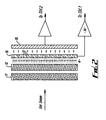
- a mass spectrometer is shown in schematic form in Fig. 2 .
- the ion beam generated by the ion source (not shown) is also incident on a chevron pair 11, 12 as with the embodiment of Fig. 1 .
- the ion beam strikes the micochannel plate 11 and causes the ejection of secondary electrons from the surface of the microchannels.
- the secondary electrons cause the ejection of further secondary electrons as they accelerate through the microchannels in the plates 11,12 which results in an electron beam which emerges from the chevron pair 11,12 being essentially an amplified signal version of the incoming ion beam.
- the secondary electron beam then strikes a first anode 16 for detection.
- the first anode 16 is perforated in order that some of the secondary electrons pass through the first anode 16 without being detected. The remainder of the secondary electrons strike the first anode 16 and are detected.
- the first anode 16 is connected to an amplifier 14 and to a time to digital converter (not shown) the output of which increments a counter (not shown) as previously explained.
- Those secondary electrons which pass through the perforations 17 in the first anode 16 strike a second anode 18 placed substantially immediately behind the first anode 16 and are detected.
- the secondary anode is connected to a second amplifier and a second time to digital converter, the output of which increments a counter in the same manner as mentioned above.
- the ratio of the cross-sectional area of the perforations to the total cross-sectional area of the anode can be chosen to give a particular degree of attenuation to the incoming secondary electron beam.
- the ion beam is directed onto the chevron pair 11,12. This results in the generation of secondary electrons in the manner mentioned above. These secondary electrons emerge from the chevron pair 11,12 and are incident of the first anode 16. It is thought that by arranging for the cross-sectional area of the perforations in the first anode to be of the order of 1 % of the total cross-sectional area of the anode will give the possibility for more accurate quantitative measurements over a large dynamic range, however, it is to be appreciated that the ratio of the cross-sectional area of the perforations to the total area of the anode can be of any desired magnitude in order to give appropriate attenuation characteristics.
- the area of the perforations represents approximately 1 % of the total area of the anode, this means that 1 % of the secondary electron beam which is incident on the first anode 16 will pass through that anode without being detected.
- Fig. 3 shows a variation on the arrangement of Fig. 2 in which an earthed grid 19 is positioned between the first and second anode 16 and 18.
- the earthed grid 19 assists in the minirnisation of capacitative coupling effects between the two anodes 16 and 18.
- Attenuation of the secondary electron signal is carried out by the perforated first anode 16
- attenuation can be carried out in many different ways.
- the attenuation can be carried out by wires or a grid placed in front of the first anode 16 to form the second anode 18.
- the cross-sectional area of the wire or grid compared to the cross-sectional area of the first plate anode is small such that a large proportion of the incident signal from the chevron pair 11,12 passes through the second anode 18 without being detected.
- the attenuation can be varied by changing the cross-sectional area of the wire or grid to achieve a desired dynamic range.
- an earthed grid 19 can be placed between the two anodes to minimise capacitative coupling of these anodes.
- first anode 16 a second anode 18 and, optionally an earthed grid 19, are constructed as sandwich layers of a printed circuit board 21.
- the first anode 16 is formed as a perforated plate attached to a first support layer 22 which is also perforated, the perforations in the first support layer 22 being in register with the perforations in the first anode 16.
- Attached to the opposite side of the first support layer 22 is an earthed grid, perforations in the grid also being in register with the perforations in the first support layer 22 and the first anode 16.
- Attached to the opposite side of the earthed grid 19 is a second support layer 23 which carries a second anode 18 attached thereto. Fingers 24 of the second anode 18 extend through the second support layer 23 and terminate adjacent to the perforations in the earthed grid 19.
- the attenuation is carried out by the first anode 16 and only a proportion of the secondary electrons reach the fingers 24 of the second anode 18 through the aligned apertures.
- the earthed grid 19 minimises capacitative coupling between the two anodes.
- Figs. 2-5 are not embodiments of a mass spectrometer in accordance with the present invention.
- a first embodiment of the present invention is shown in Fig. 6 in which a separate attenuation element 26 of appropriate form is placed in the ion beam before the ion beam is incident on the chevron pair 11, 12.
- the attenuation element in this embodiment comprises a perforated plate, and is arranged so as to interfere only with a part of the incoming ion beam and reduces the proportion of that part of the beam which reaches the chevron pair 11,12.
- the first anode 16 and the second anode 18 are also provided but they are provided in the same plane extending generally parallel to the longitudinal axis of the chevron pair 11,12 as spaced therefrom.
- the attenuation element attenuates only a part of the incoming ion beam which, after passing through the chevron pair 11,12 and generating secondary electrons, is incident on the second anode 18.
- the unattenuated part of the incoming ion beam after passing through the chevron pair 11,12 is incident on the first anode 16. Therefore it will be appreciated that the same effect is achieved with this embodiment as is achieved in the arrangements described above.
- the overall attenuation required may also be achieved by a combination of attenuation of the incident ion beam reaching an area of the microchannel plates detector and attenuation of the secondary electron signal, for example Fig. 7 .
- Attenuation can be achieved by a combination of restricting the proportion of ion beam reaching a part of the chevron pair 11,12 (as in the embodiment of Fig. 6 ) with a restriction on the secondary electron signal emerging from the chevron pair (as in the arrangement of Fig. 4 ).
- An example of an embodiment of this type is shown in Fig. 7 .
- the incident ion beam is attenuated by a perforated member placed before the chevron pair 11,12.
- the secondary electron signal emerging from the chevron pair 11.12 is attenuated by placing a relatively small second anode in front of an relatively large first anode.
- Attenuation of the incoming ion beam or the secondary electrons ejected from the chevron pair 11,12 which allows the TDC elements to more accurately count incoming ions over a large dynamic range.
- the use of attenuation means that it is possible to discriminate between different magnitude above threshold signals giving rise to a more accurate quantitative analysis of the incoming ion beam and also giving rise to an extension to the dynamic range of the mass spectrometer.
Landscapes
- Chemical & Material Sciences (AREA)
- Analytical Chemistry (AREA)
- Electron Tubes For Measurement (AREA)
- Other Investigation Or Analysis Of Materials By Electrical Means (AREA)
Claims (8)
- Massenspektrometer, umfassend:eine Ionenquelle, ein Detektormittel, ein Dämpfungsmittel (26), Mikrokanalplatten (11, 12), einen Zeit-zu-Digital-Wandler (TDC1, TDC2) und einen Analog-zu-Digital-Wandler, wobeidie Ionenquelle so betreibbar ist, dass sie Ionen von einer zu detektierenden Substanz erzeugt;das Detektormittel so betreibbar ist, dass es eine Menge von auf dem Detektormittel auftreffenden Ionen detektiert, wobei das Detektormittel wenigstens zwei Detektorelemente (16, 18) enthält, einschließlich eines ersten Detektorelements (16) und eines zweiten Detektorelements (18), wobei jedes der Detektorelemente (16, 18) so ausgeführt ist, dass es wenigstens einen Teil der Menge der Ionen von der Ionenquelle detektiert;das Dämpfungsmittel (26) so betreibbar ist, dass es eine Dämpfung der Menge von Ionen, die das zweite Detektorelement (18) erreichen, relativ zum ersten Detektorelement (16) bewirkt,
wobei wenigstens eines der Detektorelemente (16, 18) mit dem Zeit-zu-Digital-Wandler (TDC1, TDC2) verbunden ist, um ein Zählen von detektierten Ionen zu erlauben; dadurch gekennzeichnet, dass:das Dämpfungsmittel (26) zwischen der Ionenquelle und den Mikrokanalplatten (11, 12) platziert ist, undwenigstens eines der Detektorelemente (16, 18) parallel sowohl zu dem Zeit-zu-Digital-Wandler (TDC1, TDC2) als auch zu dem Analog-zu-Digital-Wandler zur lonendetektion verbunden ist. - Massenspektrometer nach Anspruch 1, wobei jedes Detektorelement (16, 18) eine separate Plattenanode umfasst.
- Massenspektrometer nach Anspruch 1 oder Anspruch 2, wobei jedes Detektorelement (16, 18) über einen Verstärker (14) mit einem Zeit-zu-Digital-Wandler (TDC1, TDC2) verbunden ist, um das Zählen detektierter Ionen zu erlauben.
- Massenspektrometer nach irgendeinem der Ansprüche 1 bis 3, wobei die Detektorelemente (16, 18) relativ zur Ionenquelle hintereinander angeordnet sind.
- Massenspektrometer nach irgendeinem der Ansprüche 1 bis 3, wobei die Detektorelemente (16, 18) in einer Ebene, die sich im Wesentlichen senkrecht zur Bewegungsrichtung der Ionen erstreckt, übereinander angeordnet sind.
- Massenspektrometer nach Anspruch 4, wobei ein geerdetes Gitter zwischen den Elementen (16, 18) vorgesehen ist, um eine kapazitive Kopplung zwischen den Elementen (16, 18) zu minimieren.
- Massenspektrometer nach irgendeinem der Ansprüche 1 bis 6, wobei das Dämpfungsmittel (26) zwischen der Ionenquelle und den Detektorelementen (16, 18) vorgesehen ist und eine Reduzierung der Anzahl der Ionen bewirkt, die wenigstens eines der Elemente (16, 18) oder wenigstens einen Teil desselben erreichen.
- Massenspektrometer nach Anspruch 7, wobei das Dämpfungsmittel (26) eine perforierte Platte umfasst.
Applications Claiming Priority (3)
| Application Number | Priority Date | Filing Date | Title |
|---|---|---|---|
| GBGB9920711.0A GB9920711D0 (en) | 1999-09-03 | 1999-09-03 | High dynamic range mass spectrometer |
| GB9920711 | 1999-09-03 | ||
| PCT/GB2000/003332 WO2001018846A2 (en) | 1999-09-03 | 2000-08-31 | High dynamic range mass spectrometer |
Publications (2)
| Publication Number | Publication Date |
|---|---|
| EP1224686A2 EP1224686A2 (de) | 2002-07-24 |
| EP1224686B1 true EP1224686B1 (de) | 2008-10-01 |
Family
ID=10860194
Family Applications (1)
| Application Number | Title | Priority Date | Filing Date |
|---|---|---|---|
| EP00960829A Expired - Lifetime EP1224686B1 (de) | 1999-09-03 | 2000-08-31 | Massenspektrometer mit grossem dynamischem bereich |
Country Status (8)
| Country | Link |
|---|---|
| US (2) | US6864479B1 (de) |
| EP (1) | EP1224686B1 (de) |
| JP (1) | JP4869526B2 (de) |
| AT (1) | ATE409952T1 (de) |
| CA (1) | CA2382516C (de) |
| DE (1) | DE60040407D1 (de) |
| GB (1) | GB9920711D0 (de) |
| WO (1) | WO2001018846A2 (de) |
Families Citing this family (65)
| Publication number | Priority date | Publication date | Assignee | Title |
|---|---|---|---|---|
| GB9920711D0 (en) * | 1999-09-03 | 1999-11-03 | Hd Technologies Limited | High dynamic range mass spectrometer |
| CA2448332C (en) * | 2001-05-25 | 2009-04-14 | Analytica Of Branford, Inc. | Multiple detection systems |
| GB2381373B (en) * | 2001-05-29 | 2005-03-23 | Thermo Masslab Ltd | Time of flight mass spectrometer and multiple detector therefor |
| US6747271B2 (en) | 2001-12-19 | 2004-06-08 | Ionwerks | Multi-anode detector with increased dynamic range for time-of-flight mass spectrometers with counting data acquisition |
| DE10206173B4 (de) | 2002-02-14 | 2006-08-31 | Bruker Daltonik Gmbh | Hochauflösende Detektion für Flugzeitmassenspektrometer |
| US7563600B2 (en) | 2002-09-12 | 2009-07-21 | Combimatrix Corporation | Microarray synthesis and assembly of gene-length polynucleotides |
| EP1569741A4 (de) * | 2002-11-27 | 2008-07-23 | Ionwerks Inc | Flugzeitmassenspektrometermit verbessertem datenerfassungssystem |
| GB0409118D0 (en) * | 2004-04-26 | 2004-05-26 | Micromass Ltd | Mass spectrometer |
| US9956639B2 (en) | 2005-02-07 | 2018-05-01 | Lincoln Global, Inc | Modular power source for electric ARC welding and output chopper |
| US8785816B2 (en) | 2004-07-13 | 2014-07-22 | Lincoln Global, Inc. | Three stage power source for electric arc welding |
| US8581147B2 (en) * | 2005-03-24 | 2013-11-12 | Lincoln Global, Inc. | Three stage power source for electric ARC welding |
| US8269141B2 (en) | 2004-07-13 | 2012-09-18 | Lincoln Global, Inc. | Power source for electric arc welding |
| US9855620B2 (en) | 2005-02-07 | 2018-01-02 | Lincoln Global, Inc. | Welding system and method of welding |
| US9647555B2 (en) * | 2005-04-08 | 2017-05-09 | Lincoln Global, Inc. | Chopper output stage for arc welder power source |
| US20070090287A1 (en) * | 2005-10-20 | 2007-04-26 | Foote James D | Intelligent SIM acquisition |
| US7649180B2 (en) * | 2005-12-21 | 2010-01-19 | Searete Llc | Multi-stage waveform detector |
| US7649182B2 (en) * | 2006-10-26 | 2010-01-19 | Searete Llc | Variable multi-stage waveform detector |
| US8207907B2 (en) * | 2006-02-16 | 2012-06-26 | The Invention Science Fund I Llc | Variable metamaterial apparatus |
| US7601967B2 (en) * | 2005-12-21 | 2009-10-13 | Searete Llc | Multi-stage waveform detector |
| US7427762B2 (en) * | 2005-12-21 | 2008-09-23 | Searete Llc | Variable multi-stage waveform detector |
| US7391032B1 (en) * | 2005-12-21 | 2008-06-24 | Searete Llc | Multi-stage waveform detector |
| JP2008059774A (ja) * | 2006-08-29 | 2008-03-13 | Hitachi High-Technologies Corp | 飛行時間型質量分析装置 |
| US20080054175A1 (en) * | 2006-08-30 | 2008-03-06 | Nic Bloomfield | Systems and methods for correcting for unequal ion distribution across a multi-channel tof detector |
| US8053191B2 (en) | 2006-08-31 | 2011-11-08 | Westend Asset Clearinghouse Company, Llc | Iterative nucleic acid assembly using activation of vector-encoded traits |
| GB0709799D0 (en) | 2007-05-22 | 2007-06-27 | Micromass Ltd | Mass spectrometer |
| GB2467548B (en) * | 2009-02-04 | 2013-02-27 | Nu Instr Ltd | Detection arrangements in mass spectrometers |
| US10207240B2 (en) | 2009-11-03 | 2019-02-19 | Gen9, Inc. | Methods and microfluidic devices for the manipulation of droplets in high fidelity polynucleotide assembly |
| WO2011066185A1 (en) | 2009-11-25 | 2011-06-03 | Gen9, Inc. | Microfluidic devices and methods for gene synthesis |
| WO2011085075A2 (en) | 2010-01-07 | 2011-07-14 | Gen9, Inc. | Assembly of high fidelity polynucleotides |
| JP5781545B2 (ja) * | 2010-02-02 | 2015-09-24 | ディーエイチ テクノロジーズ デベロップメント プライベート リミテッド | 飛行時間型質量分析検出システムを操作する方法およびシステム |
| DE102010032823B4 (de) * | 2010-07-30 | 2013-02-07 | Ion-Tof Technologies Gmbh | Verfahren sowie ein Massenspektrometer zum Nachweis von Ionen oder nachionisierten Neutralteilchen aus Proben |
| EP2606504A2 (de) * | 2010-08-19 | 2013-06-26 | DH Technologies Development Pte. Ltd. | Verfahren und system zur erhöhung des dynamischen bereichs von ionendetektoren |
| EP4039363A1 (de) | 2010-11-12 | 2022-08-10 | Gen9, Inc. | Proteinanordnungen und verfahren zu ihrer herstellung und verwendung |
| AU2011338841B2 (en) | 2010-11-12 | 2017-02-16 | Gen9, Inc. | Methods and devices for nucleic acids synthesis |
| GB2486484B (en) | 2010-12-17 | 2013-02-20 | Thermo Fisher Scient Bremen | Ion detection system and method |
| JP5771447B2 (ja) * | 2011-06-02 | 2015-08-26 | 浜松ホトニクス株式会社 | 電子増倍器 |
| IL302248A (en) | 2011-08-26 | 2023-06-01 | Gen9 Inc | Compositions and methods for high fidelity assembly of nucleic acids |
| US9150853B2 (en) | 2012-03-21 | 2015-10-06 | Gen9, Inc. | Methods for screening proteins using DNA encoded chemical libraries as templates for enzyme catalysis |
| WO2013163263A2 (en) | 2012-04-24 | 2013-10-31 | Gen9, Inc. | Methods for sorting nucleic acids and multiplexed preparative in vitro cloning |
| US20150191719A1 (en) | 2012-06-25 | 2015-07-09 | Gen9, Inc. | Methods for Nucleic Acid Assembly and High Throughput Sequencing |
| US10354849B2 (en) | 2013-07-09 | 2019-07-16 | Micromass Uk Limited | Method of recording ADC saturation |
| GB201312266D0 (en) * | 2013-07-09 | 2013-08-21 | Micromass Ltd | Method of recording ADC saturation |
| GB201513167D0 (en) | 2015-07-27 | 2015-09-09 | Thermo Fisher Scient Bremen | Elemental analysis of organic samples |
| GB201613988D0 (en) | 2016-08-16 | 2016-09-28 | Micromass Uk Ltd And Leco Corp | Mass analyser having extended flight path |
| US9899201B1 (en) * | 2016-11-09 | 2018-02-20 | Bruker Daltonics, Inc. | High dynamic range ion detector for mass spectrometers |
| GB2567794B (en) | 2017-05-05 | 2023-03-08 | Micromass Ltd | Multi-reflecting time-of-flight mass spectrometers |
| GB2563571B (en) | 2017-05-26 | 2023-05-24 | Micromass Ltd | Time of flight mass analyser with spatial focussing |
| EP3662501A1 (de) | 2017-08-06 | 2020-06-10 | Micromass UK Limited | Ionenspiegel für multireflektierendes massenspektrometer |
| WO2019030474A1 (en) | 2017-08-06 | 2019-02-14 | Anatoly Verenchikov | IONIC MIRROR WITH PRINTED CIRCUIT WITH COMPENSATION |
| US11817303B2 (en) | 2017-08-06 | 2023-11-14 | Micromass Uk Limited | Accelerator for multi-pass mass spectrometers |
| US11211238B2 (en) | 2017-08-06 | 2021-12-28 | Micromass Uk Limited | Multi-pass mass spectrometer |
| US11205568B2 (en) | 2017-08-06 | 2021-12-21 | Micromass Uk Limited | Ion injection into multi-pass mass spectrometers |
| WO2019030471A1 (en) | 2017-08-06 | 2019-02-14 | Anatoly Verenchikov | ION GUIDE INSIDE PULSED CONVERTERS |
| US11049712B2 (en) | 2017-08-06 | 2021-06-29 | Micromass Uk Limited | Fields for multi-reflecting TOF MS |
| GB201806507D0 (en) | 2018-04-20 | 2018-06-06 | Verenchikov Anatoly | Gridless ion mirrors with smooth fields |
| GB201807605D0 (en) | 2018-05-10 | 2018-06-27 | Micromass Ltd | Multi-reflecting time of flight mass analyser |
| GB201807626D0 (en) | 2018-05-10 | 2018-06-27 | Micromass Ltd | Multi-reflecting time of flight mass analyser |
| GB201808530D0 (en) | 2018-05-24 | 2018-07-11 | Verenchikov Anatoly | TOF MS detection system with improved dynamic range |
| GB201810573D0 (en) | 2018-06-28 | 2018-08-15 | Verenchikov Anatoly | Multi-pass mass spectrometer with improved duty cycle |
| GB201901411D0 (en) | 2019-02-01 | 2019-03-20 | Micromass Ltd | Electrode assembly for mass spectrometer |
| GB201903779D0 (en) | 2019-03-20 | 2019-05-01 | Micromass Ltd | Multiplexed time of flight mass spectrometer |
| JP7333292B2 (ja) | 2020-06-11 | 2023-08-24 | 浜松ホトニクス株式会社 | イオン検出器 |
| JP7330138B2 (ja) | 2020-06-11 | 2023-08-21 | 浜松ホトニクス株式会社 | イオン検出器 |
| CN115565848A (zh) * | 2022-10-13 | 2023-01-03 | 昆山禾信质谱技术有限公司 | 质谱仪光学系统检测设备及其方法、装置和存储介质 |
| CN117434820B (zh) * | 2023-12-19 | 2024-08-27 | 杭州谱育科技发展有限公司 | 一种时间数字转换器及飞行时间质谱仪 |
Family Cites Families (29)
| Publication number | Priority date | Publication date | Assignee | Title |
|---|---|---|---|---|
| GB907511A (en) | 1959-07-31 | 1962-10-03 | Atomic Energy Authority Uk | Method of detecting ions |
| GB1147667A (en) | 1966-11-03 | 1969-04-02 | Univ Schiller Jena | Improvements in or relating to mass spectrometers |
| JPS50110693A (de) * | 1974-02-12 | 1975-08-30 | ||
| JPS60121657A (ja) | 1983-11-11 | 1985-06-29 | Anelva Corp | 測定装置 |
| JPS62160456A (ja) * | 1986-01-09 | 1987-07-16 | Canon Inc | 電子写真感光体 |
| JPH0346456Y2 (de) * | 1986-03-31 | 1991-10-01 | ||
| JPS63193452A (ja) * | 1987-02-05 | 1988-08-10 | Nec Corp | 二次イオン質量分析計 |
| JP2585616B2 (ja) | 1987-08-12 | 1997-02-26 | 株式会社日立製作所 | 二次イオン質量分析計方法 |
| US5026988A (en) | 1989-09-19 | 1991-06-25 | Vanderbilt University | Method and apparatus for time of flight medium energy particle scattering |
| DE4019005C2 (de) | 1990-06-13 | 2000-03-09 | Finnigan Mat Gmbh | Vorrichtungen zur Analyse von Ionen hoher Masse |
| JPH0466862A (ja) * | 1990-07-06 | 1992-03-03 | Hitachi Ltd | 高感度元素分析法及び装置 |
| US5077470A (en) * | 1991-01-11 | 1991-12-31 | Jeol Ltd. | Mass spectrometer |
| JPH06150876A (ja) | 1992-11-09 | 1994-05-31 | Hamamatsu Photonics Kk | 光電子増倍管及び電子増倍管 |
| DE19502439B4 (de) | 1994-02-11 | 2007-08-16 | Oc Oerlikon Balzers Ag | Verfahren und Messanordnung zum Messen der pro Zeiteinheit einen Vakuumvolumenbereich in gegebener Richtung durchströmenden elektrischen Ladungsmenge und deren Verwendung für Massenspektrometer |
| US6011259A (en) | 1995-08-10 | 2000-01-04 | Analytica Of Branford, Inc. | Multipole ion guide ion trap mass spectrometry with MS/MSN analysis |
| US5644128A (en) | 1994-08-25 | 1997-07-01 | Ionwerks | Fast timing position sensitive detector |
| US5463219A (en) | 1994-12-07 | 1995-10-31 | Mds Health Group Limited | Mass spectrometer system and method using simultaneous mode detector and signal region flags |
| DE19635645C2 (de) | 1996-09-03 | 2000-12-28 | Bruker Daltonik Gmbh | Verfahren für die hochauflösende Spektrenaufnahme von Analytionen in einem linearen Flugzeitmassenspektrometer |
| WO1998021742A1 (en) * | 1996-11-15 | 1998-05-22 | Sensar Corporation | Multi-anode time to digital converter |
| US5777326A (en) * | 1996-11-15 | 1998-07-07 | Sensor Corporation | Multi-anode time to digital converter |
| AUPO557797A0 (en) | 1997-03-12 | 1997-04-10 | Gbc Scientific Equipment Pty Ltd | A time of flight analysis device |
| JP3254164B2 (ja) * | 1997-04-30 | 2002-02-04 | 科学技術振興事業団 | イメージングマイクロストリップガスチャンバー |
| JPH11213941A (ja) * | 1998-01-23 | 1999-08-06 | Jeol Ltd | 質量分析システム |
| US6229142B1 (en) | 1998-01-23 | 2001-05-08 | Micromass Limited | Time of flight mass spectrometer and detector therefor |
| US6348688B1 (en) | 1998-02-06 | 2002-02-19 | Perseptive Biosystems | Tandem time-of-flight mass spectrometer with delayed extraction and method for use |
| US6646252B1 (en) | 1998-06-22 | 2003-11-11 | Marc Gonin | Multi-anode detector with increased dynamic range for time-of-flight mass spectrometers with counting data acquisition |
| WO1999067801A2 (en) | 1998-06-22 | 1999-12-29 | Ionwerks | A multi-anode detector with increased dynamic range for time-of-flight mass spectrometers with counting data acquisition |
| GB9920711D0 (en) * | 1999-09-03 | 1999-11-03 | Hd Technologies Limited | High dynamic range mass spectrometer |
| DE10010902A1 (de) | 2000-03-07 | 2001-09-20 | Bruker Daltonik Gmbh | Tandem-Massenspektrometer aus zwei Quadrupolfiltern |
-
1999
- 1999-09-03 GB GBGB9920711.0A patent/GB9920711D0/en not_active Ceased
-
2000
- 2000-08-31 WO PCT/GB2000/003332 patent/WO2001018846A2/en not_active Ceased
- 2000-08-31 AT AT00960829T patent/ATE409952T1/de not_active IP Right Cessation
- 2000-08-31 JP JP2001522571A patent/JP4869526B2/ja not_active Expired - Fee Related
- 2000-08-31 EP EP00960829A patent/EP1224686B1/de not_active Expired - Lifetime
- 2000-08-31 CA CA002382516A patent/CA2382516C/en not_active Expired - Fee Related
- 2000-08-31 US US10/070,118 patent/US6864479B1/en not_active Expired - Lifetime
- 2000-08-31 DE DE60040407T patent/DE60040407D1/de not_active Expired - Lifetime
-
2005
- 2005-02-11 US US11/056,530 patent/US6969847B2/en not_active Expired - Lifetime
Also Published As
| Publication number | Publication date |
|---|---|
| DE60040407D1 (de) | 2008-11-13 |
| CA2382516C (en) | 2007-02-13 |
| GB9920711D0 (en) | 1999-11-03 |
| WO2001018846A3 (en) | 2001-11-15 |
| CA2382516A1 (en) | 2001-03-15 |
| ATE409952T1 (de) | 2008-10-15 |
| US20050145788A1 (en) | 2005-07-07 |
| JP2003509812A (ja) | 2003-03-11 |
| WO2001018846A2 (en) | 2001-03-15 |
| EP1224686A2 (de) | 2002-07-24 |
| US6864479B1 (en) | 2005-03-08 |
| JP4869526B2 (ja) | 2012-02-08 |
| US6969847B2 (en) | 2005-11-29 |
Similar Documents
| Publication | Publication Date | Title |
|---|---|---|
| EP1224686B1 (de) | Massenspektrometer mit grossem dynamischem bereich | |
| US5644128A (en) | Fast timing position sensitive detector | |
| US6747271B2 (en) | Multi-anode detector with increased dynamic range for time-of-flight mass spectrometers with counting data acquisition | |
| US8575544B1 (en) | Methods and devices for improving atom probe detector performance | |
| US5591969A (en) | Inductive detector for time-of-flight mass spectrometers | |
| JP5686309B2 (ja) | 質量分析装置における検出構成 | |
| US4584474A (en) | Electron energy analyzer with multi-channel detector | |
| EP1747572B1 (de) | Massenspektrometer | |
| AU2001262880B2 (en) | Apparatus and method for radiation detection | |
| WO2009027252A2 (de) | Vorrichtung zur messung eines teilchenstroms | |
| JP6897870B2 (ja) | 飛行時間型質量分析装置 | |
| Knibbeler et al. | Novel two‐dimensional position‐sensitive detection system | |
| US6031227A (en) | Time-of-flight mass spectrometer with position-sensitive detection | |
| US3691382A (en) | Low energy particle counter with one-dimensional position sensing | |
| Wiggins et al. | Achieving high spatial resolution using a microchannel plate detector with an economic and scalable approach | |
| US7791018B2 (en) | Electronic read-out circuits for pixilated/resistive charge detectors | |
| Rehm et al. | Measurements of heavy-ion induced fusion cross sections with the gas-filled-magnet technique | |
| US11823881B2 (en) | Elementary particle detector | |
| Chattopadhay et al. | Performance of a real-size, low resistivity resistive plate chamber at GIF++ Using self-trigger electronics for the Muon Chamber of the CBM Experiment | |
| US6815689B1 (en) | Mass spectrometry with enhanced particle flux range | |
| JPH0336029Y2 (de) | ||
| US3413479A (en) | Radiation detector and amplifier having an input axial slot | |
| Bencivenni et al. | A fast multi-GEM-based detector for high-rate charged-particle triggering | |
| JPH046741A (ja) | 質量分析計のイオン検出器 | |
| GB2266407A (en) | Charged particle analyser |
Legal Events
| Date | Code | Title | Description |
|---|---|---|---|
| PUAI | Public reference made under article 153(3) epc to a published international application that has entered the european phase |
Free format text: ORIGINAL CODE: 0009012 |
|
| 17P | Request for examination filed |
Effective date: 20020308 |
|
| AK | Designated contracting states |
Kind code of ref document: A2 Designated state(s): AT BE CH CY DE DK ES FI FR GB GR IE IT LI LU MC NL PT SE |
|
| RAP1 | Party data changed (applicant data changed or rights of an application transferred) |
Owner name: THERMO FINNIGAN LLC |
|
| 17Q | First examination report despatched |
Effective date: 20061221 |
|
| 17Q | First examination report despatched |
Effective date: 20061221 |
|
| GRAP | Despatch of communication of intention to grant a patent |
Free format text: ORIGINAL CODE: EPIDOSNIGR1 |
|
| GRAS | Grant fee paid |
Free format text: ORIGINAL CODE: EPIDOSNIGR3 |
|
| GRAA | (expected) grant |
Free format text: ORIGINAL CODE: 0009210 |
|
| AK | Designated contracting states |
Kind code of ref document: B1 Designated state(s): AT BE CH CY DE DK ES FI FR GB GR IE IT LI LU MC NL PT SE |
|
| REG | Reference to a national code |
Ref country code: GB Ref legal event code: FG4D |
|
| REG | Reference to a national code |
Ref country code: CH Ref legal event code: EP |
|
| REG | Reference to a national code |
Ref country code: IE Ref legal event code: FG4D |
|
| REF | Corresponds to: |
Ref document number: 60040407 Country of ref document: DE Date of ref document: 20081113 Kind code of ref document: P |
|
| NLV1 | Nl: lapsed or annulled due to failure to fulfill the requirements of art. 29p and 29m of the patents act | ||
| PG25 | Lapsed in a contracting state [announced via postgrant information from national office to epo] |
Ref country code: ES Free format text: LAPSE BECAUSE OF FAILURE TO SUBMIT A TRANSLATION OF THE DESCRIPTION OR TO PAY THE FEE WITHIN THE PRESCRIBED TIME-LIMIT Effective date: 20090112 Ref country code: AT Free format text: LAPSE BECAUSE OF FAILURE TO SUBMIT A TRANSLATION OF THE DESCRIPTION OR TO PAY THE FEE WITHIN THE PRESCRIBED TIME-LIMIT Effective date: 20081001 |
|
| PG25 | Lapsed in a contracting state [announced via postgrant information from national office to epo] |
Ref country code: NL Free format text: LAPSE BECAUSE OF FAILURE TO SUBMIT A TRANSLATION OF THE DESCRIPTION OR TO PAY THE FEE WITHIN THE PRESCRIBED TIME-LIMIT Effective date: 20081001 Ref country code: FI Free format text: LAPSE BECAUSE OF FAILURE TO SUBMIT A TRANSLATION OF THE DESCRIPTION OR TO PAY THE FEE WITHIN THE PRESCRIBED TIME-LIMIT Effective date: 20081001 Ref country code: PT Free format text: LAPSE BECAUSE OF FAILURE TO SUBMIT A TRANSLATION OF THE DESCRIPTION OR TO PAY THE FEE WITHIN THE PRESCRIBED TIME-LIMIT Effective date: 20090302 |
|
| PG25 | Lapsed in a contracting state [announced via postgrant information from national office to epo] |
Ref country code: BE Free format text: LAPSE BECAUSE OF FAILURE TO SUBMIT A TRANSLATION OF THE DESCRIPTION OR TO PAY THE FEE WITHIN THE PRESCRIBED TIME-LIMIT Effective date: 20081001 Ref country code: DK Free format text: LAPSE BECAUSE OF FAILURE TO SUBMIT A TRANSLATION OF THE DESCRIPTION OR TO PAY THE FEE WITHIN THE PRESCRIBED TIME-LIMIT Effective date: 20081001 |
|
| PLBE | No opposition filed within time limit |
Free format text: ORIGINAL CODE: 0009261 |
|
| STAA | Information on the status of an ep patent application or granted ep patent |
Free format text: STATUS: NO OPPOSITION FILED WITHIN TIME LIMIT |
|
| PG25 | Lapsed in a contracting state [announced via postgrant information from national office to epo] |
Ref country code: IT Free format text: LAPSE BECAUSE OF FAILURE TO SUBMIT A TRANSLATION OF THE DESCRIPTION OR TO PAY THE FEE WITHIN THE PRESCRIBED TIME-LIMIT Effective date: 20081001 Ref country code: SE Free format text: LAPSE BECAUSE OF FAILURE TO SUBMIT A TRANSLATION OF THE DESCRIPTION OR TO PAY THE FEE WITHIN THE PRESCRIBED TIME-LIMIT Effective date: 20090101 |
|
| 26N | No opposition filed |
Effective date: 20090702 |
|
| PG25 | Lapsed in a contracting state [announced via postgrant information from national office to epo] |
Ref country code: MC Free format text: LAPSE BECAUSE OF NON-PAYMENT OF DUE FEES Effective date: 20090831 |
|
| REG | Reference to a national code |
Ref country code: CH Ref legal event code: PL |
|
| PG25 | Lapsed in a contracting state [announced via postgrant information from national office to epo] |
Ref country code: LI Free format text: LAPSE BECAUSE OF NON-PAYMENT OF DUE FEES Effective date: 20090831 Ref country code: CH Free format text: LAPSE BECAUSE OF NON-PAYMENT OF DUE FEES Effective date: 20090831 |
|
| REG | Reference to a national code |
Ref country code: FR Ref legal event code: ST Effective date: 20100430 |
|
| REG | Reference to a national code |
Ref country code: IE Ref legal event code: MM4A |
|
| PG25 | Lapsed in a contracting state [announced via postgrant information from national office to epo] |
Ref country code: IE Free format text: LAPSE BECAUSE OF NON-PAYMENT OF DUE FEES Effective date: 20090831 Ref country code: FR Free format text: LAPSE BECAUSE OF NON-PAYMENT OF DUE FEES Effective date: 20090831 |
|
| PG25 | Lapsed in a contracting state [announced via postgrant information from national office to epo] |
Ref country code: GR Free format text: LAPSE BECAUSE OF FAILURE TO SUBMIT A TRANSLATION OF THE DESCRIPTION OR TO PAY THE FEE WITHIN THE PRESCRIBED TIME-LIMIT Effective date: 20090102 |
|
| PG25 | Lapsed in a contracting state [announced via postgrant information from national office to epo] |
Ref country code: LU Free format text: LAPSE BECAUSE OF NON-PAYMENT OF DUE FEES Effective date: 20090831 |
|
| PG25 | Lapsed in a contracting state [announced via postgrant information from national office to epo] |
Ref country code: CY Free format text: LAPSE BECAUSE OF FAILURE TO SUBMIT A TRANSLATION OF THE DESCRIPTION OR TO PAY THE FEE WITHIN THE PRESCRIBED TIME-LIMIT Effective date: 20081001 |
|
| PGFP | Annual fee paid to national office [announced via postgrant information from national office to epo] |
Ref country code: DE Payment date: 20180821 Year of fee payment: 19 |
|
| PGFP | Annual fee paid to national office [announced via postgrant information from national office to epo] |
Ref country code: GB Payment date: 20180829 Year of fee payment: 19 |
|
| REG | Reference to a national code |
Ref country code: DE Ref legal event code: R119 Ref document number: 60040407 Country of ref document: DE |
|
| GBPC | Gb: european patent ceased through non-payment of renewal fee |
Effective date: 20190831 |
|
| PG25 | Lapsed in a contracting state [announced via postgrant information from national office to epo] |
Ref country code: DE Free format text: LAPSE BECAUSE OF NON-PAYMENT OF DUE FEES Effective date: 20200303 |
|
| PG25 | Lapsed in a contracting state [announced via postgrant information from national office to epo] |
Ref country code: GB Free format text: LAPSE BECAUSE OF NON-PAYMENT OF DUE FEES Effective date: 20190831 |