EP1224384B1 - Wabenkörper mit mehrlagigem mantel - Google Patents
Wabenkörper mit mehrlagigem mantel Download PDFInfo
- Publication number
- EP1224384B1 EP1224384B1 EP00969537A EP00969537A EP1224384B1 EP 1224384 B1 EP1224384 B1 EP 1224384B1 EP 00969537 A EP00969537 A EP 00969537A EP 00969537 A EP00969537 A EP 00969537A EP 1224384 B1 EP1224384 B1 EP 1224384B1
- Authority
- EP
- European Patent Office
- Prior art keywords
- carrier matrix
- honeycomb body
- layers
- matrix shell
- layer
- Prior art date
- Legal status (The legal status is an assumption and is not a legal conclusion. Google has not performed a legal analysis and makes no representation as to the accuracy of the status listed.)
- Expired - Lifetime
Links
Images

Classifications
-
- F—MECHANICAL ENGINEERING; LIGHTING; HEATING; WEAPONS; BLASTING
- F01—MACHINES OR ENGINES IN GENERAL; ENGINE PLANTS IN GENERAL; STEAM ENGINES
- F01N—GAS-FLOW SILENCERS OR EXHAUST APPARATUS FOR MACHINES OR ENGINES IN GENERAL; GAS-FLOW SILENCERS OR EXHAUST APPARATUS FOR INTERNAL-COMBUSTION ENGINES
- F01N3/00—Exhaust or silencing apparatus having means for purifying, rendering innocuous, or otherwise treating exhaust
- F01N3/08—Exhaust or silencing apparatus having means for purifying, rendering innocuous, or otherwise treating exhaust for rendering innocuous
- F01N3/10—Exhaust or silencing apparatus having means for purifying, rendering innocuous, or otherwise treating exhaust for rendering innocuous by thermal or catalytic conversion of noxious components of exhaust
- F01N3/24—Exhaust or silencing apparatus having means for purifying, rendering innocuous, or otherwise treating exhaust for rendering innocuous by thermal or catalytic conversion of noxious components of exhaust characterised by constructional aspects of converting apparatus
- F01N3/28—Construction of catalytic reactors
- F01N3/2839—Arrangements for mounting catalyst support in housing, e.g. with means for compensating thermal expansion or vibration
- F01N3/2853—Arrangements for mounting catalyst support in housing, e.g. with means for compensating thermal expansion or vibration using mats or gaskets between catalyst body and housing
- F01N3/2857—Arrangements for mounting catalyst support in housing, e.g. with means for compensating thermal expansion or vibration using mats or gaskets between catalyst body and housing the mats or gaskets being at least partially made of intumescent material, e.g. unexpanded vermiculite
-
- F—MECHANICAL ENGINEERING; LIGHTING; HEATING; WEAPONS; BLASTING
- F01—MACHINES OR ENGINES IN GENERAL; ENGINE PLANTS IN GENERAL; STEAM ENGINES
- F01N—GAS-FLOW SILENCERS OR EXHAUST APPARATUS FOR MACHINES OR ENGINES IN GENERAL; GAS-FLOW SILENCERS OR EXHAUST APPARATUS FOR INTERNAL-COMBUSTION ENGINES
- F01N3/00—Exhaust or silencing apparatus having means for purifying, rendering innocuous, or otherwise treating exhaust
- F01N3/08—Exhaust or silencing apparatus having means for purifying, rendering innocuous, or otherwise treating exhaust for rendering innocuous
- F01N3/10—Exhaust or silencing apparatus having means for purifying, rendering innocuous, or otherwise treating exhaust for rendering innocuous by thermal or catalytic conversion of noxious components of exhaust
- F01N3/24—Exhaust or silencing apparatus having means for purifying, rendering innocuous, or otherwise treating exhaust for rendering innocuous by thermal or catalytic conversion of noxious components of exhaust characterised by constructional aspects of converting apparatus
- F01N3/28—Construction of catalytic reactors
- F01N3/2839—Arrangements for mounting catalyst support in housing, e.g. with means for compensating thermal expansion or vibration
- F01N3/2853—Arrangements for mounting catalyst support in housing, e.g. with means for compensating thermal expansion or vibration using mats or gaskets between catalyst body and housing
- F01N3/2864—Arrangements for mounting catalyst support in housing, e.g. with means for compensating thermal expansion or vibration using mats or gaskets between catalyst body and housing the mats or gaskets comprising two or more insulation layers
-
- F—MECHANICAL ENGINEERING; LIGHTING; HEATING; WEAPONS; BLASTING
- F01—MACHINES OR ENGINES IN GENERAL; ENGINE PLANTS IN GENERAL; STEAM ENGINES
- F01N—GAS-FLOW SILENCERS OR EXHAUST APPARATUS FOR MACHINES OR ENGINES IN GENERAL; GAS-FLOW SILENCERS OR EXHAUST APPARATUS FOR INTERNAL-COMBUSTION ENGINES
- F01N2510/00—Surface coverings
- F01N2510/08—Surface coverings for corrosion prevention
-
- F—MECHANICAL ENGINEERING; LIGHTING; HEATING; WEAPONS; BLASTING
- F01—MACHINES OR ENGINES IN GENERAL; ENGINE PLANTS IN GENERAL; STEAM ENGINES
- F01N—GAS-FLOW SILENCERS OR EXHAUST APPARATUS FOR MACHINES OR ENGINES IN GENERAL; GAS-FLOW SILENCERS OR EXHAUST APPARATUS FOR INTERNAL-COMBUSTION ENGINES
- F01N3/00—Exhaust or silencing apparatus having means for purifying, rendering innocuous, or otherwise treating exhaust
- F01N3/02—Exhaust or silencing apparatus having means for purifying, rendering innocuous, or otherwise treating exhaust for cooling, or for removing solid constituents of, exhaust
Definitions
- the invention relates to a honeycomb body, in particular a catalyst carrier body, layered from at least partially structured sheet metal foils and / or wrapped or folded carrier matrix having a plurality of for a fluid flow through substantially parallel to a central longitudinal axis Channels, wherein the honeycomb body has a multilayer jacket.
- Laser beam are set very accurately, otherwise the outer metal foils of the Carrier matrix can be cut during welding or not properly Tie, so that the welded joint between the housing and carrier matrix Duration becomes unstable.
- a honeycomb body consisting of several stacked and entangled layers of corrugated and / or smooth sheets known to be smooth, have overlapping end portions.
- the overlapping ones End sections form an outer layer on the circumference of the carrier matrix, which thus is chosen to be greater than the wall thickness of the surrounding jacket, and therefore easily connected to the jacket, in particular welded, can be.
- Carrier matrix shell of a honeycomb body is known for example from DE 28 56 030 A1, accordingly a carrier matrix with a slotted, open Hollow cylinder shell is surrounded, which is cut from a level Sheet metal piece is produced by rolling. In this slotted open Hollow cylinder jacket is then introduced the carrier matrix under play and then placed between two tools and pressed together, so that in the area of the slot an overlap or depending on the design and Forming the shell results in a butt joint, which is welded.
- honeycomb body assembly is further known, in the carrier matrix is surrounded by a mantle, which in turn is in a separate, concentrically arranged jacket tube substantially of this spaced, i. For example, air gap isolated, is arranged.
- WO 97/11934 known multi-layered carrier matrix shells made of clad steel sheet, which on one side of a middle layer forming Base material is provided from a first stainless steel and on the other Side with a support from a second, from the first stainless steel different stainless steel.
- the layer thicknesses of the conditions in the Usually only about 10% of the total sheet thickness. Even if plated steel sheets in particular to hot gas and wet corrosion conditions are adaptable, they have no good vibration and / or sound-absorbing Properties on, and the layers can not be different axially expand.
- JP 01-0240714 is an off metallic layers constructed honeycomb structure and a double-layered jacket tube 3 has.
- This jacket tube 3 is constructed of two layers 31, 32.
- honeycomb body with a improved, especially good vibration and sound-absorbing Characteristics to indicate carrier matrix coat. Furthermore should the components of the honeycomb body to different amounts against each other, in particular longitudinally, can stretch without a simple and permanent attachment of the carrier matrix to the jacket suffers therefrom. Further the honeycomb body should have a carrier matrix coat, which is a simplified Connection of the carrier matrix on the jacket allowed.
- the invention is based on the idea that produced from a layer Carrier matrix shells of a honeycomb body, in particular catalyst carrier body, for a layered from at least partially structured metal foils and / or wrapped or folded carrier matrix having a plurality of for a fluid flow through substantially parallel to a central longitudinal axis Channels are relatively stiff and swing largely unattenuated, which is what happens when Stop recognizes that they sound like a bell. From at least two, preferably three or more, single, smooth, mutually concentric arranged layers, preferably with substantially the same thickness, of which at least two layers are directly adjacent to each other Carrier matrix shells attenuate vibrations and sound much more. Such Coats, for example, can be easily stacked or rolled produce several layers of steel.
- the layers of the carrier matrix shell are preferably such connected with each other that they are different amounts against each other, in particular longitudinally, can stretch. This will be in advantageously avoided thermally induced voltages and a high Product life ensured.
- the metal foils are preferred over their ends exclusively on the innermost layer of the carrier matrix shell in at least one, preferably lying adjacent to the fluid inlet-side end side of the honeycomb body, Connecting portion, in particular joining technology, connected.
- the ends of the metal foils in addition in one adjacent the fluid exit side end face of the honeycomb body lying Connect connecting portion with the innermost layer.
- the honeycomb body has a total of only a small axial length of For example, less than 60 mm, preferably only about 30 mm, the Ends of the metal foils also over their entire axial length with the innermost Layer of the carrier matrix shell can be connected, thereby advantageously their production is simplified.
- the layers of the carrier matrix shell are at least preferred in subareas mainly connected by joining technology, in particular welded, soldered or glued.
- Symmetrical and asymmetric connecting sections or possibly only partial sections thereof can also alternate between several adjacent layers.
- Connecting portions of the same asymmetric connection are arranged, which offset with respect to the longitudinal axis of each other substantially by 180 ° are opposite.
- the carrier matrix sheath of such a honeycomb body advantageously has a sufficiently high strength to thermal loads, in particular due to temperature differences, to be able to record.
- the layers with each other form-fitting preferably by means of at least one bead each, and the so connected layers with the innermost Location are connected by joining technology.
- all layers of the carrier matrix shell can form fit, preferably be connected to each other by means of at least one bead.
- layers with a smaller thickness than 1.5 times the Thickness of the metal foils in particular a smaller thickness than 1.25 times the Thickness of the sheet metal foils, preferably about the same thickness as the Sheet metal foils, so that the layers of the carrier matrix shell advantageously in about the same temperature-related elongation characteristic as the sheet metal foils the carrier matrix.
- a carrier matrix shell of a honeycomb body with the same long trained layers proposed, wherein at least the outermost layer each one end has a connection bead, whereby the, preferably joining technology, connection of a cone is facilitated in an advantageous manner.
- a cone which has a wall thickness such that the Layers constructed carrier matrix sheath is covered at the end.
- the innermost layer of the carrier matrix shell consists of a hot gas corrosion resistant stainless steel or at least according to the inside coated or plated and / or the expressed position of the carrier matrix shell of a wet corrosion resistant Stainless steel is made or at least correspondingly coated on the outside or is plated. Also, it can be considered that the outermost layer not only Wet corrosion is exposed, but also mechanical stress through Impact with stones or sand or the like.
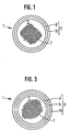
- FIG. 1 shows a highly schematic of a honeycomb body 1 according to the invention, in particular catalyst carrier body, comprising a carrier matrix sheath 2 for one of at least partially structured sheet metal foils 4, 5 layered and / or wound carrier matrix 3 having a plurality of for a fluid flow-through channels 7.
- the carrier matrix jacket 2 of two separate, smooth, concentric with each other arranged layers 8, 10 constructed of substantially the same thickness, which lie directly next to each other.
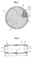
- the carrier matrix shell 2 can also be made of three layers 8, 9 10, such as that in FIG. 3 is shown schematically, or be constructed of more than three layers.
- the Layers 8, 9, 10 of the carrier matrix shell 2 are interconnected so that they stretch by different amounts against each other, in particular axially can.
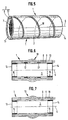
- Fig. 4 shows that in particular to avoid telescoping the carrier matrix 3, the ends 11, 12 of the metal foils 4, 5 additionally in one adjacent to the fluid outlet side end face 14 of the honeycomb body 1 lying Connecting portion 16 are connected to the innermost layer 8.
- the layers 8, 9, 10 of the carrier matrix shell 2 predominantly technical joining are connected to each other, in particular welded, soldered or glued.
- Fig. 4 is also shown that the innermost layer 8 of the carrier matrix shell 2 with the next outer, in the embodiment already the outermost layer 10 of the Carrier matrix shell 2, in a respect to the longitudinal axis 6 of the honeycomb body first arranged symmetrically, preferably approximately in the central region of the Honeycomb body 1 lying, connecting portion 17 are connected.
- connection technology is also suitable for three-ply or multi-ply Carrier matrix shells 2 applicable.
- FIG. 5 An alternative connection of the layers 8, 10, Fig. 5 in a schematic perspective view.
- Contrary to the drawing Representation can such a connection only partially, in particular over a partial angle range, take place.
- Fig. 4 shows that between the layers 8, 10 of the Carrier matrix shell 2 arranged connecting portions 17, 18 of the Connecting portions 15, 16 of the carrier matrix 3 to the innermost layer. 8 spatially as far apart as possible.
- This allows in an advantageous manner Way the components of the honeycomb body 1, to different amounts against each other, in particular longitudinal axial to be able to stretch without a Permanent attachment of the carrier matrix on the jacket suffers.
- symmetrical and asymmetric connection sections can also be layer to layer to be different.
- a carrier matrix shell whose innermost layer with the next outer layer symmetrical and all other layer connections, possibly also only partially, asymmetrically connected (not shown) equally a good vibration and sound damping characteristics such as thermally induced extensibility.
- FIG. 6 Another connection alternative is shown in FIG. 6.
- the layers 9, 10 of the carrier matrix shell 2 together positive fit, preferably by means of at least one interlocking bead 19, for example, as shown by means of an outer bead 19, and the like connected layers 9, 10 with the innermost layer 8 joining technology in adjacent the bead 19 arranged symmetrical connecting portions 17 connected.
- a preferred manufacturing order first sees a careful connection of carrier matrix 3 and innermost layer 8 before, which then in the outermost, preferably prefabricated as a uniform intermediate, layers 9 and 10 is positioned and joined by joining technology.
- all layers 8, 9, 10 of the Carrier matrix shell 2 form-fitting, preferably by means of at least one interlocking bead 19, be connected to each other, wherein the Carrier matrix 3 in turn preferably over adjacent both end faces 13, 14th arranged connecting portions 15, 16 at the innermost layer of the multilayer Carrier matrix shell 2 is connected by joining technology.
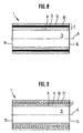
- Fig. 8 shows a honeycomb body 1, in which in particular between the two outermost layers 9,10 of the carrier matrix shell 2 a thin, about 0.5 to 0.8 mm thick, intermediate layer 20, preferably of ceramic material, in particular a swelling mat is arranged, which in an advantageous manner in particular Resonance vibrations absorbs and advantageously in particular at positive connections ensures a certain interference fit.
- Fig. 9 shows a honeycomb body 1, in particular between the two outermost layers 9, 10 of the carrier matrix shell 2 in AxiallCodes reinforce arranged loop-shaped compensator 21, which also in particular receives resonance vibrations. Especially with multi-layered built-up Susunitor and source elements can also cumulative use.
- the layers 8, 9, 10 of the carrier matrix shell 2 are preferred according to the invention a smaller thickness than 1.5 times the thickness of the sheet metal foils 4,5, in particular a thickness smaller than 1.25 times the thickness of the sheet metal foils 4, 5, preferably a same thickness as the sheet metal foils 4, 5, on.
- the layers 8, 9, 10 of the carrier matrix shell 2 are therefore preferred less than or equal to 0.5 mm, in particular less than or equal to 0.4 mm, preferably smaller / equal to 0.3 mm thick.
- the highly schematically shown in Figs. 1 to 11 Layer thicknesses therefore do not correspond to the circumstances but serve the better illustration.
- the carrier matrix jacket 2 according to the embodiment of FIG. 10 has four separate, smooth, mutually concentrically arranged layers of substantially of equal thickness, which lie directly adjacent to each other, the outermost Layer 10 for facilitated connection to a cone 23 axially slightly longer as the inner layer (s) 8, 9 of the carrier matrix shell 2 is formed.
- all the layers of the Queenermatrix mantels 2 also be the same length, at least the outermost layer 10 each end a connection bead 22 to facilitate Connection to a cone 23 has.
- the beads 22 could be so synonymous form (not shown), that at the same time the carrier matrix 3 alternatively or is cumulatively held positively to a joining technology connection.
- the cone 23 preferably has a wall thickness such that the Layers 8, 9, 10 constructed carrier matrix coat 2 is covered frontally.
- the innermost layer 8 of the carrier matrix shell 2 preferably from a produced hot gas corrosion resistant stainless steel or at least accordingly coated or plated on the inside and / or the outer layer 10 of the Supporting matrix shell 2 made of a wet corrosion resistant stainless steel or at least correspondingly coated or plated on the outside, so can be increase the product life of a honeycomb body 1 additionally.
- the honeycomb body 1 according to the invention is characterized due to the advantageous multilayer construction of its carrier matrix shell second in particular by its vibration and sound absorbing properties.
Landscapes
- Chemical & Material Sciences (AREA)
- Chemical Kinetics & Catalysis (AREA)
- Engineering & Computer Science (AREA)
- Health & Medical Sciences (AREA)
- Toxicology (AREA)
- Combustion & Propulsion (AREA)
- Mechanical Engineering (AREA)
- General Engineering & Computer Science (AREA)
- Exhaust Gas After Treatment (AREA)
- Catalysts (AREA)
Applications Claiming Priority (3)
| Application Number | Priority Date | Filing Date | Title |
|---|---|---|---|
| DE19951941 | 1999-10-28 | ||
| DE19951941A DE19951941C1 (de) | 1999-10-28 | 1999-10-28 | Wabenkörper mit mehrlagigem Mantel |
| PCT/EP2000/010431 WO2001031175A1 (de) | 1999-10-28 | 2000-10-23 | Wabenkörper mit mehrlagigem mantel |
Publications (2)
| Publication Number | Publication Date |
|---|---|
| EP1224384A1 EP1224384A1 (de) | 2002-07-24 |
| EP1224384B1 true EP1224384B1 (de) | 2005-03-02 |
Family
ID=7927172
Family Applications (1)
| Application Number | Title | Priority Date | Filing Date |
|---|---|---|---|
| EP00969537A Expired - Lifetime EP1224384B1 (de) | 1999-10-28 | 2000-10-23 | Wabenkörper mit mehrlagigem mantel |
Country Status (6)
| Country | Link |
|---|---|
| US (1) | US20020146360A1 (enExample) |
| EP (1) | EP1224384B1 (enExample) |
| JP (1) | JP2003513190A (enExample) |
| AU (1) | AU7922000A (enExample) |
| DE (2) | DE19951941C1 (enExample) |
| WO (1) | WO2001031175A1 (enExample) |
Families Citing this family (12)
| Publication number | Priority date | Publication date | Assignee | Title |
|---|---|---|---|---|
| DE10247582A1 (de) | 2002-10-11 | 2004-04-29 | Volkswagen Ag | Verfahren zur Herstellung eines Katalysatorgehäuses |
| DE10329002A1 (de) * | 2003-06-27 | 2005-01-20 | Emitec Gesellschaft Für Emissionstechnologie Mbh | Aufbau einer metallischen Wabenstruktur und Verfahren zu dessen Herstellung |
| DE102004023547A1 (de) * | 2004-05-13 | 2005-12-08 | Daimlerchrysler Ag | Bauteil |
| US20070014707A1 (en) * | 2005-07-13 | 2007-01-18 | Schultz Eric C | Retention matting assembly methods |
| DE102007042618A1 (de) | 2007-09-07 | 2009-03-12 | Emitec Gesellschaft Für Emissionstechnologie Mbh | Verfahren zur Erzeugung einer Oxidschicht auf einer metallischen Folie, Folie mit Oxidschicht und daraus hergestellter Wabenkörper |
| US20100239469A1 (en) * | 2009-03-20 | 2010-09-23 | Keith Olivier | Monolithic exhaust treatment unit for treating an exhaust gas |
| JP5955775B2 (ja) * | 2010-11-18 | 2016-07-20 | 日本碍子株式会社 | 熱伝導部材 |
| JP2012207845A (ja) * | 2011-03-29 | 2012-10-25 | Ngk Insulators Ltd | 熱伝導部材 |
| DE102014221828A1 (de) * | 2014-10-27 | 2016-04-28 | Eberspächer Exhaust Technology GmbH & Co. KG | Abgasbehandlungsanordnung, insbesondere für einen Abgasströmungsweg einer Brennkraftmaschine und Verfahren zur Herstellung einer Abgasbehandlungsanordnung |
| JP6012809B2 (ja) * | 2015-04-27 | 2016-10-25 | 日本碍子株式会社 | 熱伝導部材 |
| DE102015110997A1 (de) * | 2015-07-08 | 2017-01-12 | Dr. Ing. H.C. F. Porsche Aktiengesellschaft | Partikelfilter für ein Kraftfahrzeug |
| JP6813467B2 (ja) * | 2017-11-13 | 2021-01-13 | 本田技研工業株式会社 | 触媒コンバータ |
Family Cites Families (17)
| Publication number | Priority date | Publication date | Assignee | Title |
|---|---|---|---|---|
| US3692497A (en) * | 1971-05-20 | 1972-09-19 | Engelhard Min & Chem | Catalytic exhaust gas treatment apparatus |
| US4020539A (en) * | 1973-03-19 | 1977-05-03 | Chrysler Corporation | Catalytic reactor for automobile |
| DE2856030C2 (de) * | 1978-12-23 | 1987-02-12 | Süddeutsche Kühlerfabrik Julius Fr. Behr GmbH & Co KG, 7000 Stuttgart | Verfahren zum Herstellen einer aus Metallfolien gewickelten Trägermatrix für eine Abgaspatrone |
| JPS6029623Y2 (ja) * | 1980-04-30 | 1985-09-06 | 本田技研工業株式会社 | モノリス型触媒担体の支承装置 |
| JPH07116933B2 (ja) * | 1986-05-31 | 1995-12-18 | カルソニック株式会社 | メタル触媒コンバータ |
| US4782661A (en) * | 1987-02-13 | 1988-11-08 | General Motors Corporation | Mat support/substrate subassembly and method of making a catalytic converter therewith |
| JP2599612B2 (ja) * | 1988-03-23 | 1997-04-09 | 臼井国際産業株式会社 | 排気ガス浄化用触媒を担持するための金属製担持母体 |
| US5190732A (en) * | 1988-10-11 | 1993-03-02 | Emitec Gesellschaft Fur Emissionstechnologie Mbh | Catalyst with a double casing system |
| JPH0634927B2 (ja) * | 1989-11-16 | 1994-05-11 | トヨタ自動車株式会社 | 排気ガス浄化触媒用メタル担体 |
| DE4112354A1 (de) * | 1991-04-16 | 1992-10-22 | Behr Gmbh & Co | Vorrichtung zum katalytischen entgiften von abgasen |
| DE4141938A1 (de) * | 1991-12-19 | 1993-06-24 | Emitec Emissionstechnologie | Plattiertes stahlblech |
| JP3271717B2 (ja) * | 1992-09-07 | 2002-04-08 | トヨタ自動車株式会社 | 排気ガス浄化触媒用メタル担体 |
| JPH06154621A (ja) * | 1992-11-17 | 1994-06-03 | Toyota Motor Corp | メタル担体触媒容器の製造方法 |
| JPH06173669A (ja) * | 1992-12-09 | 1994-06-21 | Toyota Motor Corp | 排気ガス浄化触媒用メタル担体 |
| US5555621A (en) * | 1993-03-11 | 1996-09-17 | Calsonic Corporation | Method of producing a catalytic converter |
| US5648541A (en) * | 1995-09-28 | 1997-07-15 | Nps Pharmaceuticals, Inc. | Chiral reductions of imines leading to the syntheses of optically active amines |
| DE19800926A1 (de) * | 1998-01-13 | 1999-07-29 | Emitec Emissionstechnologie | Wabenkörperanordnung mit einer mindestens eine Metallfolie enthaltenden Zwischenschicht |
-
1999
- 1999-10-28 DE DE19951941A patent/DE19951941C1/de not_active Expired - Fee Related
-
2000
- 2000-10-23 WO PCT/EP2000/010431 patent/WO2001031175A1/de not_active Ceased
- 2000-10-23 EP EP00969537A patent/EP1224384B1/de not_active Expired - Lifetime
- 2000-10-23 AU AU79220/00A patent/AU7922000A/en not_active Abandoned
- 2000-10-23 DE DE50009667T patent/DE50009667D1/de not_active Expired - Lifetime
- 2000-10-23 JP JP2001533295A patent/JP2003513190A/ja active Pending
-
2002
- 2002-04-29 US US10/134,944 patent/US20020146360A1/en not_active Abandoned
Also Published As
| Publication number | Publication date |
|---|---|
| EP1224384A1 (de) | 2002-07-24 |
| JP2003513190A (ja) | 2003-04-08 |
| US20020146360A1 (en) | 2002-10-10 |
| DE50009667D1 (de) | 2005-04-07 |
| WO2001031175A1 (de) | 2001-05-03 |
| AU7922000A (en) | 2001-05-08 |
| DE19951941C1 (de) | 2001-07-19 |
Similar Documents
| Publication | Publication Date | Title |
|---|---|---|
| EP1224384B1 (de) | Wabenkörper mit mehrlagigem mantel | |
| EP2543600B1 (de) | Schalldämpfer für ein Hilfstriebwerk eines Flugzeugs | |
| EP0435956B1 (de) | Katalysator mit doppelmantelsystem | |
| EP0807749B1 (de) | Abgasanlage für ein Kraftfahrzeug sowie Kraftfahrzeug | |
| EP1084333B1 (de) | Wabenkörperanordnung | |
| DE4303950C1 (de) | In einem inneren und einem äußeren Mantelrohr gehalterter metallischer Wabenkörper, insbesondere Katalysator-Trägerkörper | |
| EP0881422A1 (de) | Leitungselement mit wenigstens zwei Bälgen und einem diese verbindenden Zwischenrohr | |
| DE69532054T2 (de) | Schlauch zum Gastransport | |
| EP0436533A1 (de) | Wabenkörper, insbesondere mit s-förmigen, teilweise verstärkten blechlagen. | |
| WO1994013939A1 (de) | Katalytischer konverter mit zwei oder mehr wabenkörpern in einem mantelrohr und verfahren zu seiner herstellung | |
| EP0470113B1 (de) | In einer trennwand befestigter metallischer katalysator-trägerkörper | |
| AT404643B (de) | Schalldämmende abdeckhaube | |
| DE19539168A1 (de) | Wabenkörper aus Blechlagen mit Verstärkungsstrukturen | |
| DE19731487A1 (de) | Wabenkörper mit einem System zur Vermeidung mechanischer Schwingungen | |
| EP2851526B1 (de) | Abgasschalldämpfer | |
| EP0056604A2 (de) | Abgasschalldämpfer für Brennkraftmaschinen und Verfahren zu dessen Herstellung | |
| EP0762934B1 (de) | Wabenkörper aus blechlagen aus vormaterial unterschiedlicher dicke | |
| EP0812246A1 (de) | Wabenkörper mit nur teilweiser anbindung an ein mantelrohr | |
| DE3319529A1 (de) | Auspuffanlage | |
| EP1525378A1 (de) | Metallische lage mit bereichen unterschiedlicher materialdicke, verfahren zur herstellung einer solchen metallischen lage und zumindest teilweise aus solchen metallischen lagen hergestellter wabenk rper | |
| DE19636662B4 (de) | Abgaskatalysator für Verbrennungsmotoren | |
| DE9210836U1 (de) | Vorrichtung zum katalytischen Reinigen der Abgase von Verbrennungsmotoren | |
| DE112004000717C5 (de) | Organ einer Auspuffleitung eines Kraftfahrzeugs | |
| EP0794324A2 (de) | Kombinierter Reflexions-Absorptions-Abgas-Schalldämpfer in Mehrkammer-bauweise | |
| EP1953354A1 (de) | Abgasschalldämpfer |
Legal Events
| Date | Code | Title | Description |
|---|---|---|---|
| PUAI | Public reference made under article 153(3) epc to a published international application that has entered the european phase |
Free format text: ORIGINAL CODE: 0009012 |
|
| 17P | Request for examination filed |
Effective date: 20020510 |
|
| AK | Designated contracting states |
Kind code of ref document: A1 Designated state(s): AT BE CH CY DE DK ES FI FR GB GR IE IT LI LU MC NL PT SE |
|
| AX | Request for extension of the european patent |
Free format text: AL;LT;LV;MK;RO;SI |
|
| RBV | Designated contracting states (corrected) |
Designated state(s): AT BE CH CY DE FR GB IT LI |
|
| 17Q | First examination report despatched |
Effective date: 20040524 |
|
| GRAP | Despatch of communication of intention to grant a patent |
Free format text: ORIGINAL CODE: EPIDOSNIGR1 |
|
| RBV | Designated contracting states (corrected) |
Designated state(s): DE FR GB IT |
|
| GRAS | Grant fee paid |
Free format text: ORIGINAL CODE: EPIDOSNIGR3 |
|
| GRAA | (expected) grant |
Free format text: ORIGINAL CODE: 0009210 |
|
| AK | Designated contracting states |
Kind code of ref document: B1 Designated state(s): DE FR GB IT |
|
| REG | Reference to a national code |
Ref country code: GB Ref legal event code: FG4D Free format text: NOT ENGLISH |
|
| REG | Reference to a national code |
Ref country code: IE Ref legal event code: FG4D Free format text: GERMAN |
|
| REF | Corresponds to: |
Ref document number: 50009667 Country of ref document: DE Date of ref document: 20050407 Kind code of ref document: P |
|
| GBT | Gb: translation of ep patent filed (gb section 77(6)(a)/1977) |
Effective date: 20050602 |
|
| PLBE | No opposition filed within time limit |
Free format text: ORIGINAL CODE: 0009261 |
|
| STAA | Information on the status of an ep patent application or granted ep patent |
Free format text: STATUS: NO OPPOSITION FILED WITHIN TIME LIMIT |
|
| 26N | No opposition filed |
Effective date: 20051205 |
|
| ET | Fr: translation filed | ||
| PGFP | Annual fee paid to national office [announced via postgrant information from national office to epo] |
Ref country code: DE Payment date: 20101130 Year of fee payment: 11 |
|
| PGFP | Annual fee paid to national office [announced via postgrant information from national office to epo] |
Ref country code: GB Payment date: 20101025 Year of fee payment: 11 Ref country code: IT Payment date: 20101023 Year of fee payment: 11 |
|
| PGFP | Annual fee paid to national office [announced via postgrant information from national office to epo] |
Ref country code: FR Payment date: 20111026 Year of fee payment: 12 |
|
| GBPC | Gb: european patent ceased through non-payment of renewal fee |
Effective date: 20121023 |
|
| REG | Reference to a national code |
Ref country code: FR Ref legal event code: ST Effective date: 20130628 |
|
| PG25 | Lapsed in a contracting state [announced via postgrant information from national office to epo] |
Ref country code: GB Free format text: LAPSE BECAUSE OF NON-PAYMENT OF DUE FEES Effective date: 20121023 Ref country code: DE Free format text: LAPSE BECAUSE OF NON-PAYMENT OF DUE FEES Effective date: 20130501 |
|
| REG | Reference to a national code |
Ref country code: DE Ref legal event code: R119 Ref document number: 50009667 Country of ref document: DE Effective date: 20130501 |
|
| PG25 | Lapsed in a contracting state [announced via postgrant information from national office to epo] |
Ref country code: IT Free format text: LAPSE BECAUSE OF NON-PAYMENT OF DUE FEES Effective date: 20121023 Ref country code: FR Free format text: LAPSE BECAUSE OF NON-PAYMENT OF DUE FEES Effective date: 20121031 |