EP1223397B1 - Schleudertrockner für industrielle Teile - Google Patents
Schleudertrockner für industrielle Teile Download PDFInfo
- Publication number
- EP1223397B1 EP1223397B1 EP02250042A EP02250042A EP1223397B1 EP 1223397 B1 EP1223397 B1 EP 1223397B1 EP 02250042 A EP02250042 A EP 02250042A EP 02250042 A EP02250042 A EP 02250042A EP 1223397 B1 EP1223397 B1 EP 1223397B1
- Authority
- EP
- European Patent Office
- Prior art keywords
- receiving frame
- dryer
- industrial
- frame
- motor
- Prior art date
- Legal status (The legal status is an assumption and is not a legal conclusion. Google has not performed a legal analysis and makes no representation as to the accuracy of the status listed.)
- Revoked
Links
- 230000004913 activation Effects 0.000 claims abstract description 6
- 239000012530 fluid Substances 0.000 claims description 5
- 238000000034 method Methods 0.000 claims description 5
- 238000001035 drying Methods 0.000 claims description 4
- XLYOFNOQVPJJNP-UHFFFAOYSA-N water Substances O XLYOFNOQVPJJNP-UHFFFAOYSA-N 0.000 abstract description 4
- 238000005406 washing Methods 0.000 description 7
- 238000004519 manufacturing process Methods 0.000 description 2
- 230000000712 assembly Effects 0.000 description 1
- 238000000429 assembly Methods 0.000 description 1
- 230000005540 biological transmission Effects 0.000 description 1
- 239000010730 cutting oil Substances 0.000 description 1
Images


Classifications
-
- F—MECHANICAL ENGINEERING; LIGHTING; HEATING; WEAPONS; BLASTING
- F26—DRYING
- F26B—DRYING SOLID MATERIALS OR OBJECTS BY REMOVING LIQUID THEREFROM
- F26B5/00—Drying solid materials or objects by processes not involving the application of heat
- F26B5/08—Drying solid materials or objects by processes not involving the application of heat by centrifugal treatment
Definitions
- the present invention relates to a dryer for industrial parts comprising the features of the preamble of claim 1.
- Such a dryer is known from EP-A-1 154 212, respectively from JP-A- 11 183 029.
- the industrial part In the manufacture of many industrial parts, such as engine blocks, manifolds, and the like, the industrial part is subjected to a washing operation after the part is machined. Such washing of the industrial part is often times necessary not only to clean the industrial part of fluids, such as cutting oils, but also to remove chips and other debris from the industrial part.
- fluids such as cutting oils
- dryers for previously known industrial parts Many of these previously known dryers merely comprise a housing through which the industrial parts are conveyed after washing. The interior of the dryer housing is both subjected to heat and airflow in an effort to dry the part.
- the present invention as defined in independent claim 1, provides a dryer for industrial parts which overcomes the above-mentioned disadvantages of the previously known dryers.
- the dryer of the present invention comprises a housing having a shaft rotatably mounted to the housing.
- a receiving frame is secured to one end of the shaft and this receiving frame is dimensioned to receive one or more industrial parts within the interior of the frame.
- a conveyor within the housing sequentially moves the industrial parts into the receiving frame.
- a lock pin is movably mounted to the receiving frame and is movable between a lock position and a release position. In its lock position, the lock pin engages the industrial part contained within the interior of the frame thus preventing movement of the industrial part relative to the frame. Conversely, in its release position, the lock pin is moved out of engagement from the industrial part so that the industrial part can be moved both into and out from the frame by the conveyor.
- An actuator is associated with the lock pin to move the lock pin between its lock and release position.
- a motor is mechanically connected to the shaft so that, upon activation of the motor, the motor rotatably drives the shaft and thus rotatably drives the frame.
- the washing fluid typically water
- the motor After the motor has rotatably driven the industrial part for a predetermined period of time, typically 10-180 seconds at 50-1500 rpm, the motor is deactivated thus stopping rotation of the frame with its contained industrial part. Thereafter, the lock pin is moved to its release position and the conveyor is actuated to both move the now dried part out of the conveyor frame and, at the same time, move a new undried industrial part into the frame whereupon the above process is repeated.
- the industrial part will not be completely dried following rotation of the frame. In these cases, the part is moved to a vacuum dryer which removes any residual washing fluid or water from the industrial part.
- the invention also relates to method of drying industrial components in a dryer comprising the features of claim 9.
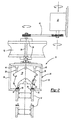
- the preferred embodiment of the dryer 10 of the present invention is shown and comprises a housing 12 (only partially illustrated) which defines a drying chamber 14.
- a conveyor 16 such as a lift and carry conveyor, extends through the housing chamber 14 and sequentially conveys industrial parts 18, such as engine blocks, from an inlet end 20 of the chamber 14 to an outlet end 22 of the chamber 14.
- a receiving frame 24 is rotatably mounted to the housing 12 by a shaft 26.
- Conventional bearing assemblies 28 are disposed between the housing 12 and shaft 26 to ensure free rotation of both the shaft 26 and its attached receiving frame 24.
- the receiving frame 24 generally comprises a pair of spaced apart and generally C-shaped bands 30 which are secured together by one or more cross members 32. As best shown in Figure 2, the C-shaped bands 30 have a downwardly facing opening 34 aligned with the conveyor 16 so that the conveyor 16, upon actuation, sequentially moves the industrial parts 18 into the interior of the receiving frame 24.
- the frame 24 further includes at least one, and more typically two to four location pins 36 at the bottom of the receiving frame 24. These location pins 36 register with location holes in the industrial part 18 when the industrial part 18 is moved into the interior of the receiving frame 24 by the conveyor 16. Consequently, on the down stroke of the conveyor 16, the conveyor 16 lowers the industrial part 18 onto the location pins 36 thus holding the part 18 against lateral movement.
- At least one, and preferably two locking pins 38 are mounted to the upper portion of the receiving frame 24.
- An actuator 40 is associated with each lock pin 38 to move the lock pin 38 between a lock position, in which the lock pin 38 engages the industrial part 18, and a release position, in which the lock pins 38 are spaced from the industrial part 18.
- the lock pins in their locked position Figure. 2
- the part 18 is fixed against movement relative to the receiving frame 24 between the lock pins 38 and location pins 36.
- a motor 42 such as an electric motor, is mechanically connected to the shaft 28 by any conventional means, such as a transmission belt 44.
- the motor 42 rotatably drives the shaft 26 with its attached frame 24.
- the conveyor 16 first vertically lifts the parts 18 so that the undried part 18 is aligned with the frame 24.
- the conveyor 16 then longitudinally moves the now dried part 18 from the interior of the receiving frame 24 and simultaneously longitudinally moves a new undried part 18 into the interior of the receiving frame 24.
- the conveyor 16 then lowers the part 18 on the location pins 36 and, after doing so, the conveyor 16 moves to its lower position, illustrated in solid line in Figures 1 and 2, and thus is downwardly spaced from the receiving frame 24.
- the actuators 40 are actuated thus moving the lock pins 38 to their locked position and fixing the part 18 against movement relative to the receiving frame 24.
- the motor 42 is then actuated, preferably for 10-180 seconds at 50-1500 rpm, thus rotatably driving the receiving frame 24 with its contained industrial part 18. In doing so, water, washing fluid, debris and the like are expelled outwardly from the part 18 by centripetal force caused by the rotation of the part 18 within the rotating frame 24.
- the motor 42 is deactivated thus halting the rotation of the frame 24.
- the actuators 40 then move the lock pins 38 to their release position so that, upon a subsequent actuation of the conveyor 16, the conveyor 16 removes the now dried part from the receiving frame 18 and simultaneously moves a new washed part 18 into the receiving frame 24 whereupon the above process is repeated.
- the present invention provides a simple and yet highly effective system for drying industrial parts.
- the industrial parts may be completely subsequently dried by subjecting the parts to a vacuum dryer.
Landscapes
- Engineering & Computer Science (AREA)
- Health & Medical Sciences (AREA)
- Life Sciences & Earth Sciences (AREA)
- Molecular Biology (AREA)
- Mechanical Engineering (AREA)
- General Engineering & Computer Science (AREA)
- Drying Of Solid Materials (AREA)
- Centrifugal Separators (AREA)
Claims (9)
- Trockner für Industrieteile, bestehend aus
einem Gehäuse (12),
einem Aufnahmerahmen (24),
einem Förderer (16), der Industrieteile (18) sequentiell durch das Gehäuse und in den Aufnahmerahmen fördert, worauf der Aufnahmerahmen eines der Industrieteile trägt,
dadurch gekennzeichnet, dass
der Trockner weiterhin einen Arretierungszapfen (38) aufweist, der am Aufnahmerahmen zwischen einer Arretierungsposition, in der der Arretierungszapfen in das Industrieteil eingreift und dessen Bewegung relativ zum Aufnahmerahmen verhindert, und einer Freigabeposition, in der der Arretierungszapfen vom Industrieteil beabstandet ist, so dass dessen Bewegung relativ zum Aufnahmerahmen ermöglicht wird, verstellbar befestigt ist,
ein Aktuator den Arretierungszapfen zwischen der Arretierungs- und der Freigabeposition selektiv verstellt,
eine Welle (26) am Gehäuse drehbar gelagert und am Aufnahmerahmen befestigt ist, und
ein Motor (42) mit der Welle mechanisch gekuppelt ist, so dass er bei Aktivierung den Aufnahmerahmen dreht. - Trockner nach Anspruch 1, bei dem der Förderer ein Hub- und Laufförderer ist.
- Trockner nach Anspruch 1 oder 2, bei dem der Motor ein Elektromotor ist.
- Trockner nach einem vorhergehenden Anspruch, weiterhin aufweisend wenigstens einen Positionierungszapfen (36), der am Rahmen befestigt ist und in eine Ausnehmung im Industrieteil eingreift.
- Trockner nach einem vorhergehenden Anspruch, bei dem das Industrieteil ein Motorblock ist.
- Trockner nach einem vorhergehenden Anspruch, bei dem der Motor bei Aktivierung den Aufnahmerahmen mit einer Geschwindigkeit von 50-1500 U/min dreht.
- Trockner nach einem vorhergehenden Anspruch, bei dem der Motor für eine Periode im Bereich von 10-180 Sekunden pro Industrieteil aktiviert wird.
- Trockner nach einem vorhergehenden Anspruch, bei dem der Aufnahmerahmen aus zwei beabstandeten C-förmigen Bändern besteht.
- Verfahren zum Trocknen von Industrieteilen in einem Trockner, dadurch gekennzeichnet, dass das Verfahren die folgenden Schritte umfasst:Verschieben mittels einer Transporteinrichtung wenigstens eines Industrieteils (118), um in einem Industrieteilaufnahmerahmen (24) getrocknet zu werden;Arretieren der wenigstens einen Teils bezüglich des Rahmens durch Verstellen eines Arretierungszapfens, der am Rahmen befestigt ist, in Eingriff mit dem Teil;Drehen des Rahmens bezüglich eines festen Gehäuses (12) des Trockners, um Fluid und/oder Rückstände von der wenigstens einem Teil durch Zentrifugalkraft zu entfernen.
Applications Claiming Priority (2)
| Application Number | Priority Date | Filing Date | Title |
|---|---|---|---|
| US758517 | 1985-07-26 | ||
| US09/758,517 US6381865B1 (en) | 2001-01-11 | 2001-01-11 | Spin dryer for industrial parts |
Publications (2)
| Publication Number | Publication Date |
|---|---|
| EP1223397A1 EP1223397A1 (de) | 2002-07-17 |
| EP1223397B1 true EP1223397B1 (de) | 2005-06-15 |
Family
ID=25052017
Family Applications (1)
| Application Number | Title | Priority Date | Filing Date |
|---|---|---|---|
| EP02250042A Revoked EP1223397B1 (de) | 2001-01-11 | 2002-01-04 | Schleudertrockner für industrielle Teile |
Country Status (7)
| Country | Link |
|---|---|
| US (1) | US6381865B1 (de) |
| EP (1) | EP1223397B1 (de) |
| AT (1) | ATE298073T1 (de) |
| CA (1) | CA2367721C (de) |
| DE (1) | DE60204603T2 (de) |
| ES (1) | ES2242827T3 (de) |
| MX (1) | MXPA02000400A (de) |
Families Citing this family (3)
| Publication number | Priority date | Publication date | Assignee | Title |
|---|---|---|---|---|
| US6511550B1 (en) * | 2001-11-29 | 2003-01-28 | Valiant Corporation | Method for cleaning and drying an industrial part |
| ES2284349B1 (es) * | 2005-09-20 | 2010-11-02 | Tecnopamic, S.A. | Maquina secadora-centrifugadora para cajas. |
| AT515324B1 (de) * | 2014-02-06 | 2016-05-15 | Tms Turnkey Mfg Solutions Gmbh | Schleuderreinigungsanlage und Verfahren zum Betreiben einer Schleuderreinigungsanlage |
Family Cites Families (16)
| Publication number | Priority date | Publication date | Assignee | Title |
|---|---|---|---|---|
| US1542929A (en) * | 1924-01-07 | 1925-06-23 | Woolrich Edward | Centrifugal drier |
| US3257732A (en) * | 1962-08-01 | 1966-06-28 | Gen Motors Corp | Drying of honeycomb metal structures |
| US3419429A (en) * | 1965-07-12 | 1968-12-31 | Jet Clean Company | Method and apparatus for cleaning engine blocks and the like |
| US3989537A (en) * | 1975-07-11 | 1976-11-02 | General Motors Corporation | Method and apparatus for vibration cleaning of workpieces such as engine blocks |
| US4064635A (en) * | 1976-06-17 | 1977-12-27 | Kuhl Henry Y | Apparatus for drying plastic trays |
| JPS5940943B2 (ja) * | 1981-07-17 | 1984-10-03 | 大阪ボビン株式会社 | チ−ズ脱水装置 |
| US4571850A (en) * | 1984-05-17 | 1986-02-25 | The Fluorocarbon Company | Centrifugal wafer processor |
| FR2591324B1 (fr) * | 1985-12-10 | 1989-02-17 | Recif Sa | Appareil pour le sechage unitaire des plaquettes de silicium par centrifugation |
| DE4140989A1 (de) * | 1991-12-12 | 1992-07-02 | Guenter Martin Landesberger | Kistentrocknungsanlage |
| US5339539A (en) * | 1992-04-16 | 1994-08-23 | Tokyo Electron Limited | Spindrier |
| US5421883A (en) * | 1994-03-15 | 1995-06-06 | Bowden Industries, Inc. | Industrial parts cleaning method and system |
| US5647140A (en) * | 1996-02-23 | 1997-07-15 | Hudspeth; Emmit | Produce centrifugal spin drying apparatus |
| DK173019B1 (da) * | 1996-04-24 | 1999-11-15 | Ken Maskinfabrik As | Anordning til afvaskning, skylning og tørring af genstande, såsom cateringvogne til anvendelse om bord på flyvemaskiner |
| JP3464133B2 (ja) * | 1997-12-25 | 2003-11-05 | 株式会社ニッパック物流 | 折畳み籠の遠心脱水装置 |
| DE19833416A1 (de) * | 1998-07-24 | 2000-01-27 | Guenter Landesberger | Kistentrocknungsanlage |
| JP3839220B2 (ja) * | 2000-05-11 | 2006-11-01 | 三鈴工機株式会社 | 容器遠心乾燥装置 |
-
2001
- 2001-01-11 US US09/758,517 patent/US6381865B1/en not_active Expired - Lifetime
-
2002
- 2002-01-04 AT AT02250042T patent/ATE298073T1/de not_active IP Right Cessation
- 2002-01-04 DE DE60204603T patent/DE60204603T2/de not_active Expired - Lifetime
- 2002-01-04 EP EP02250042A patent/EP1223397B1/de not_active Revoked
- 2002-01-04 ES ES02250042T patent/ES2242827T3/es not_active Expired - Lifetime
- 2002-01-11 CA CA002367721A patent/CA2367721C/en not_active Expired - Fee Related
- 2002-01-11 MX MXPA02000400A patent/MXPA02000400A/es active IP Right Grant
Also Published As
| Publication number | Publication date |
|---|---|
| ES2242827T3 (es) | 2005-11-16 |
| EP1223397A1 (de) | 2002-07-17 |
| MXPA02000400A (es) | 2004-10-15 |
| US6381865B1 (en) | 2002-05-07 |
| ATE298073T1 (de) | 2005-07-15 |
| DE60204603T2 (de) | 2006-05-11 |
| CA2367721A1 (en) | 2002-07-11 |
| DE60204603D1 (de) | 2005-07-21 |
| CA2367721C (en) | 2005-03-29 |
Similar Documents
| Publication | Publication Date | Title |
|---|---|---|
| JPH0528761Y2 (de) | ||
| JP2631961B2 (ja) | 振動分散機構付き遠心乾燥装置 | |
| EP1223397B1 (de) | Schleudertrockner für industrielle Teile | |
| EP0087649A1 (de) | Wasch- und Trockenmaschine für Obst und/oder Gemüse | |
| KR101833507B1 (ko) | 해태 건조기 | |
| JPH0839024A (ja) | 洗浄装置 | |
| JP3619164B2 (ja) | 遠心分離機及びその運転方法 | |
| JP2001041650A (ja) | 遠心分離乾燥処理装置 | |
| KR102228139B1 (ko) | 수직방향으로 연속공정이 이루어지는 도금체 건조장치 | |
| US5187831A (en) | Parts washer | |
| CA2538945A1 (en) | Method for cleaning an industrial part | |
| KR200227762Y1 (ko) | 공작물 세척기 | |
| JPH06277393A (ja) | 洗濯物の回転脱水機 | |
| JPH0810722A (ja) | 洗浄装置 | |
| JP2009082808A (ja) | 遠心分離機 | |
| EP1164216A1 (de) | Sicherheitsvorrichtung für eine Waschmaschine | |
| CN221811440U (zh) | 一种机械加工沥水装置 | |
| CN222031172U (zh) | 一种方便面块成型装置 | |
| CN222396956U (zh) | 一种冻干果蔬脱水装置 | |
| JPH1085491A (ja) | 石油系洗濯脱水乾燥機及び被洗濯物の移送方法 | |
| JP3265357B2 (ja) | 部品の洗浄・乾燥装置 | |
| JPH06194038A (ja) | 樹脂製通函乾燥装置 | |
| RU2231168C1 (ru) | Устройство для обработки полупроводниковых пластин | |
| JP2002028398A (ja) | 洗濯物乾燥機における洗濯物の振動装置 | |
| JPH06134410A (ja) | 洗浄装置 |
Legal Events
| Date | Code | Title | Description |
|---|---|---|---|
| PUAI | Public reference made under article 153(3) epc to a published international application that has entered the european phase |
Free format text: ORIGINAL CODE: 0009012 |
|
| AK | Designated contracting states |
Kind code of ref document: A1 Designated state(s): AT BE CH CY DE DK ES FI FR GB GR IE IT LI LU MC NL PT SE TR |
|
| AX | Request for extension of the european patent |
Free format text: AL;LT;LV;MK;RO;SI |
|
| 17P | Request for examination filed |
Effective date: 20021217 |
|
| AKX | Designation fees paid |
Designated state(s): AT BE CH CY DE DK ES FI FR GB GR IE IT LI LU MC NL PT SE TR |
|
| 17Q | First examination report despatched |
Effective date: 20040120 |
|
| GRAP | Despatch of communication of intention to grant a patent |
Free format text: ORIGINAL CODE: EPIDOSNIGR1 |
|
| GRAS | Grant fee paid |
Free format text: ORIGINAL CODE: EPIDOSNIGR3 |
|
| GRAA | (expected) grant |
Free format text: ORIGINAL CODE: 0009210 |
|
| AK | Designated contracting states |
Kind code of ref document: B1 Designated state(s): AT BE CH CY DE DK ES FI FR GB GR IE IT LI LU MC NL PT SE TR |
|
| PG25 | Lapsed in a contracting state [announced via postgrant information from national office to epo] |
Ref country code: FI Free format text: LAPSE BECAUSE OF FAILURE TO SUBMIT A TRANSLATION OF THE DESCRIPTION OR TO PAY THE FEE WITHIN THE PRESCRIBED TIME-LIMIT Effective date: 20050615 Ref country code: CH Free format text: LAPSE BECAUSE OF FAILURE TO SUBMIT A TRANSLATION OF THE DESCRIPTION OR TO PAY THE FEE WITHIN THE PRESCRIBED TIME-LIMIT Effective date: 20050615 Ref country code: LI Free format text: LAPSE BECAUSE OF FAILURE TO SUBMIT A TRANSLATION OF THE DESCRIPTION OR TO PAY THE FEE WITHIN THE PRESCRIBED TIME-LIMIT Effective date: 20050615 Ref country code: AT Free format text: LAPSE BECAUSE OF FAILURE TO SUBMIT A TRANSLATION OF THE DESCRIPTION OR TO PAY THE FEE WITHIN THE PRESCRIBED TIME-LIMIT Effective date: 20050615 Ref country code: TR Free format text: LAPSE BECAUSE OF FAILURE TO SUBMIT A TRANSLATION OF THE DESCRIPTION OR TO PAY THE FEE WITHIN THE PRESCRIBED TIME-LIMIT Effective date: 20050615 |
|
| REG | Reference to a national code |
Ref country code: GB Ref legal event code: FG4D Ref country code: CH Ref legal event code: EP |
|
| REF | Corresponds to: |
Ref document number: 60204603 Country of ref document: DE Date of ref document: 20050721 Kind code of ref document: P |
|
| REG | Reference to a national code |
Ref country code: IE Ref legal event code: FG4D |
|
| REG | Reference to a national code |
Ref country code: SE Ref legal event code: TRGR |
|
| PG25 | Lapsed in a contracting state [announced via postgrant information from national office to epo] |
Ref country code: GR Free format text: LAPSE BECAUSE OF FAILURE TO SUBMIT A TRANSLATION OF THE DESCRIPTION OR TO PAY THE FEE WITHIN THE PRESCRIBED TIME-LIMIT Effective date: 20050915 Ref country code: DK Free format text: LAPSE BECAUSE OF FAILURE TO SUBMIT A TRANSLATION OF THE DESCRIPTION OR TO PAY THE FEE WITHIN THE PRESCRIBED TIME-LIMIT Effective date: 20050915 |
|
| REG | Reference to a national code |
Ref country code: ES Ref legal event code: FG2A Ref document number: 2242827 Country of ref document: ES Kind code of ref document: T3 |
|
| PG25 | Lapsed in a contracting state [announced via postgrant information from national office to epo] |
Ref country code: PT Free format text: LAPSE BECAUSE OF FAILURE TO SUBMIT A TRANSLATION OF THE DESCRIPTION OR TO PAY THE FEE WITHIN THE PRESCRIBED TIME-LIMIT Effective date: 20051124 |
|
| REG | Reference to a national code |
Ref country code: CH Ref legal event code: PL |
|
| PG25 | Lapsed in a contracting state [announced via postgrant information from national office to epo] |
Ref country code: IE Free format text: LAPSE BECAUSE OF NON-PAYMENT OF DUE FEES Effective date: 20060104 |
|
| PG25 | Lapsed in a contracting state [announced via postgrant information from national office to epo] |
Ref country code: MC Free format text: LAPSE BECAUSE OF NON-PAYMENT OF DUE FEES Effective date: 20060131 Ref country code: LU Free format text: LAPSE BECAUSE OF NON-PAYMENT OF DUE FEES Effective date: 20060131 |
|
| PLBI | Opposition filed |
Free format text: ORIGINAL CODE: 0009260 |
|
| PLAX | Notice of opposition and request to file observation + time limit sent |
Free format text: ORIGINAL CODE: EPIDOSNOBS2 |
|
| ET | Fr: translation filed | ||
| 26 | Opposition filed |
Opponent name: DUERR ECOCLEAN GMBH Effective date: 20060315 |
|
| NLR1 | Nl: opposition has been filed with the epo |
Opponent name: DUERR ECOCLEAN GMBH |
|
| PLAF | Information modified related to communication of a notice of opposition and request to file observations + time limit |
Free format text: ORIGINAL CODE: EPIDOSCOBS2 |
|
| REG | Reference to a national code |
Ref country code: IE Ref legal event code: MM4A |
|
| PLBB | Reply of patent proprietor to notice(s) of opposition received |
Free format text: ORIGINAL CODE: EPIDOSNOBS3 |
|
| RDAF | Communication despatched that patent is revoked |
Free format text: ORIGINAL CODE: EPIDOSNREV1 |
|
| RDAD | Information modified related to despatch of communication that patent is revoked |
Free format text: ORIGINAL CODE: EPIDOSCREV1 |
|
| APBP | Date of receipt of notice of appeal recorded |
Free format text: ORIGINAL CODE: EPIDOSNNOA2O |
|
| APAH | Appeal reference modified |
Free format text: ORIGINAL CODE: EPIDOSCREFNO |
|
| APAH | Appeal reference modified |
Free format text: ORIGINAL CODE: EPIDOSCREFNO |
|
| APBQ | Date of receipt of statement of grounds of appeal recorded |
Free format text: ORIGINAL CODE: EPIDOSNNOA3O |
|
| PG25 | Lapsed in a contracting state [announced via postgrant information from national office to epo] |
Ref country code: CY Free format text: LAPSE BECAUSE OF FAILURE TO SUBMIT A TRANSLATION OF THE DESCRIPTION OR TO PAY THE FEE WITHIN THE PRESCRIBED TIME-LIMIT Effective date: 20050615 |
|
| PGFP | Annual fee paid to national office [announced via postgrant information from national office to epo] |
Ref country code: NL Payment date: 20090125 Year of fee payment: 8 |
|
| PGFP | Annual fee paid to national office [announced via postgrant information from national office to epo] |
Ref country code: BE Payment date: 20090126 Year of fee payment: 8 |
|
| PGFP | Annual fee paid to national office [announced via postgrant information from national office to epo] |
Ref country code: ES Payment date: 20100129 Year of fee payment: 9 |
|
| PGFP | Annual fee paid to national office [announced via postgrant information from national office to epo] |
Ref country code: FR Payment date: 20100210 Year of fee payment: 9 |
|
| BERE | Be: lapsed |
Owner name: *VALIANT CORP. Effective date: 20100131 |
|
| REG | Reference to a national code |
Ref country code: NL Ref legal event code: V1 Effective date: 20100801 |
|
| PG25 | Lapsed in a contracting state [announced via postgrant information from national office to epo] |
Ref country code: NL Free format text: LAPSE BECAUSE OF NON-PAYMENT OF DUE FEES Effective date: 20100801 |
|
| PGFP | Annual fee paid to national office [announced via postgrant information from national office to epo] |
Ref country code: SE Payment date: 20100129 Year of fee payment: 9 |
|
| PG25 | Lapsed in a contracting state [announced via postgrant information from national office to epo] |
Ref country code: BE Free format text: LAPSE BECAUSE OF NON-PAYMENT OF DUE FEES Effective date: 20100131 |
|
| PG25 | Lapsed in a contracting state [announced via postgrant information from national office to epo] |
Ref country code: IT Free format text: LAPSE BECAUSE OF NON-PAYMENT OF DUE FEES Effective date: 20100104 |
|
| APBU | Appeal procedure closed |
Free format text: ORIGINAL CODE: EPIDOSNNOA9O |
|
| PGFP | Annual fee paid to national office [announced via postgrant information from national office to epo] |
Ref country code: DE Payment date: 20110202 Year of fee payment: 10 |
|
| PGFP | Annual fee paid to national office [announced via postgrant information from national office to epo] |
Ref country code: GB Payment date: 20110126 Year of fee payment: 10 |
|
| PGRI | Patent reinstated in contracting state [announced from national office to epo] |
Ref country code: IT Effective date: 20110616 |
|
| RDAG | Patent revoked |
Free format text: ORIGINAL CODE: 0009271 |
|
| STAA | Information on the status of an ep patent application or granted ep patent |
Free format text: STATUS: PATENT REVOKED |
|
| 27W | Patent revoked |
Effective date: 20071024 |
|
| GBPR | Gb: patent revoked under art. 102 of the ep convention designating the uk as contracting state |
Effective date: 20071024 |
|
| REG | Reference to a national code |
Ref country code: DE Ref legal event code: R107 Ref document number: 60204603 Country of ref document: DE Effective date: 20111020 |
|
| REG | Reference to a national code |
Ref country code: SE Ref legal event code: ECNC |
|
| PGFP | Annual fee paid to national office [announced via postgrant information from national office to epo] |
Ref country code: IT Payment date: 20120112 Year of fee payment: 11 |