EP1220786B1 - Förderstreckenanordnung in einer füllstation - Google Patents
Förderstreckenanordnung in einer füllstation Download PDFInfo
- Publication number
- EP1220786B1 EP1220786B1 EP00975856A EP00975856A EP1220786B1 EP 1220786 B1 EP1220786 B1 EP 1220786B1 EP 00975856 A EP00975856 A EP 00975856A EP 00975856 A EP00975856 A EP 00975856A EP 1220786 B1 EP1220786 B1 EP 1220786B1
- Authority
- EP
- European Patent Office
- Prior art keywords
- filling
- container
- belt
- conveyor
- assembly
- Prior art date
- Legal status (The legal status is an assumption and is not a legal conclusion. Google has not performed a legal analysis and makes no representation as to the accuracy of the status listed.)
- Expired - Lifetime
Links
Images

Classifications
-
- B—PERFORMING OPERATIONS; TRANSPORTING
- B65—CONVEYING; PACKING; STORING; HANDLING THIN OR FILAMENTARY MATERIAL
- B65B—MACHINES, APPARATUS OR DEVICES FOR, OR METHODS OF, PACKAGING ARTICLES OR MATERIALS; UNPACKING
- B65B43/00—Forming, feeding, opening or setting-up containers or receptacles in association with packaging
- B65B43/42—Feeding or positioning bags, boxes, or cartons in the distended, opened, or set-up state; Feeding preformed rigid containers, e.g. tins, capsules, glass tubes, glasses, to the packaging position; Locating containers or receptacles at the filling position; Supporting containers or receptacles during the filling operation
- B65B43/52—Feeding or positioning bags, boxes, or cartons in the distended, opened, or set-up state; Feeding preformed rigid containers, e.g. tins, capsules, glass tubes, glasses, to the packaging position; Locating containers or receptacles at the filling position; Supporting containers or receptacles during the filling operation using roller-ways or endless conveyors
Definitions
- the invention relates to an arrangement of a conveyor line for conveyed on the conveyor line, with articles or Bulk material to be filled in a filling station via a hopper, in the filling position located container according to the preamble of claim 1.
- Such Arrangement is known from DE-A-19 812 248.
- the invention relates especially that part of a picking machine transfer station, which feeds the shipping containers to the filling station, for the duration of the product or product handover Positioned below the filling or transfer funnels and then discharged from the filling station again.
- the containers are in the area the picking machine transfer over a constantly running Conveyor belt moves.
- the isolation of the incoming containers is by a arranged in front of the transfer station clamping device accomplished, which the respective foremost container recorded and continue to run until shortly before the filling station leaves.
- a second clamping device Just below the first clamp downstream filling or transfer funnel is located on both sides of the conveyor belt, a second clamping device, the the incoming container detected and him until the completion of the Holding the filling in the correct position.
- the filled container is released, from continuously driven conveyor belt frictionally entrained and off transported to the transfer area.
- the container change time and thus in many cases the throughput of the whole Picking system thus depend on the speed with which the containers on the conveyor belt frictionally be further clocked.
- the object of the invention is to provide an arrangement of the aforementioned type, which by means of simple means a perfect and effective filling one in the filling position located exactly positioned container allows and, if necessary, faster indexing the container is allowed in the area of the filling station.
- driver plates provided in the circulating toothed belt or chain drive attached at an equal distance, in particular, are suspended, with the distance of the Tank width in the conveying direction corresponds.
- the driver plates are in particular thin-walled in itself stable spring steel plates, preferably with a thickness of about 0.7mm.
- the driver plates have in particular slots on the top side preferably in the vertical direction, which the elasticity increase or create spring action when in fact an obstacle in the trajectory, which is then overcome becomes.
- the toothed belt or chain drive can be particularly advantageous Development of the invention with a stationary vertical Container guide wall formed in the conveying direction be, which in particular between upper and lower chord of Zahnriemen- or chain drive is arranged, wherein the container guide wall, optionally together with the upper belt, In the area of the filling opening, a filling shaft wall in the conveying direction formed.
- the hopper itself can be used as a buffer funnel or with a be formed separate buffer funnel, which is a the filling opening closing and opening horizontal slide contains, wherein preferably formed in two parts Horizontal slide only at one positioned in the filling position Container open and otherwise closed is.
- an emergency running device for input and output the container to be filled especially in case of failure the operation of the toothed belt or chain drive provided.
- the emergency facility comprises two lateral ones on each side Stopper, through which on a continuously driven Conveyor belt through the filling station running container in the filling position and in the upstream waiting position preferably positionable by lateral friction and are releasable.
- the sensors of the actuator of the or the toothed belt or Chain drives and possibly existing emergency running device includes in particular five light barriers, one Inductive transmitter and a scanner, being on the input side the filling station in the conveyor line another stopper is provided for separating the container, which in the Movement path of the subsidized container are provided or can release the movement path of the conveyed container.
- the entire system can be made so that a single continuous conveyor line before, in and after the filling station preferably designed as a belt conveyor or belt drive is.
- the conveyor line can be located in the area of the circulating toothed belt or chain drive be interrupted and a separate Have belt conveyor or belt drive with its own drive.
- the upstream of the toothed belt or chain drive input side Conveyor line can be a conveyor belt, a zero pressure Accumulation roller conveyor or a struckruck21maschinerollenbahn be.
- the belt conveyor or belt drive can in the area of the filling position also have a stationary upper sliding surface, wherein the belt conveyor or belt drive in the region of the sliding surface formed over pulleys down parallel offset can be.
- a container change preferably accelerated and in particular exactly be performed.
- the container to be filled is hereby positioned exactly in the filling position and filled easily.
- the containers become positive by a flat driver under a transfer funnel (Puffertrichter) very quickly motiftaktet.
- a transfer funnel Puffertrichter
- h or h ' transfer funnel
- This is erfindungsgeäß achieved in that a shaft-like training from the opening of the transfer funnel to the opening the container is formed, regardless of the Height of a container.
- the opening becomes transverse to the conveying direction formed by the driver plates or aprons themselves, which together with side baffles the total opening determine.
- the gauge is of the so-called indexer on the containers or boxes, that seen in about the front and rear in the conveying direction only a total game of approx. 6 mm total game exists.
- the container or carton thus has only in the conveying direction a total game of about 6mm.
- the usual Products may have approximately 12mm to 15mm minimum size no product will fall off during filling.
- the indexer has a toothed belt or chain drive left and right side of the container with vertical Axes up.
- This drive is by a common Chain or a common double toothed timing belt driven by a single servomotor or actuator.
- On each toothed belt or chain drive are in particular six drive plates preferably made of spring steel, which represent about half the container width.
- the sensor system consists of five photoelectric sensors, an inductive sensor and a scanner. Furthermore, there is a stopper to to let the containers retract occasionally. About that There are also two more stoppers that will be included in any event Emergency operation, in which the driver plates partially removed and are no longer in function, the position of Determine container.
- the driver plates engage behind on the input side of the Fill the containers and allow if necessary standstill a great acceleration of the containers, under the engagement of a driver plate on the Container rear side, which faces away from the conveying direction. Because the positioning of the container is form-fitting, and not by clamping the container as in the prior art not only can comparatively stable containers such as plastic, but also made of containers more sensitive material, such as cardboard, used according to the invention.
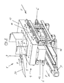
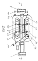
- FIG. 1 includes a not interesting here Picking system with, for example, high-speed turning machines, Article storage shelves, stacker cranes, etc. among others also an arrangement 1 of a conveyor line 2 for (shipping) container or over cartons from a container storage station a container shipping station with an intermediate Filling station 4, in the picked item 3 or bulk goods via a hopper 5 in one on the conveyor line 2 promoted, arranged under the hopper, open at the top Container 10, 11, 12 are filled, as in particular can be seen from Figure 1.
- a conveyor line 2 for (shipping) container or over cartons from a container storage station a container shipping station with an intermediate Filling station 4, in the picked item 3 or bulk goods via a hopper 5 in one on the conveyor line 2 promoted, arranged under the hopper, open at the top Container 10, 11, 12 are filled, as in particular can be seen from Figure 1.
- the article 3 or the bulk material will be over an oblique central conveyor belt 30 the hopper 5 in the arrow direction P supplied.
- the conveyor line 2 which in principle, for example, a continuous conveyor belt, a driving roller conveyor or a S Heck roller conveyor may be in the immediate area before, in and after the filling station 4 right and left, i. on both sides of the conveyor belt or the like a toothed belt or Chain drive 6 with a common dynamic drive in the form of an intermittent actuator 7, which a slip-free accelerated continuation of one or more Container concerned, located in the immediate area of Filling station 4 are located.
- each of the side toothed belts has or Chain drive 6 from each other equally spaced container-Mitêtissen 8, in the embodiment six, through which on the conveyor line 2 incoming open-topped container 10, 11, 12 isolated both in the filling position and after accelerated filling from the filling position clocked and the output side of the conveyor line 2 are fed again.
- the revolving toothed belt or chain drive 6 on both Broad sides of the conveyor line is axially symmetrical to the conveyor line designed such that associated drive plates 8 on each side in the conveying direction F of the container at the same height or length.
- the conveyor line 2 has before the toothed belt or chain drive 6 a stopper 21, which in the trajectory of subsidized container are made or the trajectory the subsidized container can release.
- the arrangement of the conveyor line 2 is made such that in particular through in the filling position, adjacent, extending transversely to the conveying direction F driver plates 8 a Gearschachtwand between hopper 5 and a container to be filled is formed.
- the six driver plates 8 are in the associated circumferential Toothed belt drive at the same distance in particular hung, wherein the distance of the container width in the conveying direction F corresponds.
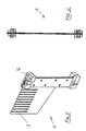
- the driver plates 8 are thin-walled spring steel plates and have slots 9 on the upper side in the vertical direction.
- the driver plate 8 is shown in detail in Figures 5 and 6 shown. It has a verikales fastening tape with top bracket 26 for attachment to a Timing belt fastening point 25, in particular on the upper strand 14 the associated toothed belt drive 6, while the vertical fastening strap on the underside of the lower strand 15 in exact vertical Alignment of a Mitnhemerplatte 8 also attached or supported laterally.
- each other opposite toothed belt drives 6 with vertical axes 13 and with upper and lower chord 14, 15 on both sides of the conveyor line 2 provided, wherein the driver plates 8 approximately half are as wide as the container width transverse to the conveying direction F and both drives 6 driven by a common actuator 7, in particular clocked are.
- Each toothed belt drive 6 is a stationary vertical Container guide wall 16 is formed in the conveying direction F, which in particular between the upper and lower chords 14, 15 of the Toothed belt drive 6 is arranged, wherein the container guide wall 16, optionally together with the upper flange 14, In the area of the filling opening, a filling shaft wall in the conveying direction F trains.
- the hopper 5 can be used as a buffer funnel or with a separate Buffer funnel 17 may be formed, which has a the filling opening closing and opening horizontal slide Contains 18, wherein the two-part formed horizontal slide only with one positioned in the filling position Container 11 is opened and otherwise closed.
- the emergency facility comprises two lateral ones on each side Stopper 19, 20, through which on a continuously driven Conveyor belt through the filling station 4 running container 10, 11, 12 in the filling position and in the upstream Waiting position preferably by lateral friction can be positioned and released.
- the sensor system of the actuator 7 of the toothed belt drive 6 comprises five photoelectric sensors LS1, LS2, LS3, LS4, LS5, one inductive sensor 23 and a scanner 22 according to Figure 7, wherein on the input side of the filling station in the conveying path of Stopper 21, the separation of the containers 10, 11, 12 concerned.
- FIG. 1 it is a so-called indexer with a built-up indexer Buffer funnel provided.
- the central band promotes or the riser of the central band a product heap, at the transfer point in the boxes or in the Container is handed over.
- the function of the buffer funnel here in particular provides a two-part slider, wherein both slide halves are opened as soon as the carton is positioned below. The advantage is that you can during of the positioning process of the carton the funnel over the Sliders can already fill. Is the carton positioned the slide opens and the products fall down in the postitioned container.
- indexer here is that even if the boxes or containers are the same height, a distance held between the slider halves and the cardboard top can be, e.g. 100mm, so supernatant products not to be clamped when walking the slider halves.
- the indexer is completely empty.
- the box moves to the light barrier LS1 and drives through to the time standing at this time Mit supportiveplatte 8, right, according to Figure 7.
- the Mit supportiveplatte additionallygetaktet on the position of in FIG 7 illustrated driver plate 8, left, i. in the filling position, positively entrained the container and at the same time read.
- a second following container is now driving through the light barriers LS1 and LS2 through, until again to Driver plate 8, right, and occupies the light barrier LS3. If a third container comes, must - by the fact that the light barriers LS3 and LS4 are occupied - the light barrier LS1 activate the stopper 21, and the container remains in front of the Indexer stand.
- the light barrier LS2 is only a control light barrier.
- the indexer goes to error ("Dumping the tanks"), otherwise in a further transport of the container over the Indexer a "crash" would come about.
- the indexer clocks by one Driving position continues.
- the container reaches the Waiting position in the filling position.
- the filled container drives out, and gets on the output side conveyor line 2 discharged to a packaging station.
- the light barrier LS5 is also a control light barrier, which controls the outgoing container.
- the indexer may not switch again until this area is cleared is.
- the inductive sensor directly detects the driver plates, whereby the following function is fulfilled: that the drive via a servo motor and a corresponding Ramp, in particular an asymmetrical sine square ramp, is driven.
- the inductive sensor is aimed directly at the driver plate, but they are not really related to the beginning and the end is, i. each time a file is indexed, it is referenced once, and the servo motor steers over its entered ramp and counting clocks the position of the drive plates at.
- the indexer is out of order. Corresponding driver plates in the pass must be dismantled to clear passage to ensure. Control is everything like at Normal Bet.
- the light barrier LS3 and the light barrier LS4 are then simultaneously trigger photocell for the Stopper.
- the forwarding of the container is done by friction over the corresponding continuous conveyor belt.
- the indexer together with its inductive sensor is completely out of operation.
- the throughput is correspondingly lower, because not form-fitting and clocked through with high acceleration can.
Landscapes
- Engineering & Computer Science (AREA)
- Microelectronics & Electronic Packaging (AREA)
- Mechanical Engineering (AREA)
- Basic Packing Technique (AREA)
- Control Of Conveyors (AREA)
- Filling Or Emptying Of Bunkers, Hoppers, And Tanks (AREA)
- Container Filling Or Packaging Operations (AREA)
- Attitude Control For Articles On Conveyors (AREA)
- Belt Conveyors (AREA)
Description
- Fig. 1
- in einer schematischen perspektivischen Ansicht eine Anordnung einer Förderstrecke einer Kommissionieranlage im Bereich einer Füllstation, in welcher offene auf der Förderstrecke geförderte Behälter mit Artikeln bzw. Produkten befüllt werden und anschließend einer Versandstation zugeführt werden können, wobei seitlich vom Durchlauf der Behälter bzw. seitlich von der Förderstrecke jeweils ein doppelter Zahnriementrieb mit Vertikalachsen mit Mitnehmerplatten vorgesehen ist, die von einem gemeinsamen Stellantrieb über einen Zahnriemen angetrieben sind,
- Fig. 2
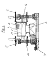
- die Anordnung nach Figur 1 in einer schematischen perspektivischen Ansicht, wobei der Fülltrichter und der Puffertrichter weggelassen sind,
- Fig. 3
- eine schematische Draufsicht auf die Anordnung nach Figur 2 unter Weglassung der Behälter,
- Fig. 4
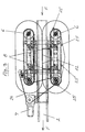
- eine schematische Stirnansicht auf die Anordnung nach Figur 2, wobei auf der linken Seite die Mitnehmerplatte des linken doppelten Zahnriementriebs weggelassen ist,
- Fig. 5
- eine Mitnehmerplatte in einer perspektivischen Ansicht von schräg oben,
- Fig. 6
- die Mitnehmereplatte nach Figur 5 in einer Stirnansicht, und
- Fig. 7
- die Anordnung nach den Figuren 1 bis 4 mit eingangs- und ausgangsseitigem Anschluß einer Förderstrecke sowie mit Darstellung von Lichtschranken.
Claims (14)
- Anordnung (1) einer Förderstrecke (2) für auf der Förderstrecke geförderte, mit Artikeln (3) oder Schüttgut in einer Füllstation (4) über einen Fülltrichter (5) zu befüllende, sich in der Füllstellung befindliche Behälter (10, 11, 12), wobei
die Förderstrecke (2) im unmittelbaren Bereich vor, in und/oder nach der Füllstation (4) zumindest auf einer Seite einen umlaufenden Zahnriemen- oder Kettentrieb (6) mit eigenem intermittierenden Stellantrieb (7) und voneinander beabstandeten Behälter-Mitnehmerplatten (8) aufweist, welche mit auf der Förderstrecke (2) ankommenden oben offenen Behältern (10, 11, 12) in einen formschlüssigen Eingriff bringbar sind und durch welche die Behälter vereinzelt sowohl in die Füllstellung als auch nach einem Befüllen aus der Füllstellung vorzugsweise beschleunigt getaktet und gegebenenfalls ausgangsseitig der Förderstrecke (2) wieder zugeführt werden können, dadurch gekennzeichnet, daß in der Füllstellung befindliche, benachbarte, sich quer zur Förderrichtung (F) erstreckende Mitnehmerplatten (8) eine Füllschachtwand zwischen Fülltrichter (5) und einem zu befüllenden Behälter ausbilden. - Anordnung nach Anspruch 1,
dadurch gekennzeichnet, daß vorzugsweise sechs Mitnehmerplatten (8) vorgesehen und im umlaufenden Zahnriemen- oder Kettentrieb in einem gleichen Abstand befestigt, insbesondere eingehängt, sind, wobei der Abstand der Behälterbreite in Förderrichtung (F) entspricht. - Anordnung nach Anspruch 1 oder 2,
dadurch gekennzeichnet, daß die Mitnehmerplatten (8) dünnwandige Federstahlplatten sind. - Anordnung nach einem der Ansprüche 1 bis 3,
dadurch gekennzeichnet, daß die Mitnehmerplatten (8) oberseitig Schlitze (9) vorzugweise in Vertikalrichtung aufweisen. - Anordnung nach einem der Ansprüche 1 bis 4,
dadurch gekennzeichnet, daß zwei gleiche, spiegelbildlich aufgebaute, einander gegenüberliegende Zahnriemen- oder Kettentriebe (6) mit Vertikalachsen (13) sowie mit Ober- und Untergurt (14, 15) beidseits der Förderstrecke (2) vorgesehen sind, wobei die Mitnehmerplatten (8) etwa halb so breit sind wie die Behälterbreite quer zur Förderrichtung (F) und beide Triebe (6) von einem gemeinsamen Stellantrieb (7) angetrieben, insbesondere getaktet, sind. - Anordnung nach einem der Ansprüche 1 bis 5,
dadurch gekennzeichnet, daß der Zahnriemen- oder Kettentrieb (6) mit einer stationären vertikalen Behälterführungswand (16) in Förderrichtung (F) ausgebildet ist, welche insbesondere zwischen Ober- und Untergurt (14, 15) des Zahnriemen- oder Kettentriebs (6) angeordnet ist, wobei die Behälterführungswand (16), gegebenenfalls zusammen mit dem Obergurt (14), im Bereich der Füllöffung eine Füllschachtwand in Förderrichtung (F) ausbildet. - Anordnung nach einem der Ansprüche 1 bis 6,
dadurch gekennzeichnet, daß der Fülltrichter (5) als Puffertrichter oder mit einem separaten Puffertrichter (17) ausgebildet ist, welcher einen die Füllöffnung verschließenden und öffenbaren Horizontalschieber (18) enthält, wobei der vorzugsweise zweiteilig ausgebildete Horizontalschieber nur bei einem in der Füllstellung positionierten Behälter (11) geöffnet und ansonsten geschlossen ist. - Anordnung nach einem der Ansprüche 1 bis 7,
dadurch gekennzeichnet, daß eine Notlauf-Einrichtung zum Ein- und Austakten der zu befüllenden Behälter (10, 11, 12) insbesondere bei Ausfall des Betriebs des Zahnriemen- oder Kettentriebs (6) vorgesehen ist. - Anordnung nach Anspruch 8,
dadurch gekennzeichenet,
daß die Notlauf-Einrichtung auf jeder Seite zwei seitliche Stopper (19, 20) umfaßt, durch welche auf einem kontinuierlich angetriebenen Förderband durch die Füllstation (4) laufende Behälter (10, 11, 12) in der Füllstellung sowie in der vorgelagerten Wartestellung vorzugsweise durch seitlichen Reibschluß positionierbar und freigebbar sind. - Anordnung nach einem der Ansprüche 1 bis 9,
dadurch gekennzeichnet, daß die Sensorik des Stellantriebs (7) des oder der Zahnriemen- oder Kettentriebe (6) sowie der gegebenenfalls vorhandenen Notlauf-Einrichtung fünf Lichtschranken (LS1, LS2, LS3, LS4, LS5), einen Induktivgeber (23) und einen Scanner (22) umfaßt, wobei auf der Eingangsseite der Füllstation in der Förderstrecke ein weiterer Stopper (21) zum Vereinzeln der Behälter (10, 11, 12) vorgesehen ist, welcher in die Bewegungsbahn der geförderten Behälter gestellt werden bzw. die Bewegungsbahn der geförderten Behälter freigeben kann - Anordnung nach einem der Ansprüche 1 bis 10,
dadurch gekennzeichnet, daß eine einzige durchgehende Förderstrecke (2) vor, in und nach der Füllstation (4) vorzugsweise als Gurtförderer bzw. Riementrieb vorgesehen ist. - Anordnung nach Anspruch 11,
dadurch gekennzeichnet, daß die Förderstrecke (2) im Bereich des umlaufenden Zahnriemen- oder Kettentriebs (6) unterbrochen ist und einen separaten Gurtförderer bzw. Riementrieb mit einem eigenen Antrieb aufweist. - Anordnung nach Anspruch 12,
dadurch gekennzeichnet, daß die vor dem Zahnriemen- oder Kettentrieb (6) gelegene eingangsseitige Förderstrecke (2) ein Förderband, eine staudrucklose Staurollenbahn oder eine staudruckbehaftete Treibrollenbahn ist. - Anordnung nach Anspruch 12 oder 13,
dadurch gekennzeichnet, daß der Gurtförderer bzw. Riementrieb im Bereich der Füllstellung eine stationäre obere Gleitfläche besitzt, wobei der Gurtförderer bzw. Riementrieb im Bereich der Gleitfläche über Umlenkrollen nach unten parallelversetzt ausgebildet sein kann.
Applications Claiming Priority (3)
| Application Number | Priority Date | Filing Date | Title |
|---|---|---|---|
| DE19949440A DE19949440A1 (de) | 1999-10-14 | 1999-10-14 | Förderstreckenanordnung in einer Füllstation |
| DE19949440 | 1999-10-14 | ||
| PCT/EP2000/009794 WO2001026972A1 (de) | 1999-10-14 | 2000-10-06 | Förderstreckenanordnung in einer füllstation |
Publications (2)
| Publication Number | Publication Date |
|---|---|
| EP1220786A1 EP1220786A1 (de) | 2002-07-10 |
| EP1220786B1 true EP1220786B1 (de) | 2003-08-06 |
Family
ID=7925548
Family Applications (1)
| Application Number | Title | Priority Date | Filing Date |
|---|---|---|---|
| EP00975856A Expired - Lifetime EP1220786B1 (de) | 1999-10-14 | 2000-10-06 | Förderstreckenanordnung in einer füllstation |
Country Status (6)
| Country | Link |
|---|---|
| US (1) | US6622851B1 (de) |
| EP (1) | EP1220786B1 (de) |
| AT (1) | ATE246633T1 (de) |
| DE (3) | DE19949440A1 (de) |
| ES (1) | ES2203531T3 (de) |
| WO (1) | WO2001026972A1 (de) |
Families Citing this family (13)
| Publication number | Priority date | Publication date | Assignee | Title |
|---|---|---|---|---|
| DE19949440A1 (de) * | 1999-10-14 | 2001-05-03 | Knapp Logistik Automation | Förderstreckenanordnung in einer Füllstation |
| US7175516B2 (en) * | 2002-01-18 | 2007-02-13 | Memco | Poultry processing hub and belt assembly |
| US6793067B1 (en) * | 2003-06-30 | 2004-09-21 | Emhart Glass S.A. | Container inspection machine |
| US6915894B2 (en) * | 2003-06-30 | 2005-07-12 | Emhart Glass S.A. | Container inspection machine |
| DE10356073B4 (de) * | 2003-12-01 | 2007-02-15 | Sig Technology Ltd. | Verfahren und Vorrichtung zum Befüllen von oben offenen Getränkebehältern |
| CN100460160C (zh) * | 2006-04-03 | 2009-02-11 | 四川大学 | 同步带驱动的自适应误差消除式自动取物装置 |
| DE102008023541A1 (de) * | 2008-05-14 | 2009-12-03 | Kannenberg, Hartmut | Gerät zum Transport per Reibschluss |
| DE102009027280A1 (de) * | 2009-06-29 | 2011-03-03 | Robert Bosch Gmbh | Vorrichtung zum Transportieren von Behältern |
| US20120240525A1 (en) * | 2011-03-25 | 2012-09-27 | Summerford Wayne C | Method and System for Applying Tamper Evident Banding |
| DE102014224404A1 (de) * | 2014-11-28 | 2016-06-02 | Leicht Stanzautomation Gmbh | Füll- und Wechselvorrichtung zum Befüllen von Behältern mit Schüttgut |
| CN107570987A (zh) * | 2017-09-22 | 2018-01-12 | 昆山佰奥智能装备股份有限公司 | 智能直线式回流循环线 |
| EP4429956A1 (de) * | 2021-11-09 | 2024-09-18 | Compopack S.r.l. | Maschine zur herstellung von wegwerfverpackungen für produkte, insbesondere von gemahlenen oder pulverförmigen produkten |
| CN117361019B (zh) * | 2023-12-08 | 2024-02-06 | 招远市河西金矿有限公司 | 一种矿料输送用溜槽 |
Family Cites Families (14)
| Publication number | Priority date | Publication date | Assignee | Title |
|---|---|---|---|---|
| DE1120978B (de) * | 1960-05-23 | 1961-12-28 | Helmut Engelbert Olesch | Deckbandfoerderer mit Profilleisten-Seitenwaenden |
| US3967434A (en) * | 1975-05-19 | 1976-07-06 | Portion Packaging Limited | Cartonning apparatus |
| BR8208083A (pt) * | 1982-06-07 | 1984-05-08 | Pennwalt Corp | Aparelho para encher caixas |
| DE4018517A1 (de) * | 1990-06-09 | 1991-12-12 | Manfred Hauers | Abpackvorrichtung |
| DE4022162A1 (de) * | 1990-07-12 | 1992-01-16 | Licentia Gmbh | Vorrichtung und verfahren zum abstapeln von kleingut |
| IT1256765B (it) * | 1992-01-17 | 1995-12-15 | Cavanna Spa | Dispositivo per convogliare prodotti inseriti in confezioni con alettee relativo procedimento. |
| JP3225410B2 (ja) * | 1992-06-09 | 2001-11-05 | 四国化工機株式会社 | チェーンコンベヤのテークアップ |
| US5833046A (en) * | 1996-09-24 | 1998-11-10 | Riverwood International Corporation | Partition control assembly |
| US5897291A (en) * | 1997-10-07 | 1999-04-27 | The Procter & Gamble Company | Apparatus and method for forming arrays of articles for packaging |
| US6059094A (en) * | 1997-11-21 | 2000-05-09 | R.R. Howell Company | Slide gate for an en-masse conveyor system |
| DE19812248A1 (de) * | 1998-01-16 | 1999-07-22 | Rovema Gmbh | Verfahren und Vorrichtung zum Einbringen von Gegenständen in eine bewegte, umlaufende Transporteinrichtung |
| US6128886A (en) * | 1999-04-09 | 2000-10-10 | Wayne Automation Corporation | High speed inner packing inserter |
| DE19949440A1 (de) * | 1999-10-14 | 2001-05-03 | Knapp Logistik Automation | Förderstreckenanordnung in einer Füllstation |
| US6231299B1 (en) * | 1999-11-05 | 2001-05-15 | John Robert Newsome | Apparatus for aligning stacked documents moving along a conveyor |
-
1999
- 1999-10-14 DE DE19949440A patent/DE19949440A1/de not_active Withdrawn
- 1999-11-27 DE DE29920912U patent/DE29920912U1/de not_active Expired - Lifetime
-
2000
- 2000-10-06 EP EP00975856A patent/EP1220786B1/de not_active Expired - Lifetime
- 2000-10-06 ES ES00975856T patent/ES2203531T3/es not_active Expired - Lifetime
- 2000-10-06 WO PCT/EP2000/009794 patent/WO2001026972A1/de not_active Ceased
- 2000-10-06 AT AT00975856T patent/ATE246633T1/de active
- 2000-10-06 US US10/110,844 patent/US6622851B1/en not_active Expired - Lifetime
- 2000-10-06 DE DE50003217T patent/DE50003217D1/de not_active Expired - Lifetime
Also Published As
| Publication number | Publication date |
|---|---|
| EP1220786A1 (de) | 2002-07-10 |
| ES2203531T3 (es) | 2004-04-16 |
| DE50003217D1 (de) | 2003-09-11 |
| WO2001026972A1 (de) | 2001-04-19 |
| US6622851B1 (en) | 2003-09-23 |
| DE19949440A1 (de) | 2001-05-03 |
| ATE246633T1 (de) | 2003-08-15 |
| DE29920912U1 (de) | 2000-05-11 |
Similar Documents
| Publication | Publication Date | Title |
|---|---|---|
| EP0959002B1 (de) | Vorrichtung zum Verpacken von Gruppen von (Einzel-)Packungen | |
| AT391671B (de) | Verfahren und vorrichtung zum automatischen stapeln, lagern und entnehmen von stueckgut | |
| DE69008458T2 (de) | Verfahren und Apparat für die Puffersteuerung in Fördersystemen. | |
| EP1073598B1 (de) | Vorrichtung zum behandeln von flaschen | |
| EP1220786B1 (de) | Förderstreckenanordnung in einer füllstation | |
| EP3877306B1 (de) | Vorrichtung zum gruppieren von behältern | |
| EP2032484B1 (de) | Luftförderer für flaschen | |
| DE102019126522A1 (de) | Verfahren zur verpackung von artikeln und dazugehörige verpackungsmaschine | |
| DE69214122T2 (de) | Verfahren und system zum aufreihen von artikeln | |
| DE4441700A1 (de) | Einrichtung zum Transportieren von mit einem unterhalb des Verschlusses angeordneten Kragen versehenen, kippgefährdeten Flaschen | |
| DE3916424C2 (de) | ||
| DE4432026A1 (de) | Vorrichtung zum Zusammenführen mehrerer Produktlinien | |
| EP0909706B1 (de) | Verfahren und Vorrichtung zur Behandlung flexibler Beutel | |
| EP3450355A1 (de) | Förderanlage | |
| EP0852559B1 (de) | Vorrichtung und verfahren zum formatieren von glasbehältern zu einer palettenlage | |
| DE69713674T2 (de) | Vorrichtung zum dynamischen Wägen von Früchten | |
| DE2926792A1 (de) | Empfangsstation einer pneumatischen foerderstrecke fuer den transport von stabfoermigen artikeln der tabakverarbeitenden industrie, insbesondere von filterstaeben | |
| EP1238910B1 (de) | Vorrichtung zum Verpacken von länglichen Gegenständen | |
| DE102013207138A1 (de) | Verfahren und Vorrichtung zur Förderung und Handhabung von Gebinden mit wenigstens zwei umreiften Artikeln | |
| DE19751967B4 (de) | Einrichtung insbesondere zur Gasseneinteilung bzw. zum Transport,von Transportgut,z. B. Flaschen, Getränkedosen und dergleichen | |
| EP1089926B1 (de) | Förderstreckenanordnung für mit artikeln oder schüttgut zu befüllende behälter in einer füllstation | |
| EP3896014B1 (de) | Transportvorrichtung für artikel und verfahren zum transportieren von artikeln | |
| EP0319642B1 (de) | Verfahren zum Überführen von Sektflaschendrahtbügeln von einer Drahtbügelaufgabestation zu einer Weiterverarbeitungsstation | |
| EP1422140B1 (de) | Vorrichtung und Verfahren zum Befüllen einer kontinuierlichen Kartoniermaschine | |
| DE4231993C2 (de) | Verfahren und Vorrichtung zum Umformen eines mehrspurigen Gefäßstromes in einen einspurigen Gefäßstrom |
Legal Events
| Date | Code | Title | Description |
|---|---|---|---|
| PUAI | Public reference made under article 153(3) epc to a published international application that has entered the european phase |
Free format text: ORIGINAL CODE: 0009012 |
|
| 17P | Request for examination filed |
Effective date: 20020401 |
|
| AK | Designated contracting states |
Kind code of ref document: A1 Designated state(s): AT BE CH CY DE DK ES FI FR GB GR IE IT LI LU MC NL PT SE |
|
| GRAH | Despatch of communication of intention to grant a patent |
Free format text: ORIGINAL CODE: EPIDOS IGRA |
|
| GRAH | Despatch of communication of intention to grant a patent |
Free format text: ORIGINAL CODE: EPIDOS IGRA |
|
| GRAA | (expected) grant |
Free format text: ORIGINAL CODE: 0009210 |
|
| AK | Designated contracting states |
Designated state(s): AT DE ES FR GB IT |
|
| REG | Reference to a national code |
Ref country code: GB Ref legal event code: FG4D Free format text: NOT ENGLISH |
|
| REG | Reference to a national code |
Ref country code: IE Ref legal event code: FG4D Free format text: GERMAN |
|
| REF | Corresponds to: |
Ref document number: 50003217 Country of ref document: DE Date of ref document: 20030911 Kind code of ref document: P |
|
| GBT | Gb: translation of ep patent filed (gb section 77(6)(a)/1977) |
Effective date: 20031111 |
|
| REG | Reference to a national code |
Ref country code: IE Ref legal event code: FD4D |
|
| REG | Reference to a national code |
Ref country code: ES Ref legal event code: FG2A Ref document number: 2203531 Country of ref document: ES Kind code of ref document: T3 |
|
| ET | Fr: translation filed | ||
| PLBE | No opposition filed within time limit |
Free format text: ORIGINAL CODE: 0009261 |
|
| STAA | Information on the status of an ep patent application or granted ep patent |
Free format text: STATUS: NO OPPOSITION FILED WITHIN TIME LIMIT |
|
| 26N | No opposition filed |
Effective date: 20040507 |
|
| REG | Reference to a national code |
Ref country code: FR Ref legal event code: PLFP Year of fee payment: 16 |
|
| REG | Reference to a national code |
Ref country code: FR Ref legal event code: PLFP Year of fee payment: 17 |
|
| REG | Reference to a national code |
Ref country code: FR Ref legal event code: PLFP Year of fee payment: 18 |
|
| REG | Reference to a national code |
Ref country code: DE Ref legal event code: R082 Ref document number: 50003217 Country of ref document: DE |
|
| REG | Reference to a national code |
Ref country code: FR Ref legal event code: PLFP Year of fee payment: 19 |
|
| PGFP | Annual fee paid to national office [announced via postgrant information from national office to epo] |
Ref country code: FR Payment date: 20190910 Year of fee payment: 20 Ref country code: IT Payment date: 20190828 Year of fee payment: 20 |
|
| PGFP | Annual fee paid to national office [announced via postgrant information from national office to epo] |
Ref country code: GB Payment date: 20190910 Year of fee payment: 20 |
|
| PGFP | Annual fee paid to national office [announced via postgrant information from national office to epo] |
Ref country code: DE Payment date: 20190912 Year of fee payment: 20 |
|
| PGFP | Annual fee paid to national office [announced via postgrant information from national office to epo] |
Ref country code: ES Payment date: 20191105 Year of fee payment: 20 |
|
| PGFP | Annual fee paid to national office [announced via postgrant information from national office to epo] |
Ref country code: AT Payment date: 20190913 Year of fee payment: 20 |
|
| REG | Reference to a national code |
Ref country code: DE Ref legal event code: R071 Ref document number: 50003217 Country of ref document: DE |
|
| REG | Reference to a national code |
Ref country code: GB Ref legal event code: PE20 Expiry date: 20201005 |
|
| REG | Reference to a national code |
Ref country code: AT Ref legal event code: MK07 Ref document number: 246633 Country of ref document: AT Kind code of ref document: T Effective date: 20201006 |
|
| REG | Reference to a national code |
Ref country code: ES Ref legal event code: FD2A Effective date: 20210126 |
|
| PG25 | Lapsed in a contracting state [announced via postgrant information from national office to epo] |
Ref country code: GB Free format text: LAPSE BECAUSE OF EXPIRATION OF PROTECTION Effective date: 20201005 |
|
| PG25 | Lapsed in a contracting state [announced via postgrant information from national office to epo] |
Ref country code: ES Free format text: LAPSE BECAUSE OF EXPIRATION OF PROTECTION Effective date: 20201007 |