EP1220786B1 - Conveyor section arrangement in a filling station - Google Patents
Conveyor section arrangement in a filling station Download PDFInfo
- Publication number
- EP1220786B1 EP1220786B1 EP00975856A EP00975856A EP1220786B1 EP 1220786 B1 EP1220786 B1 EP 1220786B1 EP 00975856 A EP00975856 A EP 00975856A EP 00975856 A EP00975856 A EP 00975856A EP 1220786 B1 EP1220786 B1 EP 1220786B1
- Authority
- EP
- European Patent Office
- Prior art keywords
- filling
- container
- belt
- conveyor
- assembly
- Prior art date
- Legal status (The legal status is an assumption and is not a legal conclusion. Google has not performed a legal analysis and makes no representation as to the accuracy of the status listed.)
- Expired - Lifetime
Links
- 239000013590 bulk material Substances 0.000 claims abstract description 4
- 230000004888 barrier function Effects 0.000 claims description 15
- 230000001360 synchronised effect Effects 0.000 claims description 10
- 230000001939 inductive effect Effects 0.000 claims description 7
- 238000011144 upstream manufacturing Methods 0.000 claims description 7
- 229910000639 Spring steel Inorganic materials 0.000 claims description 4
- 230000001133 acceleration Effects 0.000 claims description 3
- 230000015556 catabolic process Effects 0.000 claims 1
- 239000011800 void material Substances 0.000 claims 1
- 239000000047 product Substances 0.000 description 12
- 238000000034 method Methods 0.000 description 3
- 230000008901 benefit Effects 0.000 description 2
- 230000008859 change Effects 0.000 description 2
- 238000009825 accumulation Methods 0.000 description 1
- 230000009471 action Effects 0.000 description 1
- 238000005429 filling process Methods 0.000 description 1
- 238000002955 isolation Methods 0.000 description 1
- 239000000463 material Substances 0.000 description 1
- 238000004806 packaging method and process Methods 0.000 description 1
- 230000008569 process Effects 0.000 description 1
- 230000001953 sensory effect Effects 0.000 description 1
- 238000000926 separation method Methods 0.000 description 1
- IHQKEDIOMGYHEB-UHFFFAOYSA-M sodium dimethylarsinate Chemical class [Na+].C[As](C)([O-])=O IHQKEDIOMGYHEB-UHFFFAOYSA-M 0.000 description 1
- 239000006228 supernatant Substances 0.000 description 1
Images

Classifications
-
- B—PERFORMING OPERATIONS; TRANSPORTING
- B65—CONVEYING; PACKING; STORING; HANDLING THIN OR FILAMENTARY MATERIAL
- B65B—MACHINES, APPARATUS OR DEVICES FOR, OR METHODS OF, PACKAGING ARTICLES OR MATERIALS; UNPACKING
- B65B43/00—Forming, feeding, opening or setting-up containers or receptacles in association with packaging
- B65B43/42—Feeding or positioning bags, boxes, or cartons in the distended, opened, or set-up state; Feeding preformed rigid containers, e.g. tins, capsules, glass tubes, glasses, to the packaging position; Locating containers or receptacles at the filling position; Supporting containers or receptacles during the filling operation
- B65B43/52—Feeding or positioning bags, boxes, or cartons in the distended, opened, or set-up state; Feeding preformed rigid containers, e.g. tins, capsules, glass tubes, glasses, to the packaging position; Locating containers or receptacles at the filling position; Supporting containers or receptacles during the filling operation using roller-ways or endless conveyors
Definitions
- the invention relates to an arrangement of a conveyor line for conveyed on the conveyor line, with articles or Bulk material to be filled in a filling station via a hopper, in the filling position located container according to the preamble of claim 1.
- Such Arrangement is known from DE-A-19 812 248.
- the invention relates especially that part of a picking machine transfer station, which feeds the shipping containers to the filling station, for the duration of the product or product handover Positioned below the filling or transfer funnels and then discharged from the filling station again.
- the containers are in the area the picking machine transfer over a constantly running Conveyor belt moves.
- the isolation of the incoming containers is by a arranged in front of the transfer station clamping device accomplished, which the respective foremost container recorded and continue to run until shortly before the filling station leaves.
- a second clamping device Just below the first clamp downstream filling or transfer funnel is located on both sides of the conveyor belt, a second clamping device, the the incoming container detected and him until the completion of the Holding the filling in the correct position.
- the filled container is released, from continuously driven conveyor belt frictionally entrained and off transported to the transfer area.
- the container change time and thus in many cases the throughput of the whole Picking system thus depend on the speed with which the containers on the conveyor belt frictionally be further clocked.
- the object of the invention is to provide an arrangement of the aforementioned type, which by means of simple means a perfect and effective filling one in the filling position located exactly positioned container allows and, if necessary, faster indexing the container is allowed in the area of the filling station.
- driver plates provided in the circulating toothed belt or chain drive attached at an equal distance, in particular, are suspended, with the distance of the Tank width in the conveying direction corresponds.
- the driver plates are in particular thin-walled in itself stable spring steel plates, preferably with a thickness of about 0.7mm.
- the driver plates have in particular slots on the top side preferably in the vertical direction, which the elasticity increase or create spring action when in fact an obstacle in the trajectory, which is then overcome becomes.
- the toothed belt or chain drive can be particularly advantageous Development of the invention with a stationary vertical Container guide wall formed in the conveying direction be, which in particular between upper and lower chord of Zahnriemen- or chain drive is arranged, wherein the container guide wall, optionally together with the upper belt, In the area of the filling opening, a filling shaft wall in the conveying direction formed.
- the hopper itself can be used as a buffer funnel or with a be formed separate buffer funnel, which is a the filling opening closing and opening horizontal slide contains, wherein preferably formed in two parts Horizontal slide only at one positioned in the filling position Container open and otherwise closed is.
- an emergency running device for input and output the container to be filled especially in case of failure the operation of the toothed belt or chain drive provided.
- the emergency facility comprises two lateral ones on each side Stopper, through which on a continuously driven Conveyor belt through the filling station running container in the filling position and in the upstream waiting position preferably positionable by lateral friction and are releasable.
- the sensors of the actuator of the or the toothed belt or Chain drives and possibly existing emergency running device includes in particular five light barriers, one Inductive transmitter and a scanner, being on the input side the filling station in the conveyor line another stopper is provided for separating the container, which in the Movement path of the subsidized container are provided or can release the movement path of the conveyed container.
- the entire system can be made so that a single continuous conveyor line before, in and after the filling station preferably designed as a belt conveyor or belt drive is.
- the conveyor line can be located in the area of the circulating toothed belt or chain drive be interrupted and a separate Have belt conveyor or belt drive with its own drive.
- the upstream of the toothed belt or chain drive input side Conveyor line can be a conveyor belt, a zero pressure Accumulation roller conveyor or a struckruck21maschinerollenbahn be.
- the belt conveyor or belt drive can in the area of the filling position also have a stationary upper sliding surface, wherein the belt conveyor or belt drive in the region of the sliding surface formed over pulleys down parallel offset can be.
- a container change preferably accelerated and in particular exactly be performed.
- the container to be filled is hereby positioned exactly in the filling position and filled easily.
- the containers become positive by a flat driver under a transfer funnel (Puffertrichter) very quickly motiftaktet.
- a transfer funnel Puffertrichter
- h or h ' transfer funnel
- This is erfindungsgeäß achieved in that a shaft-like training from the opening of the transfer funnel to the opening the container is formed, regardless of the Height of a container.
- the opening becomes transverse to the conveying direction formed by the driver plates or aprons themselves, which together with side baffles the total opening determine.
- the gauge is of the so-called indexer on the containers or boxes, that seen in about the front and rear in the conveying direction only a total game of approx. 6 mm total game exists.
- the container or carton thus has only in the conveying direction a total game of about 6mm.
- the usual Products may have approximately 12mm to 15mm minimum size no product will fall off during filling.
- the indexer has a toothed belt or chain drive left and right side of the container with vertical Axes up.
- This drive is by a common Chain or a common double toothed timing belt driven by a single servomotor or actuator.
- On each toothed belt or chain drive are in particular six drive plates preferably made of spring steel, which represent about half the container width.
- the sensor system consists of five photoelectric sensors, an inductive sensor and a scanner. Furthermore, there is a stopper to to let the containers retract occasionally. About that There are also two more stoppers that will be included in any event Emergency operation, in which the driver plates partially removed and are no longer in function, the position of Determine container.
- the driver plates engage behind on the input side of the Fill the containers and allow if necessary standstill a great acceleration of the containers, under the engagement of a driver plate on the Container rear side, which faces away from the conveying direction. Because the positioning of the container is form-fitting, and not by clamping the container as in the prior art not only can comparatively stable containers such as plastic, but also made of containers more sensitive material, such as cardboard, used according to the invention.
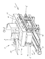
- FIG. 1 includes a not interesting here Picking system with, for example, high-speed turning machines, Article storage shelves, stacker cranes, etc. among others also an arrangement 1 of a conveyor line 2 for (shipping) container or over cartons from a container storage station a container shipping station with an intermediate Filling station 4, in the picked item 3 or bulk goods via a hopper 5 in one on the conveyor line 2 promoted, arranged under the hopper, open at the top Container 10, 11, 12 are filled, as in particular can be seen from Figure 1.
- a conveyor line 2 for (shipping) container or over cartons from a container storage station a container shipping station with an intermediate Filling station 4, in the picked item 3 or bulk goods via a hopper 5 in one on the conveyor line 2 promoted, arranged under the hopper, open at the top Container 10, 11, 12 are filled, as in particular can be seen from Figure 1.
- the article 3 or the bulk material will be over an oblique central conveyor belt 30 the hopper 5 in the arrow direction P supplied.
- the conveyor line 2 which in principle, for example, a continuous conveyor belt, a driving roller conveyor or a S Heck roller conveyor may be in the immediate area before, in and after the filling station 4 right and left, i. on both sides of the conveyor belt or the like a toothed belt or Chain drive 6 with a common dynamic drive in the form of an intermittent actuator 7, which a slip-free accelerated continuation of one or more Container concerned, located in the immediate area of Filling station 4 are located.
- each of the side toothed belts has or Chain drive 6 from each other equally spaced container-Mitêtissen 8, in the embodiment six, through which on the conveyor line 2 incoming open-topped container 10, 11, 12 isolated both in the filling position and after accelerated filling from the filling position clocked and the output side of the conveyor line 2 are fed again.
- the revolving toothed belt or chain drive 6 on both Broad sides of the conveyor line is axially symmetrical to the conveyor line designed such that associated drive plates 8 on each side in the conveying direction F of the container at the same height or length.
- the conveyor line 2 has before the toothed belt or chain drive 6 a stopper 21, which in the trajectory of subsidized container are made or the trajectory the subsidized container can release.
- the arrangement of the conveyor line 2 is made such that in particular through in the filling position, adjacent, extending transversely to the conveying direction F driver plates 8 a Gearschachtwand between hopper 5 and a container to be filled is formed.
- the six driver plates 8 are in the associated circumferential Toothed belt drive at the same distance in particular hung, wherein the distance of the container width in the conveying direction F corresponds.
- the driver plates 8 are thin-walled spring steel plates and have slots 9 on the upper side in the vertical direction.
- the driver plate 8 is shown in detail in Figures 5 and 6 shown. It has a verikales fastening tape with top bracket 26 for attachment to a Timing belt fastening point 25, in particular on the upper strand 14 the associated toothed belt drive 6, while the vertical fastening strap on the underside of the lower strand 15 in exact vertical Alignment of a Mitnhemerplatte 8 also attached or supported laterally.
- each other opposite toothed belt drives 6 with vertical axes 13 and with upper and lower chord 14, 15 on both sides of the conveyor line 2 provided, wherein the driver plates 8 approximately half are as wide as the container width transverse to the conveying direction F and both drives 6 driven by a common actuator 7, in particular clocked are.
- Each toothed belt drive 6 is a stationary vertical Container guide wall 16 is formed in the conveying direction F, which in particular between the upper and lower chords 14, 15 of the Toothed belt drive 6 is arranged, wherein the container guide wall 16, optionally together with the upper flange 14, In the area of the filling opening, a filling shaft wall in the conveying direction F trains.
- the hopper 5 can be used as a buffer funnel or with a separate Buffer funnel 17 may be formed, which has a the filling opening closing and opening horizontal slide Contains 18, wherein the two-part formed horizontal slide only with one positioned in the filling position Container 11 is opened and otherwise closed.
- the emergency facility comprises two lateral ones on each side Stopper 19, 20, through which on a continuously driven Conveyor belt through the filling station 4 running container 10, 11, 12 in the filling position and in the upstream Waiting position preferably by lateral friction can be positioned and released.
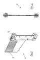
- the sensor system of the actuator 7 of the toothed belt drive 6 comprises five photoelectric sensors LS1, LS2, LS3, LS4, LS5, one inductive sensor 23 and a scanner 22 according to Figure 7, wherein on the input side of the filling station in the conveying path of Stopper 21, the separation of the containers 10, 11, 12 concerned.
- FIG. 1 it is a so-called indexer with a built-up indexer Buffer funnel provided.
- the central band promotes or the riser of the central band a product heap, at the transfer point in the boxes or in the Container is handed over.
- the function of the buffer funnel here in particular provides a two-part slider, wherein both slide halves are opened as soon as the carton is positioned below. The advantage is that you can during of the positioning process of the carton the funnel over the Sliders can already fill. Is the carton positioned the slide opens and the products fall down in the postitioned container.
- indexer here is that even if the boxes or containers are the same height, a distance held between the slider halves and the cardboard top can be, e.g. 100mm, so supernatant products not to be clamped when walking the slider halves.
- the indexer is completely empty.
- the box moves to the light barrier LS1 and drives through to the time standing at this time Mit supportiveplatte 8, right, according to Figure 7.
- the Mit supportiveplatte additionallygetaktet on the position of in FIG 7 illustrated driver plate 8, left, i. in the filling position, positively entrained the container and at the same time read.
- a second following container is now driving through the light barriers LS1 and LS2 through, until again to Driver plate 8, right, and occupies the light barrier LS3. If a third container comes, must - by the fact that the light barriers LS3 and LS4 are occupied - the light barrier LS1 activate the stopper 21, and the container remains in front of the Indexer stand.
- the light barrier LS2 is only a control light barrier.
- the indexer goes to error ("Dumping the tanks"), otherwise in a further transport of the container over the Indexer a "crash" would come about.
- the indexer clocks by one Driving position continues.
- the container reaches the Waiting position in the filling position.
- the filled container drives out, and gets on the output side conveyor line 2 discharged to a packaging station.
- the light barrier LS5 is also a control light barrier, which controls the outgoing container.
- the indexer may not switch again until this area is cleared is.
- the inductive sensor directly detects the driver plates, whereby the following function is fulfilled: that the drive via a servo motor and a corresponding Ramp, in particular an asymmetrical sine square ramp, is driven.
- the inductive sensor is aimed directly at the driver plate, but they are not really related to the beginning and the end is, i. each time a file is indexed, it is referenced once, and the servo motor steers over its entered ramp and counting clocks the position of the drive plates at.
- the indexer is out of order. Corresponding driver plates in the pass must be dismantled to clear passage to ensure. Control is everything like at Normal Bet.
- the light barrier LS3 and the light barrier LS4 are then simultaneously trigger photocell for the Stopper.
- the forwarding of the container is done by friction over the corresponding continuous conveyor belt.
- the indexer together with its inductive sensor is completely out of operation.
- the throughput is correspondingly lower, because not form-fitting and clocked through with high acceleration can.
Abstract
Description
Die Erfindung betrifft eine Anordnung einer Förderstrecke für auf der Förderstrecke geförderte, mit Artikeln oder Schüttgut in einer Füllstation über einen Fülltrichter zu befüllende, sich in der Füllstellung befindliche Behälter gemäß dem Oberbegriff des Anspruchs 1. Eine solche anordnung ist aus der DE-A-19 812 248 bekannt. Die Erfindung betrifft insbesondere denjenigen Teil einer Kommissionierautomat-Übergabestation, der die Versandbehälter der Füllstation zuführt, sie für die Dauer der Artikel- bzw. Produktübergabe unter dem Füll- oder Übergabetrichter positioniert und anschließend von der Füllstation wieder abführt.The invention relates to an arrangement of a conveyor line for conveyed on the conveyor line, with articles or Bulk material to be filled in a filling station via a hopper, in the filling position located container according to the preamble of claim 1. Such Arrangement is known from DE-A-19 812 248. The invention relates especially that part of a picking machine transfer station, which feeds the shipping containers to the filling station, for the duration of the product or product handover Positioned below the filling or transfer funnels and then discharged from the filling station again.
Nach dem Stand der Technik werden die Behälter im Bereich der Kommissionierautomatübergabe über einen stetig laufenden Fördergurt bewegt. Die Vereinzelung der ankommenden Behälter wird durch eine vor der Übergabestation angeordnete Klemmvorrichtung bewerkstelligt, welche den jeweils vordersten Behälter erfaßt und erst kurz vor Freiwerden der Füllstation weiterlaufen läßt. Direkt unter dem der ersten Klemmvorrichtung nachgeordneten Füll- bzw. Übergabetrichter befindet sich beidseits des Fördergurts eine zweite Klemmvorrichtung, die den ankommenden Behälter erfaßt und ihn bis zm Abschluß der Befüllung in der richtigen Position festhält. Anschließend wird der befüllte Behälter losgelassen, vom kontinuierlich angetriebenen Fördergurt reibschlüssig mitgenommen und aus dem Übergabebereich transportiert. Die Behälterwechselzeit und damit in vielen Fällen die Durchsatzleistung der gesamten Kommissionieranlage hängen somit von der Geschwindigkeit ab, mit der die Behälter auf dem Fördergurt reibschlüssig weitergetaktet werden. Im übrigen ist nicht sichergestellt, daß in der Füllstellung befindliche Behälter insbesondere unterschiedlicher Höhe auch einwandfrei mit Artikeln oder Schüttgut befüllt werden, ohne daß Artikel vereinzelt daneben fallen. Daneben fallende zum Teil kostspielige Artikel gehen dann normalerweise zu Bruch. In der Regel muß zumeist auch der Betrieb der Füllstation unterbrochen und die Störung behoben werden. According to the prior art, the containers are in the area the picking machine transfer over a constantly running Conveyor belt moves. The isolation of the incoming containers is by a arranged in front of the transfer station clamping device accomplished, which the respective foremost container recorded and continue to run until shortly before the filling station leaves. Just below the first clamp downstream filling or transfer funnel is located on both sides of the conveyor belt, a second clamping device, the the incoming container detected and him until the completion of the Holding the filling in the correct position. Subsequently the filled container is released, from continuously driven conveyor belt frictionally entrained and off transported to the transfer area. The container change time and thus in many cases the throughput of the whole Picking system thus depend on the speed with which the containers on the conveyor belt frictionally be further clocked. Moreover, it is not ensured that in the filling position located container in particular different Height also perfect with items or Bulk goods are filled, without the article isolated next to it fall. In addition falling partly expensive items then usually break. In general, usually also the operation of the filling station is interrupted and the fault be resolved.
Aufgabe der Erfindung ist die Schaffung einer Anordnung der eingangs genannten Art, welche mit Hilfe einfacher Mittel ein einwandfreies und effektives Befüllen eines in der Füllstellung befindlichen exakt positionierten Behälters ermöglicht und gegebenenfalls auch ein schnelleres Weitertakten der Behälter im Bereich der Füllstation erlaubt.The object of the invention is to provide an arrangement of the aforementioned type, which by means of simple means a perfect and effective filling one in the filling position located exactly positioned container allows and, if necessary, faster indexing the container is allowed in the area of the filling station.
Gelöst wird die der Erfindung zugrundeliegende Aufgabe durch eine Förderstreckenanordnung mit den im Anspruch 1 angegebenen Merkmalen.Solved the problem underlying the invention by a conveyor line arrangement with the specified in claim 1 Features.
Vorteilhaft weitergebildet wird der Erfindungsgegenstand
durch die Merkmale der Ansprüche 2 bis 14.Advantageously, the subject of the invention is further developed
by the features of
Wesen der Erfindung ist, daß in der Füllstellung befindliche, benachbarte, sich quer zur Förderrichtung erstreckende Mitnehmerplatten eine Füllschachtwand zwischen Fülltrichter und einem zu befüllenden Behälter ausbilden.Essence of the invention is that in the filling position, adjacent, extending transversely to the conveying direction driver plates a hopper wall between hopper and one to be filled Tray container.
In einer vorteilhaften Ausführungsvariante sind vorzugsweise sechs Mitnehmerplatten vorgesehen, die im umlaufenden Zahnriemen- oder Kettentrieb in einem gleichen Abstand befestigt, insbesondere eingehängt, sind, wobei der Abstand der Behälterbreite in Förderrichtung entspricht. In an advantageous embodiment variant are preferably six driver plates provided in the circulating toothed belt or chain drive attached at an equal distance, in particular, are suspended, with the distance of the Tank width in the conveying direction corresponds.
Die Mitnehmerplatten sind im besonderen dünnwandige an sich stabile Federstahlplatten, vorzugsweie mit einer Dicke von ca. 0,7mm.The driver plates are in particular thin-walled in itself stable spring steel plates, preferably with a thickness of about 0.7mm.
Die Mitnehmerplatten weisen insbesondere oberseitig Schlitze vorzugweise in Vertikalrichtung auf, welche die Elastizität erhöhen bzw. Federwirkung schaffen, wenn tatsächlich ein Hindernis in der Bewegungsbahn ist, welches dann überwunden wird.The driver plates have in particular slots on the top side preferably in the vertical direction, which the elasticity increase or create spring action when in fact an obstacle in the trajectory, which is then overcome becomes.
Besonders vorteilhaft ist es, wenn zwei gleiche, spiegelbildlich aufgebaute, einander gegenüberliegende Zahnriemen- oder Kettentriebe mit Vertikalachsen sowie mit Ober- und Untergurt beidseits der Förderstrecke vorgesehen sind, wobei die Mitnehmerplatten etwa halb so breit sind wie die Behälterbreite quer zur Förderrichtung und beide Triebe von einem gemeinsamen Antriebsmotor angetrieben, insbesondere getaktet, sind.It is particularly advantageous if two identical, mirror-image constructed, opposite toothed belt or Chain drives with vertical axes and with upper and lower belt are provided on both sides of the conveyor line, wherein the Mitnehmerplatten are about half as wide as the container width transverse to the conveying direction and both shoots from a common Drive motor driven, in particular clocked, are.
Der Zahnriemen- oder Kettentrieb kann in besonders vorteilhafter Weiterbildung der Erfindung mit einer stationären vertikalen Behälterführungswand in Förderrichtung ausgebildet sein, welche insbesondere zwischen Ober- und Untergurt des Zahnriemen- oder Kettentriebs angeordnet ist, wobei die Behälterführungswand, gegebenenfalls zusammen mit dem Obergurt, im Bereich der Füllöffung eine Füllschachtwand in Förderrichtung ausbildet.The toothed belt or chain drive can be particularly advantageous Development of the invention with a stationary vertical Container guide wall formed in the conveying direction be, which in particular between upper and lower chord of Zahnriemen- or chain drive is arranged, wherein the container guide wall, optionally together with the upper belt, In the area of the filling opening, a filling shaft wall in the conveying direction formed.
Der Fülltrichter selbst kann als Puffertrichter oder mit einem separaten Puffertrichter ausgebildet sein, welcher einen die Füllöffnung verschließenden und öffenbaren Horizontalschieber enthält, wobei der vorzugsweise zweiteilig ausgebildete Horizontalschieber nur bei einem in der Füllstellung positionierten Behälter geöffnet und ansonsten geschlossen ist. The hopper itself can be used as a buffer funnel or with a be formed separate buffer funnel, which is a the filling opening closing and opening horizontal slide contains, wherein preferably formed in two parts Horizontal slide only at one positioned in the filling position Container open and otherwise closed is.
Insbesondere ist eine Notlauf-Einrichtung zum Ein- und Austakten der zu befüllenden Behälter insbesondere bei Ausfall des Betriebs des Zahnriemen- oder Kettentriebs vorgesehen.In particular, an emergency running device for input and output the container to be filled especially in case of failure the operation of the toothed belt or chain drive provided.
Die Notlauf-Einrichtung umfaßt auf jeder Seite zwei seitliche Stopper, durch welche auf einem kontinuierlich angetriebenen Förderband durch die Füllstation laufende Behälter in der Füllstellung sowie in der vorgelagerten Wartestellung vorzugsweise durch seitlichen Reibschluß positionierbar und freigebbar sind.The emergency facility comprises two lateral ones on each side Stopper, through which on a continuously driven Conveyor belt through the filling station running container in the filling position and in the upstream waiting position preferably positionable by lateral friction and are releasable.
Die Sensorik des Stellantriebs des oder der Zahnriemen- oder Kettentriebe sowie der gegebenenfalls vorhandenen Notlauf-Einrichtung umfaßt insbesondere fünf Lichtschranken, einen Induktivgeber und einen Scanner, wobei auf der Eingangsseite der Füllstation in der Förderstrecke ein weiterer Stopper zum Vereinzeln der Behälter vorgesehen ist, welcher in die Bewegungsbahn der geförderten Behälter gestellt werden bzw. die Bewegungsbahn der geförderten Behälter freigeben kann.The sensors of the actuator of the or the toothed belt or Chain drives and possibly existing emergency running device includes in particular five light barriers, one Inductive transmitter and a scanner, being on the input side the filling station in the conveyor line another stopper is provided for separating the container, which in the Movement path of the subsidized container are provided or can release the movement path of the conveyed container.
Die Gesamtanlage kann so getroffen sein, daß eine einzige durchgehende Förderstrecke vor, in und nach der Füllstation vorzugsweise als Gurtförderer bzw. Riementrieb ausgebildet ist.The entire system can be made so that a single continuous conveyor line before, in and after the filling station preferably designed as a belt conveyor or belt drive is.
Die Förderstrecke kann im Bereich des umlaufenden Zahnriemen- oder Kettentriebs unterbrochen sein und einen separaten Gurtförderer bzw. Riementrieb mit einem eigenen Antrieb aufweisen.The conveyor line can be located in the area of the circulating toothed belt or chain drive be interrupted and a separate Have belt conveyor or belt drive with its own drive.
Die vor dem Zahnriemen- oder Kettentrieb gelegene eingangsseitige Förderstrecke kann ein Förderband, eine staudrucklose Staurollenbahn oder eine staudruckbehaftete Treibrollenbahn sein. The upstream of the toothed belt or chain drive input side Conveyor line can be a conveyor belt, a zero pressure Accumulation roller conveyor or a struckruckaktiv Treibrollenbahn be.
Der Gurtförderer bzw. Riementrieb kann im Bereich der Füllstellung auch eine stationäre obere Gleitfläche besitzen, wobei der Gurtförderer bzw. Riementrieb im Bereich der Gleitfläche über Umlenkrollen nach unten parallelversetzt ausgebildet sein kann.The belt conveyor or belt drive can in the area of the filling position also have a stationary upper sliding surface, wherein the belt conveyor or belt drive in the region of the sliding surface formed over pulleys down parallel offset can be.
Durch die Erfindung kann bei einer Füllstation ein Behälterwechsel vorzugsweise beschleunigt und insbesondere exakt durchgeführt werden. Der zu befüllende Behälter wird hierbei exakt in der Füllstellung positioniert und problemlos befüllt. Die Behälter (Kartons oder dergleichen) werden formschlüssig durch einen flächigen Mitnehmer unter einem Übergabetrichter (Puffertrichter) sehr schnell weitergetaktet. Wesen der Erfindung insbesondere ist, daß beim Herabfallen der Produkte vom Übergabetrichter in den untenstehenden Behälter, der zusätzlich unterschiedlich hoch (h bzw. h') sein kann, keine Produkte daneben fallen können. Dies wird erfindungsgeäß dadurch erreicht, daß eine schachtartige Ausbildung von der Öffnung des Übergabetrichters bis zur Öffnung des Behälters ausgebildet wird, und zwar unabhängig von der Höhe eines Behälters. Die Öffnung wird quer zur Förderrichtung durch die Mitnehmerplatten oder -schürzen selbst gebildet, die zusammen mit seitlichen Leitblechen die Gesamtöffnung bestimmen.By the invention, at a filling station, a container change preferably accelerated and in particular exactly be performed. The container to be filled is hereby positioned exactly in the filling position and filled easily. The containers (boxes or the like) become positive by a flat driver under a transfer funnel (Puffertrichter) very quickly weiteretaktet. being the invention is particularly that when falling down the Products from the transfer hopper into the containers below, the additionally different high (h or h ') be can, can not fall off any products. This is erfindungsgeäß achieved in that a shaft-like training from the opening of the transfer funnel to the opening the container is formed, regardless of the Height of a container. The opening becomes transverse to the conveying direction formed by the driver plates or aprons themselves, which together with side baffles the total opening determine.
Damit keine Produkte daneben fallen, ist das Lichtraumprofil des sogenannten Indexers auf die Behälter bzw. Kartons so abgestimmt, daß in etwa vorne und hinten gesehen in Förderrichtung nur ein Gesamtspiel von ca.6 mm Gesamtspiel besteht. Der Behälter oder Karton hat also in Förderrichtung lediglich ein Gesamtspiel von ca. 6mm. Dadurch, daß die üblichen Produkte ungefähr 12mm bis 15mm Mindestgröße aufweisen, kann kein Produkt beim Einfüllen daneben fallen.So that no products fall by the way, the gauge is of the so-called indexer on the containers or boxes, that seen in about the front and rear in the conveying direction only a total game of approx. 6 mm total game exists. The container or carton thus has only in the conveying direction a total game of about 6mm. In that the usual Products may have approximately 12mm to 15mm minimum size no product will fall off during filling.
Im besonderen weist der Indexer einen Zahnriemen- oder Kettentrieb links und rechts seitlich des Behälters mit vertikalen Achsen auf. Dieser Antrieb wird durch eine gemeinsame Kette oder einen gemeinsamen doppelt verzahnten Zahnriemen von einem einzigen Servomotor bzw. Stellantrieb angetrieben. Am jedem Zahnriemen- oder Kettentrieb sind insbesondere sechs Mitnehmerplatten vorzugsweise aus Federstahl montiert, die in etwa die halbe Behälterbreite darstellen. Dadurch, daß der linke und der rechte Zahnriemen- oder Kettentrieb über einen Antrieb synchronisiert sind, ist es möglich, daß die Mitnehmerplatten den Behälter unter die Übergabestelle weitertakten. In diesem Moment bilden die Mitnehmerplatten oder -schürzen in Kombination mit der Übergabestelle und dem Behälter einen Schacht, der so eng gestaltet ist, daß auch die kleinsten Produkte nicht danebenfallen können.In particular, the indexer has a toothed belt or chain drive left and right side of the container with vertical Axes up. This drive is by a common Chain or a common double toothed timing belt driven by a single servomotor or actuator. On each toothed belt or chain drive are in particular six drive plates preferably made of spring steel, which represent about half the container width. Thereby, that the left and the right toothed belt or chain drive are synchronized via a drive, it is possible that the driver plates the container under the transfer point further overclock. At this moment, the driver plates form or aprons in combination with the transfer point and the Container a shaft that is designed so tight that too the smallest products can not fail.
Weiterhin ist auch an eine Notlaufeigenschaft gedacht. Sollten die seitlichen Antriebe bzw. die Mitnehmerplatten nicht mehr funktionsfähig sein, ist es möglich, durch Demontage der im Durchlauf befindlichen Mitnehmerplatten (vorzugsweise hier insgesamt vier - bei sechs gleich beabstandenten Mitnehmerplatten auf jeder Seite) und durch sensorische Betätigung von zwei Stoppern, die jeweils den Behälter in der Übergabe- bzw. in der Wartepostion fixieren, zumindest im Notbetrieb weiterfahren zu können.Furthermore, it is also intended for an emergency running property. Should the lateral drives or the driver plates not be more functional, it is possible by dismantling the pass plates located in the passage (preferably here a total of four - with six equally spaced driver plates on each side) and by sensory activity of two stoppers each holding the container in the transfer or fix in the waiting position, at least in emergency mode to be able to continue.
Die Sensorik besteht aus fünf Lichtschranken, einem Induktivgeber und einem Scanner. Ferner existiert ein Stopper, um die Behälter vereinzelt einfahren lassen zu können. Darüber hinaus gibt es zwei weitere Stopper, die bei einem eventuellen Notbetrieb, bei welchem die Mitnehmerplatten zum Teil abmontiert und nicht mehr in Funktion sind, die Position der Behälter bestimmen.The sensor system consists of five photoelectric sensors, an inductive sensor and a scanner. Furthermore, there is a stopper to to let the containers retract occasionally. About that There are also two more stoppers that will be included in any event Emergency operation, in which the driver plates partially removed and are no longer in function, the position of Determine container.
Durch die Erfindung wird mit Bezug auf den eingangs diskutierten Stand der Technik die reibschlüssige Mitnahme der Behälter durch eine formschlüssige Mitnahme ersetzt, und zwar durch die erfindungsgemäß vorgesehenen Mitnehmerplatten, die in einen Eingriff mit in die Füllstation einzutaktenden Behältern der Förderstrecke gelangen können.The invention will be described with reference to the initially discussed Prior art, the frictional entrainment of the container replaced by a positive entrainment, namely by the inventively provided driver plates, the in engagement with einzutaktenden in the filling container can reach the conveyor line.
Die Mitnehmerplatten hintergreifen auf der Eingangsseite der Füllstation die Behälter und ermöglichen gegebenenfalls aus dem Stillstand heraus eine große Beschleunigung der Behälter, und zwar unter Eingriff einer Mitnehmerplatte auf der Behälterrückseite, welche der Förderrichtung abgewandt ist. Da die Positionierung der Behälter formschlüssig, und nicht durch Klemmung der Behälter wie nach dem Stand der Technik erfolgt, können nicht nur vergleichweise stabile Behälter wie zum Beispiel aus Kunststoff, sondern auch Behälter aus empfindlicherem Material, wie zum Beispiel aus Pappkarton, erfindungsgemäß verwendet werden.The driver plates engage behind on the input side of the Fill the containers and allow if necessary standstill a great acceleration of the containers, under the engagement of a driver plate on the Container rear side, which faces away from the conveying direction. Because the positioning of the container is form-fitting, and not by clamping the container as in the prior art not only can comparatively stable containers such as plastic, but also made of containers more sensitive material, such as cardboard, used according to the invention.
Die Erfindung wird nachfolgend anhand eines Ausführungsbeispiels unter Bezugnahme auf die beigefügte Zeichnung näher beschrieben; es zeigen:
- Fig. 1
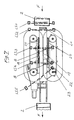
- in einer schematischen perspektivischen Ansicht eine Anordnung einer Förderstrecke einer Kommissionieranlage im Bereich einer Füllstation, in welcher offene auf der Förderstrecke geförderte Behälter mit Artikeln bzw. Produkten befüllt werden und anschließend einer Versandstation zugeführt werden können, wobei seitlich vom Durchlauf der Behälter bzw. seitlich von der Förderstrecke jeweils ein doppelter Zahnriementrieb mit Vertikalachsen mit Mitnehmerplatten vorgesehen ist, die von einem gemeinsamen Stellantrieb über einen Zahnriemen angetrieben sind,
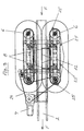
- Fig. 2
- die Anordnung nach Figur 1 in einer schematischen perspektivischen Ansicht, wobei der Fülltrichter und der Puffertrichter weggelassen sind,
- Fig. 3
- eine schematische Draufsicht auf die Anordnung nach
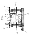
Figur 2 unter Weglassung der Behälter, - Fig. 4
- eine schematische Stirnansicht auf die Anordnung
nach
Figur 2, wobei auf der linken Seite die Mitnehmerplatte des linken doppelten Zahnriementriebs weggelassen ist, - Fig. 5
- eine Mitnehmerplatte in einer perspektivischen Ansicht von schräg oben,
- Fig. 6
- die Mitnehmereplatte nach Figur 5 in einer Stirnansicht, und
- Fig. 7
- die Anordnung nach den Figuren 1
bis 4 mit eingangs- und ausgangsseitigem Anschluß einer Förderstrecke sowie mit Darstellung von Lichtschranken.
- Fig. 1
- in a schematic perspective view of an arrangement of a conveyor line of a picking in the region of a filling station, in which open on the conveyor line funded container filled with articles or products and can then be fed to a shipping station, wherein the side of the passage of the container or laterally of the Conveyor each a double toothed belt drive is provided with vertical axes with driver plates, which are driven by a common actuator via a toothed belt,
- Fig. 2
- the arrangement of Figure 1 in a schematic perspective view, wherein the hopper and the buffer funnel are omitted,
- Fig. 3
- a schematic plan view of the arrangement of Figure 2 with the omission of the container,
- Fig. 4
- 2 is a schematic end view of the arrangement according to FIG. 2, the left double-toothed belt drive plate being left out on the left-hand side,
- Fig. 5
- a driver plate in a perspective view obliquely from above,
- Fig. 6
- the Mitnehmereplatte according to Figure 5 in an end view, and
- Fig. 7
- the arrangement of Figures 1 to 4 with input and output side connection of a conveyor line and with representation of light barriers.
Gemäß Zeichnung umfaßt eine hier nicht näher interessierende
Kommissionieranlage mit zum Beispiel Schnelldrehautomaten,
Artikellagerregalen, Regalbediengeräten, etc. unter anderem
auch eine Anordnung 1 einer Förderstrecke 2 für (Versand-)Behälter
bzw. Überkartons von einer Behältervorratsstation zu
einer Behälterversandstation mit einer zwischengeordneten
Füllstation 4, in der kommissionierte Artikel 3 oder Schüttgut
über einen Fülltrichter 5 in einen auf der Förderstrecke
2 geförderten, unter dem Fülltrichter angeordneten, oben offenen
Behälter 10, 11, 12 abgefüllt werden, wie dies insbesonderer
der Figur 1 zu entnehmen ist.According to the drawing includes a not interesting here
Picking system with, for example, high-speed turning machines,
Article storage shelves, stacker cranes, etc. among others
also an arrangement 1 of a
Die Artikel 3 oder das Schüttgut werden über ein schräges
zentrales Förderband 30 dem Fülltrichter 5 in Pfeilrichtung
P zugeführt.The
Die Förderstrecke 2, welche grundsätzlich beispielsweise ein
durchgehendes Förderband, eine Treibrollenbahn oder eine
Staurollenbahn sein kann, besitzt im unmittelbaren Bereich
vor, in und nach der Füllstation 4 rechts und links, d.h.
beidseits des Förderbands oder dergleichen einen Zahnriemenoder
Kettentrieb 6 mit einem gemeinsamen dynamischen Antrieb
in Form eines intermittierenden Stellantriebs 7, welcher einen
schlupffreien beschleunigten Weitertakt eines oder mehrerer
Behälter besorgt, die sich im unmittelbaren Bereich der
Füllstation 4 befinden.The
Insbesondere besitzt jeder der seitlichen Zahnriemen- oder
Kettentriebe 6 voneinander gleich beabstandete Behälter-Mitnehmerplatten
8, im Ausführungsbeispiel sechs, durch welche
auf der Förderstrecke 2 ankommende oben offene Behälter 10,
11, 12 vereinzelt sowohl in die Füllstellung als auch nach
einem Befüllen aus der Füllstellung beschleunigt getaktet
und ausgangsseitig der Förderstrecke 2 wieder zugeführt werden.In particular, each of the side toothed belts has or
Der umlaufende Zahnriemen- oder Kettentrieb 6 auf beiden
Breitseiten der Förderstrecke ist axialsymmetrisch zur Förderstrecke
dergestalt aufgebaut, daß zugeordnete Mitnehmerplatten
8 auf jeder Seite in Förderrichtung F der Behälter
auf gleicher Höhe bzw. Länge liegen.The revolving toothed belt or
Die Förderstrecke 2 besitzt vor dem Zahnriemen- oder Kettentrieb
6 einen Stopper 21, welcher in die Bewegungsbahn der
geförderten Behälter gestellt werden bzw. die Bewegungsbahn
der geförderten Behälter freigeben kann.The
Die Anordnung der Förderstrecke 2 ist so getroffen, daß insbesondere
durch in der Füllstellung befindliche, benachbarte,
sich quer zur Förderrichtung F erstreckende Mitnehmerplatten
8 eine Füllschachtwand zwischen Fülltrichter 5 und
einem zu befüllenden Behälter ausgebildet wird.The arrangement of the
Die sechs Mitnehmerplatten 8 sind im zugehörigen umlaufenden
Zahnriementrieb in einem gleichen Abstand insbesondere eingehängt,
wobei der Abstand der Behälterbreite in Förderrichtung
F entspricht.The six
Die Mitnehmerplatten 8 sind dünnwandige Federstahlplatten
und weisen oberseitig Schlitze 9 in Vertikalrichtung auf.
Die Mitnehmerplatte 8 ist im einzelnen in den Figuren 5 und
6 dargestellt. Sie besitzt ein verikales Befestigungsband
mit oberseitiger Halterung 26 für eine Befestigung an einer
Zahnriemenbefestigungstelle 25, insbesondere am Obertrum 14
des zugehörigen Zahnriementriebs 6, während das vertikale Befestigungsband
unterseitig am Untertrum 15 in exakter vertikaler
Ausrichtung einer Mitnhemerplatte 8 ebenfalls befestigt
oder seitlich abgestützt ist.The
Es sind also zwei gleiche, spiegelbildlich aufgebaute, einander
gegenüberliegende Zahnriementriebe 6 mit Vertikalachsen
13 sowie mit Ober- und Untergurt 14, 15 beidseits der Förderstrecke
2 vorgesehen, wobei die Mitnehmerplatten 8 etwa halb
so breit sind wie die Behälterbreite quer zur Förderrichtung
F und beide Triebe 6 von einem gemeinsamen Stellantrieb 7 angetrieben,
insbesondere getaktet, sind.So there are two identical, mirror-image built, each other
opposite toothed belt drives 6 with
Jeder Zahnriementrieb 6 ist mit einer stationären vertikalen
Behälterführungswand 16 in Förderrichtung F ausgebildet, welche
insbesondere zwischen Ober- und Untergurt 14, 15 des
Zahnriementriebs 6 angeordnet ist, wobei die Behälterführungswand
16, gegebenenfalls zusammen mit dem Obergurt 14,
im Bereich der Füllöffung eine Füllschachtwand in Förderrichtung
F ausbildet. Each
Der Fülltrichter 5 kann als Puffertrichter oder mit einem separaten
Puffertrichter 17 ausgebildet sein, welcher einen
die Füllöffnung verschließenden und öffenbaren Horizontalschieber
18 enthält, wobei der zweiteilig ausgebildete Horizontalschieber
nur bei einem in der Füllstellung positionierten
Behälter 11 geöffnet und ansonsten geschlossen ist.The hopper 5 can be used as a buffer funnel or with a
Es ist ferner eine Notlauf-Einrichtung zum Ein- und Austakten
der zu befüllenden Behälter 10, 11, 12 bei Ausfall des
Betriebs des Zahnriementriebs 6 vorgesehen.It is also an emergency running device for input and output
the container to be filled 10, 11, 12 in case of failure of
Operation of the
Die Notlauf-Einrichtung umfaßt auf jeder Seite zwei seitliche
Stopper 19, 20, durch welche auf einem kontinuierlich angetriebenen
Förderband durch die Füllstation 4 laufende Behälter
10, 11, 12 in der Füllstellung sowie in der vorgelagerten
Wartestellung vorzugsweise durch seitlichen Reibschluß
positionierbar und freigebbar sind.The emergency facility comprises two lateral ones on each
Die Sensorik des Stellantriebs 7 der Zahnriementriebe 6 umfaßt
fünf Lichtschranken LS1, LS2, LS3, LS4, LS5, einen Induktivgeber
23 und einen Scanner 22 gemäß Figur 7, wobei auf
der Eingangsseite der Füllstation in der Förderstrecke der
Stopper 21 das Vereinzeln der Behälter 10, 11, 12 besorgt.The sensor system of the
Es ist also gemäß Figur 1 ein sogenannter Indexer mit aufgebautem Puffertrichter vorgesehen. Von links fördert das Zentralband oder das Steigband des Zentralbandes einen Produkthaufen, der an der Übergabestelle in die Kartons bzw. in die Behälter übergeben wird. Die Funktion des Puffertrichters hier im speziellen sieht einen zweiteiligen Schieber vor, wobei beide Schieberhälften geöffnet werden, sobald der Karton unterhalb positionert ist. Der Vorteil ist, daß man während des Positioniervorganges des Kartons den Trichter über den Schiebern schon füllen kann. Ist der Karton positioniert, geht der Schieber auf, und die Produkte fallen nach unten in den postitionierten Behälter.Thus, according to FIG. 1, it is a so-called indexer with a built-up indexer Buffer funnel provided. From the left, the central band promotes or the riser of the central band a product heap, at the transfer point in the boxes or in the Container is handed over. The function of the buffer funnel here in particular provides a two-part slider, wherein both slide halves are opened as soon as the carton is positioned below. The advantage is that you can during of the positioning process of the carton the funnel over the Sliders can already fill. Is the carton positioned the slide opens and the products fall down in the postitioned container.
Ein weiterer Vorteil des Indexers hier ist, daß auch, wenn die Kartons oder die Behälter gleich hoch sind, ein Abstand zwischen den Schieberhälften und der Kartonoberkante gehalten werden kann, z.B. 100mm, damit überstehende Produkte beim Zugehen der Schieberhälften nicht geklemmt werden.Another advantage of the indexer here is that even if the boxes or containers are the same height, a distance held between the slider halves and the cardboard top can be, e.g. 100mm, so supernatant products not to be clamped when walking the slider halves.
Der Ablauf bzw. die Funktionsweise des Indexers ist wie folgt.The procedure or functioning of the indexer is like follows.
Der Indexer ist vollkommen leer. Der Karton fährt zur Lichtschranke
LS1 und fährt durch bis zur zu dieser Zeit stehenden
Mitnehmerplatte 8, rechts, gemäß Figur 7. Dann wird die
Mitnehmerplatte durchgetaktet auf die Position der in Figur
7 dargestellten Mitnehmerplatte 8, links, d.h. in die Befüllposition,
formschlüssig der Behälter mitgenommen und gleichzeitig
gelesen. Ein zweiter folgender Behälter fährt jetzt
durch die Lichtschranken LS1 und LS2 durch, bis wieder zur
Mitnehmerplatte 8, rechts, und belegt die Lichtschranke LS3.
Kommt eine dritter Behälter, muß - dadurch, daß die Lichtschranken
LS3 und LS4 besetzt sind - die Lichtschranke LS1
den Stopper 21 aktivieren, und der Behälter bleibt vor dem
Indexer stehen. Die Lichtschranke LS2 ist nur eine Kontroll-Lichtschranke.
Sollte aus irgendeinem Grund der Stopper
überfahren werden und die Lichtschranke LS2 belegt sein,
geht der Indexer auf Störung ("Vereinzeln der Behälter"), andernfalls
bei einem Weitertransport des Behälters über den
Indexer ein "Crash" zustande käme. Nach dem Befüllvorgang
des Behälters in der Befüllstellung taktet der Indexer um eine
Mitnehmerposition weiter. Damit gelangt der Behälter der
Wartestellung in die Befüllposition. Der befüllte Behälter
fährt hinaus, und wird auf der ausgangsseitigen Förderstrecke
2 bis zu einer Verpackungsstation abgeführt. The indexer is completely empty. The box moves to the light barrier
LS1 and drives through to the time standing at this
Die Lichtschranke LS5 ist auch eine Kontroll-Lichschranke, die den ausgefahrenden Behälter kontrolliert. Der Indexer darf erst wieder weiterschalten, wenn dieser Bereich freigefahren ist. Der Induktivgeber dedektiert direkt die Mitnehmerplatten, wobei folgende Funktion erfüllt ist: Dadurch, daß der Antrieb über einen Servomotor und eine entsprechenden Rampe, insbesondere eine asymetrische Sinusquadratrampe, angetrieben wird.The light barrier LS5 is also a control light barrier, which controls the outgoing container. The indexer may not switch again until this area is cleared is. The inductive sensor directly detects the driver plates, whereby the following function is fulfilled: that the drive via a servo motor and a corresponding Ramp, in particular an asymmetrical sine square ramp, is driven.
Der Induktivgeber ist direkt auf die Mitnehmerplatte gerichtet, die aber jetzt nicht wirklich auf Anfang und Ende bezogen ist, d.h. bei jedem Weitertakten wird einmal referenziert, und der Servomoter steuert über seine eingegebene Rampe und mitzählende Takte die Position der Mitnehmerplatten an.The inductive sensor is aimed directly at the driver plate, but they are not really related to the beginning and the end is, i. each time a file is indexed, it is referenced once, and the servo motor steers over its entered ramp and counting clocks the position of the drive plates at.
Der Indexer ist außer Funktion. Entsprechende Mitnehmerplatten im Durchlauf müssen demontiert sein, um freie Durchfahrt zu gewährleisten. Steuerungsmäßig spielt sich alles wie bei Normalbetireb ab. Die Lichtschranke LS3 und die Lichtschranke LS4 sind dann gleichzeitig Triggerlichtschranke für die Stopper. Das Weiterleiten der Behälter geschieht reibschlüssig über das entsprechende durchlaufende Förderband. Der Indexer samt seinem Induktivgeber ist komplett außer Betrieb. Der Durchsatz ist entsprechend geringer, weil nicht formschlüssig und mit starker Beschleunigung durchgetaktet werden kann.The indexer is out of order. Corresponding driver plates in the pass must be dismantled to clear passage to ensure. Control is everything like at Normal Bet. The light barrier LS3 and the light barrier LS4 are then simultaneously trigger photocell for the Stopper. The forwarding of the container is done by friction over the corresponding continuous conveyor belt. The indexer together with its inductive sensor is completely out of operation. The throughput is correspondingly lower, because not form-fitting and clocked through with high acceleration can.
Claims (14)
- An assembly (1) comprising conveyor means (2) for containers (10, 11, 12) transported on said conveyor means (2) to be filled with articles (3) or bulk material in a filling station (4) via a filling hopper (5) and located in the filling position, in which said conveyor means (2) exhibit, directly upstream of, in, and/or directly downstream of, said filling station (4), on at least one side thereof, a continuously circulating synchronous belt or chain drive (6) with its own intermittent actuator (7) and container-entraining plates (6) set at a distance from each other, which can be brought into form-fitting engagement with open-top containers (10, 11, 12) arriving on the conveyor means (2) and by means of which the containers can be individually clocked, preferably with acceleration, into the filling position and away from the filling position after filling has been carried out and can optionally be returned to said conveyor means (2) by an external route,
characterized in that
adjacent entrainer plates (8) located in the filling position and extending at right angles to the direction of transport (F) form a feeder chute wall between said filling hopper (5) and a container to be filled. - An assembly as defined in claim 1,
characterized in that
preferably six entrainer plates (8) are provided and are fixed, in particular suspended, in the continuously circulating synchronous belt or chain drive at equal distances, said distance being equal to the width of the container in the direction of transport (F). - An assembly as defined in claim 1 or claim 2,
characterized in that
the entrainer plates (8) are thin-walled spring steel plates. - An assembly as defined in any one of claims 1 to 3,
characterized in that
the entrainer plates (66) have at their upper end slits (33) preferably extending vertically. - An assembly as defined in any one of claims 1 to 4,
characterized in that
two identical synchronous belt or chain drives (6) are provided on each side of the conveyor means (2) in mirror-inverted relationship to each other, said drives having vertical axles (13) and upper and lower belts (14, 15), and the entrainer plates (8) are approximately half as wide as the width of the container at right angles to the direction of transport (F) and both drives (6) are driven, in particular clocked, by a common actuator (7). - An assembly as defined in any one of claims 1 to 5,
characterized in that
the synchronous belt or chain drive (6) exhibits a stationary vertical container guide wall (16) in the direction of transport (F), which is disposed, in particular, between said upper and lower belts (14, 15) of the synchronous belt or chain drive (6), which container guide wall (16) forms, in the region of the filling hole and optionally together with the upper belt (14), a feeder chute wall extending in the direction of transport (F). - An assembly as defined in any one of claims 1 to 6,
characterized in that
the filling hopper (5) is in the form of a control funnel or is provided with a separate control funnel (17), which contains a horizontal slide (18) designed to open or close the filling hole, and the horizontal slide, which is preferably composed of two parts, is normally in the closed position and is only opened when the container (11) is in the filling position. - An assembly as defined in any one of claims 1 to 7,
characterized in that
there is provided an emergency device for clocking-in or clocking-out the containers (10, 11, 12) before and after filling thereof respectively, particularly in the case of a break-down of the synchronous belt or chain drive (6). - An assembly as defined in claim 8,
characterized in that
the emergency device comprises two lateral chain stoppers (19, 20) on each side, by means of which containers (10, 11, 12) travelling on a continuously driven conveyor belt through the filling station (4) can be held in, preferably by lateral frictional engagement, or released from, the filling position or the upstream queued position. - An assembly as defined in any one of claims 1 to 9,
characterized in that
the sensor means for the actuator (7) of the synchronous belt or chain drive(s) (6) and any emergency device present comprise five photoelectric barriers (LS1, LS2, LS3, LS4, LS5), an inductive transmitter (23) and a scanner (22), whilst on the input side of the filling station in the conveyor means there is provided another stopper (21) for the purpose of isolating the containers (10, 11, 12) from the queue, which stopper can be projected into the path of movement of the transported container or moved out therefrom so as to unblock the path of movement of the transported container. - An assembly as defined in any one of claims 1 to 10,
characterized in that
a single continuous conveyor (2) is provided upstream of, in, and downstream of, the filling station (4) preferably in the form of a belt conveyor or belt drive. - An assembly as defined in claim 11,
characterized in that
the conveyor means (2) are interrupted in the region of the continuously running synchronous belt or chain drive (6) and exhibit a separate belt conveyor or belt drive having its own drive. - An assembly as defined in claim 12,
characterized in that
the conveyor means (2) located on the entrance side upstream of the synchronous belt or chain drive (6) comprise a conveyor belt, a pile-up roller conveyor void of back pressure or a driven roller conveyor counteracting back pressure. - An assembly as defined in claim 12 or claim 13,
characterized in that
the belt conveyor or belt drive possesses a stationary upper slip plane in the region of the filling position, and, in the region of the slip plane, the belt conveyor or belt drive can be staggered downwardly in parallel via deflection rollers.
Applications Claiming Priority (3)
| Application Number | Priority Date | Filing Date | Title |
|---|---|---|---|
| DE19949440A DE19949440A1 (en) | 1999-10-14 | 1999-10-14 | Conveyor track arrangement in a filling station |
| DE19949440 | 1999-10-14 | ||
| PCT/EP2000/009794 WO2001026972A1 (en) | 1999-10-14 | 2000-10-06 | Conveyor section arrangement in a filling station |
Publications (2)
| Publication Number | Publication Date |
|---|---|
| EP1220786A1 EP1220786A1 (en) | 2002-07-10 |
| EP1220786B1 true EP1220786B1 (en) | 2003-08-06 |
Family
ID=7925548
Family Applications (1)
| Application Number | Title | Priority Date | Filing Date |
|---|---|---|---|
| EP00975856A Expired - Lifetime EP1220786B1 (en) | 1999-10-14 | 2000-10-06 | Conveyor section arrangement in a filling station |
Country Status (6)
| Country | Link |
|---|---|
| US (1) | US6622851B1 (en) |
| EP (1) | EP1220786B1 (en) |
| AT (1) | ATE246633T1 (en) |
| DE (3) | DE19949440A1 (en) |
| ES (1) | ES2203531T3 (en) |
| WO (1) | WO2001026972A1 (en) |
Families Citing this family (12)
| Publication number | Priority date | Publication date | Assignee | Title |
|---|---|---|---|---|
| DE19949440A1 (en) * | 1999-10-14 | 2001-05-03 | Knapp Logistik Automation | Conveyor track arrangement in a filling station |
| US7175516B2 (en) * | 2002-01-18 | 2007-02-13 | Memco | Poultry processing hub and belt assembly |
| US6915894B2 (en) * | 2003-06-30 | 2005-07-12 | Emhart Glass S.A. | Container inspection machine |
| US6793067B1 (en) * | 2003-06-30 | 2004-09-21 | Emhart Glass S.A. | Container inspection machine |
| DE10356073B4 (en) * | 2003-12-01 | 2007-02-15 | Sig Technology Ltd. | Method and device for filling open-top beverage containers |
| CN100460160C (en) * | 2006-04-03 | 2009-02-11 | 四川大学 | Synchronous automatic fetching device with drive in type of self-adapting elimination of errors |
| DE102008023541A1 (en) * | 2008-05-14 | 2009-12-03 | Kannenberg, Hartmut | Device for transport for filling of lined up containers, cartons or bags, has upper roller track and motor driven horizontally rotating belt under roller track |
| DE102009027280A1 (en) * | 2009-06-29 | 2011-03-03 | Robert Bosch Gmbh | Device for transporting containers |
| US20120240525A1 (en) * | 2011-03-25 | 2012-09-27 | Summerford Wayne C | Method and System for Applying Tamper Evident Banding |
| DE102014224404A1 (en) * | 2014-11-28 | 2016-06-02 | Leicht Stanzautomation Gmbh | Filling and changing device for filling containers with bulk material |
| CN107570987A (en) * | 2017-09-22 | 2018-01-12 | 昆山佰奥智能装备股份有限公司 | The linear reflux cycle line of intelligence |
| CN117361019B (en) * | 2023-12-08 | 2024-02-06 | 招远市河西金矿有限公司 | Chute for mineral aggregate conveying |
Family Cites Families (14)
| Publication number | Priority date | Publication date | Assignee | Title |
|---|---|---|---|---|
| DE1120978B (en) * | 1960-05-23 | 1961-12-28 | Helmut Engelbert Olesch | Shroud conveyor with profile strip side walls |
| US3967434A (en) * | 1975-05-19 | 1976-07-06 | Portion Packaging Limited | Cartonning apparatus |
| WO1983004401A1 (en) * | 1982-06-07 | 1983-12-22 | Pennwalt Corporation | Box filling apparatus |
| DE4018517A1 (en) * | 1990-06-09 | 1991-12-12 | Manfred Hauers | PACKING DEVICE |
| DE4022162A1 (en) * | 1990-07-12 | 1992-01-16 | Licentia Gmbh | DEVICE AND METHOD FOR STACKING SMALL GOODS |
| IT1256765B (en) * | 1992-01-17 | 1995-12-15 | Cavanna Spa | DEVICE FOR CONVEYING PRODUCTS INSERTED IN PACKAGES WITH FLAPS AND RELATED PROCEDURE. |
| JP3225410B2 (en) * | 1992-06-09 | 2001-11-05 | 四国化工機株式会社 | Chain conveyor take-up |
| US5833046A (en) * | 1996-09-24 | 1998-11-10 | Riverwood International Corporation | Partition control assembly |
| US5897291A (en) * | 1997-10-07 | 1999-04-27 | The Procter & Gamble Company | Apparatus and method for forming arrays of articles for packaging |
| US6059094A (en) * | 1997-11-21 | 2000-05-09 | R.R. Howell Company | Slide gate for an en-masse conveyor system |
| DE19812248A1 (en) * | 1998-01-16 | 1999-07-22 | Rovema Gmbh | Bag insertion into folding boxes on conveyor |
| US6128886A (en) * | 1999-04-09 | 2000-10-10 | Wayne Automation Corporation | High speed inner packing inserter |
| DE19949440A1 (en) * | 1999-10-14 | 2001-05-03 | Knapp Logistik Automation | Conveyor track arrangement in a filling station |
| US6231299B1 (en) * | 1999-11-05 | 2001-05-15 | John Robert Newsome | Apparatus for aligning stacked documents moving along a conveyor |
-
1999
- 1999-10-14 DE DE19949440A patent/DE19949440A1/en not_active Withdrawn
- 1999-11-27 DE DE29920912U patent/DE29920912U1/en not_active Expired - Lifetime
-
2000
- 2000-10-06 AT AT00975856T patent/ATE246633T1/en active
- 2000-10-06 EP EP00975856A patent/EP1220786B1/en not_active Expired - Lifetime
- 2000-10-06 ES ES00975856T patent/ES2203531T3/en not_active Expired - Lifetime
- 2000-10-06 DE DE50003217T patent/DE50003217D1/en not_active Expired - Lifetime
- 2000-10-06 WO PCT/EP2000/009794 patent/WO2001026972A1/en active IP Right Grant
- 2000-10-06 US US10/110,844 patent/US6622851B1/en not_active Expired - Lifetime
Also Published As
| Publication number | Publication date |
|---|---|
| DE19949440A1 (en) | 2001-05-03 |
| ES2203531T3 (en) | 2004-04-16 |
| ATE246633T1 (en) | 2003-08-15 |
| WO2001026972A1 (en) | 2001-04-19 |
| US6622851B1 (en) | 2003-09-23 |
| EP1220786A1 (en) | 2002-07-10 |
| DE29920912U1 (en) | 2000-05-11 |
| DE50003217D1 (en) | 2003-09-11 |
Similar Documents
| Publication | Publication Date | Title |
|---|---|---|
| EP0959002B1 (en) | Device for packaging groups of (single-)packages | |
| AT391671B (en) | METHOD AND DEVICE FOR AUTOMATIC STACKING, STORAGE AND REMOVAL OF ITEMS | |
| EP1073598B1 (en) | Device for processing bottles | |
| EP1220786B1 (en) | Conveyor section arrangement in a filling station | |
| EP2032484B1 (en) | Air conveyor for bottles | |
| WO2020094289A2 (en) | Device for grouping containers | |
| DE102019126522A1 (en) | METHOD FOR PACKAGING ARTICLES AND RELATED PACKING MACHINE | |
| DE4441700A1 (en) | Device for transporting bottles which are at risk of tipping and which have a collar arranged underneath the closure | |
| EP2976277A1 (en) | Method and device for transporting packaging containers | |
| DE4432026A1 (en) | Device for merging several product lines | |
| DE3916424C2 (en) | ||
| EP0909706B1 (en) | Method and apparatus for handling flexible pouches | |
| EP3450355A1 (en) | Conveying plant | |
| EP0852559B1 (en) | Device and process for arranging glass containers to fit on pallets | |
| DE2926792A1 (en) | RECEIVING STATION OF A PNEUMATIC CONVEYOR FOR THE TRANSPORT OF ROD-SHAPED ITEMS FROM THE TOBACCO-PROCESSING INDUSTRY, IN PARTICULAR OF FILTER RODS | |
| EP1238910B1 (en) | Apparatus for packaging elongate objects | |
| DE102013207138B4 (en) | Method and device for conveying and handling bundles with at least two strapped articles | |
| DE19751967B4 (en) | Device, in particular for lane division or for transport, of cargo, z. As bottles, beverage cans and the like | |
| EP1089926B1 (en) | Conveyor section arrangement for containers being filled with items or bulk material at a filling station | |
| EP0319642B1 (en) | Method for transporting wire brackets for bottles of sparkling wine from a loading to a further work station | |
| EP3896014B1 (en) | Transport device for items and method for transporting items | |
| EP1422140B1 (en) | Device and method for filling a continuous cartonmachine | |
| DE4231993C2 (en) | Method and device for converting a multi-lane flow into a single-lane flow | |
| EP0936146A1 (en) | Packaging line for the automatic packaging of coins | |
| DE4325009A1 (en) | Process and apparatus for transporting packs or the like |
Legal Events
| Date | Code | Title | Description |
|---|---|---|---|
| PUAI | Public reference made under article 153(3) epc to a published international application that has entered the european phase |
Free format text: ORIGINAL CODE: 0009012 |
|
| 17P | Request for examination filed |
Effective date: 20020401 |
|
| AK | Designated contracting states |
Kind code of ref document: A1 Designated state(s): AT BE CH CY DE DK ES FI FR GB GR IE IT LI LU MC NL PT SE |
|
| GRAH | Despatch of communication of intention to grant a patent |
Free format text: ORIGINAL CODE: EPIDOS IGRA |
|
| GRAH | Despatch of communication of intention to grant a patent |
Free format text: ORIGINAL CODE: EPIDOS IGRA |
|
| GRAA | (expected) grant |
Free format text: ORIGINAL CODE: 0009210 |
|
| AK | Designated contracting states |
Designated state(s): AT DE ES FR GB IT |
|
| REG | Reference to a national code |
Ref country code: GB Ref legal event code: FG4D Free format text: NOT ENGLISH |
|
| REG | Reference to a national code |
Ref country code: IE Ref legal event code: FG4D Free format text: GERMAN |
|
| REF | Corresponds to: |
Ref document number: 50003217 Country of ref document: DE Date of ref document: 20030911 Kind code of ref document: P |
|
| GBT | Gb: translation of ep patent filed (gb section 77(6)(a)/1977) |
Effective date: 20031111 |
|
| REG | Reference to a national code |
Ref country code: IE Ref legal event code: FD4D |
|
| REG | Reference to a national code |
Ref country code: ES Ref legal event code: FG2A Ref document number: 2203531 Country of ref document: ES Kind code of ref document: T3 |
|
| ET | Fr: translation filed | ||
| PLBE | No opposition filed within time limit |
Free format text: ORIGINAL CODE: 0009261 |
|
| STAA | Information on the status of an ep patent application or granted ep patent |
Free format text: STATUS: NO OPPOSITION FILED WITHIN TIME LIMIT |
|
| 26N | No opposition filed |
Effective date: 20040507 |
|
| REG | Reference to a national code |
Ref country code: FR Ref legal event code: PLFP Year of fee payment: 16 |
|
| REG | Reference to a national code |
Ref country code: FR Ref legal event code: PLFP Year of fee payment: 17 |
|
| REG | Reference to a national code |
Ref country code: FR Ref legal event code: PLFP Year of fee payment: 18 |
|
| REG | Reference to a national code |
Ref country code: DE Ref legal event code: R082 Ref document number: 50003217 Country of ref document: DE |
|
| REG | Reference to a national code |
Ref country code: FR Ref legal event code: PLFP Year of fee payment: 19 |
|
| PGFP | Annual fee paid to national office [announced via postgrant information from national office to epo] |
Ref country code: FR Payment date: 20190910 Year of fee payment: 20 Ref country code: IT Payment date: 20190828 Year of fee payment: 20 |
|
| PGFP | Annual fee paid to national office [announced via postgrant information from national office to epo] |
Ref country code: GB Payment date: 20190910 Year of fee payment: 20 |
|
| PGFP | Annual fee paid to national office [announced via postgrant information from national office to epo] |
Ref country code: DE Payment date: 20190912 Year of fee payment: 20 |
|
| PGFP | Annual fee paid to national office [announced via postgrant information from national office to epo] |
Ref country code: ES Payment date: 20191105 Year of fee payment: 20 |
|
| PGFP | Annual fee paid to national office [announced via postgrant information from national office to epo] |
Ref country code: AT Payment date: 20190913 Year of fee payment: 20 |
|
| REG | Reference to a national code |
Ref country code: DE Ref legal event code: R071 Ref document number: 50003217 Country of ref document: DE |
|
| REG | Reference to a national code |
Ref country code: GB Ref legal event code: PE20 Expiry date: 20201005 |
|
| REG | Reference to a national code |
Ref country code: AT Ref legal event code: MK07 Ref document number: 246633 Country of ref document: AT Kind code of ref document: T Effective date: 20201006 |
|
| REG | Reference to a national code |
Ref country code: ES Ref legal event code: FD2A Effective date: 20210126 |
|
| PG25 | Lapsed in a contracting state [announced via postgrant information from national office to epo] |
Ref country code: GB Free format text: LAPSE BECAUSE OF EXPIRATION OF PROTECTION Effective date: 20201005 |
|
| PG25 | Lapsed in a contracting state [announced via postgrant information from national office to epo] |
Ref country code: ES Free format text: LAPSE BECAUSE OF EXPIRATION OF PROTECTION Effective date: 20201007 |