EP1220350B1 - Appareil electrique equipe d'un dispositif de minuterie - Google Patents
Appareil electrique equipe d'un dispositif de minuterie Download PDFInfo
- Publication number
- EP1220350B1 EP1220350B1 EP00956848A EP00956848A EP1220350B1 EP 1220350 B1 EP1220350 B1 EP 1220350B1 EP 00956848 A EP00956848 A EP 00956848A EP 00956848 A EP00956848 A EP 00956848A EP 1220350 B1 EP1220350 B1 EP 1220350B1
- Authority
- EP
- European Patent Office
- Prior art keywords
- time
- charge
- secondary battery
- timer
- battery
- Prior art date
- Legal status (The legal status is an assumption and is not a legal conclusion. Google has not performed a legal analysis and makes no representation as to the accuracy of the status listed.)
- Expired - Lifetime
Links
Images


Classifications
-
- H—ELECTRICITY
- H01—ELECTRIC ELEMENTS
- H01M—PROCESSES OR MEANS, e.g. BATTERIES, FOR THE DIRECT CONVERSION OF CHEMICAL ENERGY INTO ELECTRICAL ENERGY
- H01M10/00—Secondary cells; Manufacture thereof
- H01M10/42—Methods or arrangements for servicing or maintenance of secondary cells or secondary half-cells
- H01M10/46—Accumulators structurally combined with charging apparatus
-
- G—PHYSICS
- G01—MEASURING; TESTING
- G01R—MEASURING ELECTRIC VARIABLES; MEASURING MAGNETIC VARIABLES
- G01R31/00—Arrangements for testing electric properties; Arrangements for locating electric faults; Arrangements for electrical testing characterised by what is being tested not provided for elsewhere
- G01R31/36—Arrangements for testing, measuring or monitoring the electrical condition of accumulators or electric batteries, e.g. capacity or state of charge [SoC]
- G01R31/3644—Constructional arrangements
- G01R31/3648—Constructional arrangements comprising digital calculation means, e.g. for performing an algorithm
-
- B—PERFORMING OPERATIONS; TRANSPORTING
- B60—VEHICLES IN GENERAL
- B60L—PROPULSION OF ELECTRICALLY-PROPELLED VEHICLES; SUPPLYING ELECTRIC POWER FOR AUXILIARY EQUIPMENT OF ELECTRICALLY-PROPELLED VEHICLES; ELECTRODYNAMIC BRAKE SYSTEMS FOR VEHICLES IN GENERAL; MAGNETIC SUSPENSION OR LEVITATION FOR VEHICLES; MONITORING OPERATING VARIABLES OF ELECTRICALLY-PROPELLED VEHICLES; ELECTRIC SAFETY DEVICES FOR ELECTRICALLY-PROPELLED VEHICLES
- B60L58/00—Methods or circuit arrangements for monitoring or controlling batteries or fuel cells, specially adapted for electric vehicles
- B60L58/10—Methods or circuit arrangements for monitoring or controlling batteries or fuel cells, specially adapted for electric vehicles for monitoring or controlling batteries
- B60L58/12—Methods or circuit arrangements for monitoring or controlling batteries or fuel cells, specially adapted for electric vehicles for monitoring or controlling batteries responding to state of charge [SoC]
-
- G—PHYSICS
- G01—MEASURING; TESTING
- G01R—MEASURING ELECTRIC VARIABLES; MEASURING MAGNETIC VARIABLES
- G01R31/00—Arrangements for testing electric properties; Arrangements for locating electric faults; Arrangements for electrical testing characterised by what is being tested not provided for elsewhere
- G01R31/36—Arrangements for testing, measuring or monitoring the electrical condition of accumulators or electric batteries, e.g. capacity or state of charge [SoC]
- G01R31/382—Arrangements for monitoring battery or accumulator variables, e.g. SoC
- G01R31/3842—Arrangements for monitoring battery or accumulator variables, e.g. SoC combining voltage and current measurements
-
- H—ELECTRICITY
- H01—ELECTRIC ELEMENTS
- H01M—PROCESSES OR MEANS, e.g. BATTERIES, FOR THE DIRECT CONVERSION OF CHEMICAL ENERGY INTO ELECTRICAL ENERGY
- H01M10/00—Secondary cells; Manufacture thereof
- H01M10/42—Methods or arrangements for servicing or maintenance of secondary cells or secondary half-cells
-
- H—ELECTRICITY
- H02—GENERATION; CONVERSION OR DISTRIBUTION OF ELECTRIC POWER
- H02J—CIRCUIT ARRANGEMENTS OR SYSTEMS FOR SUPPLYING OR DISTRIBUTING ELECTRIC POWER; SYSTEMS FOR STORING ELECTRIC ENERGY
- H02J7/00—Circuit arrangements for charging or depolarising batteries or for supplying loads from batteries
- H02J7/0047—Circuit arrangements for charging or depolarising batteries or for supplying loads from batteries with monitoring or indicating devices or circuits
-
- G—PHYSICS
- G01—MEASURING; TESTING
- G01R—MEASURING ELECTRIC VARIABLES; MEASURING MAGNETIC VARIABLES
- G01R31/00—Arrangements for testing electric properties; Arrangements for locating electric faults; Arrangements for electrical testing characterised by what is being tested not provided for elsewhere
- G01R31/005—Testing of electric installations on transport means
- G01R31/006—Testing of electric installations on transport means on road vehicles, e.g. automobiles or trucks
-
- H—ELECTRICITY
- H01—ELECTRIC ELEMENTS
- H01M—PROCESSES OR MEANS, e.g. BATTERIES, FOR THE DIRECT CONVERSION OF CHEMICAL ENERGY INTO ELECTRICAL ENERGY
- H01M10/00—Secondary cells; Manufacture thereof
- H01M10/42—Methods or arrangements for servicing or maintenance of secondary cells or secondary half-cells
- H01M10/44—Methods for charging or discharging
-
- H—ELECTRICITY
- H02—GENERATION; CONVERSION OR DISTRIBUTION OF ELECTRIC POWER
- H02J—CIRCUIT ARRANGEMENTS OR SYSTEMS FOR SUPPLYING OR DISTRIBUTING ELECTRIC POWER; SYSTEMS FOR STORING ELECTRIC ENERGY
- H02J7/00—Circuit arrangements for charging or depolarising batteries or for supplying loads from batteries
- H02J7/0013—Circuit arrangements for charging or depolarising batteries or for supplying loads from batteries acting upon several batteries simultaneously or sequentially
-
- Y—GENERAL TAGGING OF NEW TECHNOLOGICAL DEVELOPMENTS; GENERAL TAGGING OF CROSS-SECTIONAL TECHNOLOGIES SPANNING OVER SEVERAL SECTIONS OF THE IPC; TECHNICAL SUBJECTS COVERED BY FORMER USPC CROSS-REFERENCE ART COLLECTIONS [XRACs] AND DIGESTS
- Y02—TECHNOLOGIES OR APPLICATIONS FOR MITIGATION OR ADAPTATION AGAINST CLIMATE CHANGE
- Y02E—REDUCTION OF GREENHOUSE GAS [GHG] EMISSIONS, RELATED TO ENERGY GENERATION, TRANSMISSION OR DISTRIBUTION
- Y02E60/00—Enabling technologies; Technologies with a potential or indirect contribution to GHG emissions mitigation
- Y02E60/10—Energy storage using batteries
-
- Y—GENERAL TAGGING OF NEW TECHNOLOGICAL DEVELOPMENTS; GENERAL TAGGING OF CROSS-SECTIONAL TECHNOLOGIES SPANNING OVER SEVERAL SECTIONS OF THE IPC; TECHNICAL SUBJECTS COVERED BY FORMER USPC CROSS-REFERENCE ART COLLECTIONS [XRACs] AND DIGESTS
- Y02—TECHNOLOGIES OR APPLICATIONS FOR MITIGATION OR ADAPTATION AGAINST CLIMATE CHANGE
- Y02T—CLIMATE CHANGE MITIGATION TECHNOLOGIES RELATED TO TRANSPORTATION
- Y02T10/00—Road transport of goods or passengers
- Y02T10/60—Other road transportation technologies with climate change mitigation effect
- Y02T10/70—Energy storage systems for electromobility, e.g. batteries
Definitions
- the present invention relates to an electric device of a compact electric automobile, an electric bicycle, an electric scooter, an electric wheelchair or the like, which is equipped with a secondary battery and runs on its electric power.
- an electric device of an electric vehicle such as a compact electric automobile, an electric bicycle, an electric scooter or an electric wheelchair, on which a battery pack composed of a plurality of storage batteries being secondary batteries is mounted as a power supply.
- the vehicles of this type include one running only on a driving force of an electric motor (motor) driven by electric power from the battery pack, one running on the resultant force of human power and a driving force of a motor, one selectively using a driving force of an ordinary gasoline engine and a driving force of a motor by electric power of a battery pack, and the like.
- the grasp of the remaining capacity of the secondary battery is insufficient, it happens that there is no remaining capacity when it is actually used, and it also happens that the vehicle cannot reach a destination since the remaining capacity is insufficient after operation.
- the completion time of charging cannot be accurately predicted, charge cannot be conducted at a specified time, or the maximum charge cannot be conducted by a specified time.
- means for determining a remaining capacity by measuring output voltage of a secondary battery after a predetermined time elapses after the completion of charge so that the output voltage of the secondary battery, which apparently rises after the charge, is stabilized JP, 8-106927, A
- means for determining a remaining capacity by measuring the output voltage of the secondary battery after a predetermined time elapses after actuation to avoid the time when there are frequent changes in voltage at the time of actuation of an electric device JP, 11-32401, A
- an electric device comprising a rechargeable battery, a battery-low detecting section for detecting a voltage drop of the battery, a memory for storing the used time of the battery, a displaying means for the message of the state of the battery, a calendar timer having timer function, a battery charger and a charging controller, and a CPU which works as the controller and as a judging means.
- the present invention is made to eliminate the disadvantages of the prior arts as described above, and its object is to improve accuracy with which the remaining capacity of a secondary battery is grasped, to make it possible to perform charge of the secondary battery at a suitable time. Another object is to make it possible to start charge by specifying time, to charge by specifying a charge completion time, or to calculate and indicate the charge completion time, and also to perform automatic refresh, automatic charge and the like of secondary batteries to thereby improve managing accuracy and handling ease of the secondary batteries especially in electric vehicles.
- the present invention provides an electric device with a timer, comprising a rechargeable secondary battery, a measuring means for measuring a state of the secondary battery and a memory for storing measured information thereof and information regarding properties of the secondary battery, a load of an electric motor driven by electric power supplied by the secondary battery, a controller for controlling drive of the load, a timer having a timer function, a display and operation unit having a time setting function for the timer and a time displaying function, and a battery manager for managing the secondary battery based on information of the measuring means and/or the memory and time information from the timer, and an interface capable of connecting a charger for charging the secondary battery based on information of the measuring means and/or the memory and time information from the timer.
- the controller can also have a function of the battery manager.
- the battery manager instead of the battery manager, and preferably in addition to the battery manager, it is preferable to include a charger for charging the secondary battery based on information of the measuring means and/or the memory and time information from the timer, and an interface for connecting a charger with the measuring means and/or the memory, and the timer and the controller.
- the secondary battery, the measuring means and the memory may be constituted to be an integrated battery unit, and the battery unit may be mounted on an electric device main body to be attachable/detachable thereto/therefrom.
- the charger may be constituted as a charger unit containing a charger section supplied with electric power from a commercial power supply or an alternative power supply and charging the secondary battery, and the charger unit may be mounted on an electric device main body to be attachable/detachable thereto/therefrom.
- the display and operation unit can be provided with means for specifying a charge starting time, and the charger can be provided with means for starting charge for the secondary battery at the specified time.
- the display and operation unit can be provided with means for specifying a charge completion time
- the charger can be provided with means for starting the charge so that the charge for the secondary battery is completed at the specified time.
- the above electric devices may be provided with means actuated at a time specified by the timer, operating the measuring means and memory, and managing a residual capacity of the secondary battery based on a self discharge amount and a consumption capacity according to properties of the secondary battery.
- the charger it is preferable to provide means actuated at a time specified by the timer, operating the measuring means and memory, managing a residual capacity of the secondary battery based on a self discharge amount and a consumption capacity according to properties of the secondary battery, and making the charger charge the secondary battery when it needs to be charged.
- FIG. 1 is a block circuit diagram showing an embodiment of an electric device according to the invention.
- An electric device 1 of this embodiment is constituted by battery units 2 and 3 (an example constituted by two battery units is shown in this embodiment, but one or more may be suitable), a timer 4, a charger unit 5, a controller 6, a power supply 7, a display and operation unit 13, a driver 9, and a load 10.
- the charger unit 5 is constituted by a charger 8 including a control function by means of a microcomputer or the like, supplied with electric power from a commercial power supply 14 or an alternative power supply and charging the battery units 2 and 3; switches 19 and 20 controlled by a switch control signal S2 from the charger 8 to switch to either the battery unit 2 or battery unit 3 to be charged; a discharger 15 for making the battery units 2 and 3 discharge under the control by the control function of the charger 8 to refresh a nickel-cadmium (Ni-Cd) secondary battery or a nickel-metal hydride (Ni-MH) secondary battery producing a memory effect; and an interface (not shown) with a system bus 26.
- a charger 8 including a control function by means of a microcomputer or the like, supplied with electric power from a commercial power supply 14 or an alternative power supply and charging the battery units 2 and 3; switches 19 and 20 controlled by a switch control signal S2 from the charger 8 to switch to either the battery unit 2 or battery unit 3 to be charged; a discharger 15 for making
- the battery units 2 and 3 are constituted by rechargeable secondary batteries (including battery packs composed of a plurality of storage batteries or alternative energy storage elements) 2B and 3B respectively; measuring means 16 and 17 constituted by a measurement circuit for performing voltage detection and charge and discharge current detection of necessary parts of the secondary batteries 2B and 3B (of cell unit, a plurality of cells, the entire part and the like that are needed by the electric device to obtain the properties of the batteries) and detection of temperature of the necessary part, ambient temperature and the like, and an interface for outputting the measured data to the system bus 26; and memories 11 and 12 constituted by a non-volatile memory such as an EEPROM for storing the properties of the batteries and battery information needed by the electric device, including at least remaining capacities of the secondary batteries 2B and 3B, and an interface for making it possible to read and write the data via the system bus 26.
- a non-volatile memory such as an EEPROM for storing the properties of the batteries and battery information needed by the electric device, including at least remaining capacities of the secondary batteries 2B
- the controller 6 includes a control function by means of a microcomputer or the like, and has a function of performing a main control of the operation of the electric device, such as determining which battery unit is used according to the operation information from the display and operation unit 13, the battery information stored in the memories 11 and 12 of the battery units 2 and 3 and the like, selecting which one of the battery units 2 and 3 is used by switching switches 21 and 22 according to a switch control signal S1, and how the driver 9 is operated. Further, the controller 6 has a function of battery manager according to the invention.
- the controller 6 also has an interface with the display and operation unit 13 and the system bus 26, a function of shifting the electric device into an electric power-saving state at a non-operation time, and a function of returning from the electric power-saving state by a wake-up signal WU from the timer 4.
- the power supply 7 supplies necessary electric power to the controller 6 and the timer 4 that will be described later by electric power supplied from the battery units 2 and 3 and the charger unit 5.
- the timer 4 always operates by electric power supplied from the power supply 7, and has a function of outputting the wake-up signal WU at a determined time and/or after a lapse of a determined time.
- the constitution is made so that it is possible to indicate a time to a display section of the display and operation unit 13 via the controller 6 and to set a time by operating an operation section thereof.
- the display and operation unit 13 is constituted by the display section composed of an LCD display or the like for displaying necessary states and information such as a state of the electric device 1, a state of the charger 8 of the charger unit 5 and time; and the operation section composed of a plurality of keys, buttons, a touch panel or the like capable of instructing the operation of the electric device 1, time setting for the timer 4 (including designation of charge starting time and charge completion time that will be described later), and other necessary instruction operations.
- Display is performed according to a signal from the controller 6 and operation information is sent to the controller 6 via an operation bus 24. Further, a buzzer or the like which sounds in response to the instruction from the controller 6 is included as necessary.
- the system bus 26 is a bus used for transferring information to and from the charger 8 of the charger unit 5, the measuring means 16 and 17 and the memories 11 and 12 of the battery units 2 and 3, the timer 4 and the controller 6, and is generally constituted by a data bus, an address bus and a control bus, but a serial bus, a parallel bus or any other constitution may be adopted if only information can be transferred to and from each unit and component.
- the driver 9 receives electric power from the battery units 2 and 3, and controls and drives the load 10 according to a signal from the controller 6.
- the load 10 includes an electric motor (motor), an actuator, lamps and the like, for attaining an object of the electric device 1.
- the electric motor drives a traveling unit such as wheels and the like to make the electric device 1 run.
- the actuator actuates a brake and the like.
- the lamps are lamps such as headlights, tail lights, winker lamps and the like.
- the battery units 2 and 3 and the charger unit 5 may be fixedly provided at an electric device main body (vehicle body), but it is convenient if they are provided as detachable units.
- the battery unit (2 or 3) and the charger unit 5 can be removed from the electric device and charge can be performed at a place with the commercial power supply 14 while electric power is supplied to the load 10 and the like from the other battery unit to make it possible to operate the electric device 1.
- the charger unit 5 being a charger is mounted on the electric device 1 in this embodiment, charge can be conducted with the battery units 2 and 3 being mounted on the electric device as they are, but it may be suitable to place a charger device at a place with the commercial power supply 14 or an alternative power supply outside the electric device instead of providing the charger in the electric device, then remove the battery units 2 and 3 from the electric device 1 and connect them to the charger device to conduct charge. Accordingly, as the electric device, it is not essential to be equipped with the charger.
- FIG. 2 a concrete example of the measuring means 16 provided at the battery unit 2 is shown in FIG. 2. It should be noted that the measuring means 17 provided at the battery unit 3 has the same constitution as this.
- the measuring means 16 is constituted by a resistance 161 with a small resistance value for measuring an electric current, which is connected in series with the secondary battery 2B, a thermistor 162 being a sensor for measuring temperature, which is provided in close contact with or in the vicinity of the secondary battery 2B, a temperature measurement circuit 163, a voltage measurement circuit 164, a current measurement circuit 165, A/D conversion circuits 166, 167 and 168, and an interface 169 with the system bus 26.
- the temperature measurement circuit 163 measures the temperature of the secondary battery 2B or the ambient temperature by converting a change in a resistance value caused by temperature of the thermistor 162 into a voltage, converts the measured value into a digital value with the A/D conversion circuit 166, and outputs it to the system bus 26 via the interface 169. If the thermistor 162, the temperature measurement circuit 163, and the A/D conversion circuit 166 are provided for each cell of the secondary battery 2B, or for each of a plurality of cell groups, the temperature measurement can be carried out more minutely.
- the voltage measurement circuit 164 measures terminal voltage of the secondary battery 2B, converts the measured value into a digital value with the A/D conversion circuit 167, and outputs it to the system bus 26 via the interface 169. If the voltage measurement circuit 164 and the A/D conversion circuit 167 are provided for each cell of the secondary battery 2B, or for each of a plurality of cell groups, the voltage measurement can be carried out more minutely.
- the current measurement circuit 165 measures a value of a discharge current or a charge current of the secondary battery 2B by measuring voltage drop caused by the resistance 161, converts the measured value into a digital value with the A/D conversion circuit 168, and outputs it to the system bus 26 via the interface 169.
- the current passing into the secondary battery 2B can be also measured by using a hall device, a current transformer, or the like.
- charge is started when the charger unit 5 is connected to the commercial power supply 14 or an alternative power supply and electric power is supplied to the charger 8.
- the charger 8 converts a supplied alternating-current input into direct-current voltage suitable for charging and outputs it.
- the charger 8 includes a control function by a microcomputer or the like and can execute time-specified charge, immediate charge, charge completion time set charge and the like as a charge mode, and these charge modes can be set by a predetermined operation by the display and operation unit 13 during operation time of the electric device 1 or at the time of charge.
- the charger 8 holds the set content of the charge mode and starts charge in the held charge mode with reference thereto for each charge.
- the battery capacity is a basic capacity that the battery has.
- A1 Enter the setting of a charge mode by a predetermined operation on the display and operation unit 13.
- A2 When the time-specified charge mode is specified (specify with keys or the like of the operation section), input of the charge starting time is required.
- A3 When the charge starting time is inputted by a key operation on the display and operation unit 13, it is set (stored in the memory of the charger 8).
- A4 The charger 8 is given remaining capacity information from each of the memories 11 and 12 of the battery units 2 and 3, and the present time information from the timer 4, via the system bus, and calculates a charging time (time required to charge) from the remaining capacity.
- a remaining capacity (charged capacity) at the time of completion of the constant-current charge is checked in advance and a time to remaining capacity (charged capacity) relation during the constant-voltage charge is checked and tabulated to make the following calculation.
- the display and operation unit 13 is made to indicate a predetermined display, for example, a time required to charge and/or the inputted charge starting time, or a time after the time required to charge from the charge starting time, which is a charge completion time.
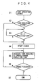
- the time-specified charge is carried out by the charger 8 of the charger unit 5 following the procedure from steps B1 to B7 in FIG. 4.
- B2 Whether it is the time-specified charge or not is checked, and if it is one of the other charge modes, it immediately proceeds to B4 and starts charge. If it is the time-specified charge, it proceeds to B3.
- B3 It obtains present time information from the timer 4, compares it with the specified charge starting time that is stored, and waits until the specified time. When the present time corresponds to the charge starting time, it proceeds to B4.
- the charger 8 turns ON either switch 19 or 20 according to the switch control signal S2, selects the battery unit 2 or 3 to be charged, and supplies charge electric power to the secondary battery 2B or 3B of the selected battery unit to start the charge.
- B5 At the time of starting the charge, it displays the time required to charge obtained at the setting of the charge time specified charge and/or charge completion time, and as the charge proceeds, it calculates the charging time as a value which is found by adding charged capacity to the remaining capacity to indicate the time taken before the completion of the charge and /or charge completion time in succession.
- B6, B7 Thereafter, it checks the completion of the charge, if the charge is not finished, it continues the charge in B5, and if it confirms the completion of the charge, it finishes the charge processing.
- one of the battery units 2 and 3 is selected and its secondary battery is charged, but if two of the battery units 2 and 3 need to be charged, one of the secondary batteries is charged and thereafter the other of the secondary batteries is selected and charged. At this time, it is natural that the time required to charge is what is found by adding up the times required to charge of the respective secondary batteries.
- the memory effect means that the capacity of the battery decreases after it is used by repeating charge and discharge in a state of a shallow charge depth.
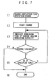
- the action in this case is conducted by the charger 8 following the procedure from steps C1 to C 10 in FIG. 5.
- C2 C3: First, it checks whether it is the time-specified charge or not, and if it is one of the other charge modes, it proceeds to C4 immediately and starts refresh. If it is the time-specified charge, it obtains the present time information from the timer 4 in C3 and compares it with the specified charge starting time that is stored. When the present time corresponds to the charge starting time, it proceeds to C4 and starts refresh.
- C4 It starts refresh. Specifically, the charger 8 turns ON either the switch 19 or 20 according to the switch control signal S2, selects either the battery unit 2 or 3, connects the secondary battery 2B or 3B to the discharger 15 and makes it discharge, whereby refresh is conducted.
- constant-current discharge constant-electric-power discharge, constant-resistance discharge and the like can be considered as discharge of the discharger 15, and in this explanation, constant-current discharge is adopted.
- refreshing time is calculated as a value obtained by subtracting a discharged capacity from a remaining capacity, and a period (of time) display and/or a time display are renewed in succession.
- C6 During execution of the refresh, the charger 8 obtains information from the measuring means 16 and 17 via the system bus 26, and checks the completion of the refresh action according to predetermined conditions by the battery properties. Discharge is continued in C5 until the refresh is finished, and when the refresh is finished, it proceeds to C7.
- C7 It supplies charge electric power to the refreshed secondary battery 2B or 3B to start charge.
- C8 At the time of starting the charge, it first indicates an obtained required time to charge and/or a charge completion time, and as the charge proceeds, it calculates the required time to charge from a value that is found by adding a charge capacity to the remaining capacity to renew the indication of the charging time and/or the charge completion time in succession.
- one of the battery units 2 and 3 is selected, and its secondary battery 2B or 3B is charged after being refreshed, but when both of the secondary batteries 2B and 3B of the two battery units 2 and 3 need to be charged after refresh, one of the secondary batteries is charged after the refresh, and thereafter the other battery unit is selected and its secondary battery is charged after the refresh.
- the refreshing time and the required time to charge is the result of adding up the refreshing times and the required times to charge of the two secondary batteries.
- D1 Go into setting of the charge mode by a predetermined operation on the display and operation unit 13.
- D4 It obtains remaining capacity information from the memory 11 or 12 of the battery unit 2 or 3 via the system bus 26, and present time information from the timer 4. Subsequently, it calculates chargeable time from the present time, and obtains a remaining capacity at the completion time.
- Remaining capacity remaining capacity + charge current ⁇ chargeable time (The maximum remaining capacity is the battery capacity, and if it is exceeded, the charge is finished.)
- the remaining capacity (charged capacity) at the time of completion of the constant-current charge is previously checked, and a time to remaining capacity (charged capacity) relation at the time of the constant-voltage charge is checked and tabulated.
- Remaining capacity T 1 remaining capacity at start of charge + charge current ⁇ T 1
- Charged capacity charged capacity in chargeable time - T 1 is calculated from the table .
- Remaining capacity remaining capacity T 1 + charge capacity (The maximum remaining capacity is the battery capacity, and if it is exceeded, the charge is finished.)
- Remaining capacity remaining capacity ( T 1 ) + charged capacity (The maximum remaining capacity is the battery capacity, and if it is exceeded, the charge is finished.)
- the remaining capacity calculated as above is indicated on the display and operation unit 13.
- E2 It starts charge. Specifically, the charger 8 turns ON either the switch 19 or 20 according to the switch control signal, selects either the battery unit 2 or 3, and its secondary battery 2B or 3B is connected to start the charge.
- E3 During the charge, it indicates remaining time of the charge obtained from the specified completion time and the present time, and/or the remaining capacity (obtained by the same method as explained about the charge completion time setting based on the elapsed time) changed according to the elapsed charge time.
- E4, E5, E6 The charger 8 checks the completion of the charge in E4, and when the charge is completed, it proceeds to E6 to finish the charge. When the charge is not completed, it compares the specified charge completion time and the present time in E5, and when it is the charge completion time (specified time), it proceeds to E6 to finish the charge. If it is not the charge completion time (specified time), it returns to E3 to continue the charge.
- one of the battery units 2 and 3 is selected and its secondary battery 2B or 3B is charged, but when both of the secondary batteries 2B and 3B of the two battery units 2 and 3 need to be charged, one of the secondary batteries is charged and thereafter the other battery unit is selected to charge the secondary battery. At this time, the remaining capacity is indicated for each battery unit.
- the time from which refreshing time is excluded may be the chargeable time.
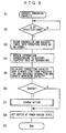
- the electric device 1 is in a power-saving state except for charge action and operating state and action of the timer function, and reduction in the remaining capacity of the secondary batteries 2B and 3B is decreased as much as possible.
- the timer 4 determines whether it is a specified time (specified elapsed time is acceptable) or not, and when it is the specified time, it outputs the wake-up signal WU.
- the controller 6 starts action according to the wake-up signal WU, and brings the related parts, for example, the measuring means 16 and 17 into an operating state.
- the controller 6 obtains information necessary for the remaining capacity correction according to the properties of the secondary battery such as temperature and the like from the measuring means 16 and 17, the memories 11 and 12 and the like via the system bus 26.
- F5 It calculates the correction capacity from the elapsed time from the previous correction and the obtained information, and the remaining capacity of the secondary batteries 2B and 3B is corrected. For example, if self-discharge of the secondary batteries 2B and 3B is determined by time and temperature, the average value of the previous temperature and obtained temperature is taken, and self-discharge amount is found from the relation with time based on the information previously stored in the memories 11 and 12 and the like, whereby correction information is obtained.
- a used capacity of the secondary battery in the power-saving state is found based on the used electric power and elapsed time in the power-saving state, and the value of the remaining capacity stored in the memories 11 and 12 is corrected with the above-described self-discharge amount and the used capacity in this action.
- the charger 8 of the charger unit 5 needs to be supplied with electric power from the commercial power supply 14 or an alternative power supply.
- Steps G1 to G5 are the same as steps F1 to F5 explained in FIG. 8.
- G6 to G9 After the remaining capacity is corrected in G5, whether charge is necessary or not is determined by the determination of whether the remaining capacity is not more than a capacity set in advance in G6. If the capacity exceeds the set capacity, charge is determined as unnecessary to proceed to G8, and the electric device is set at the power-saving state again, and the action is finished in G9.
- the capacity is not more than the set capacity, charge is determined as necessary, then charge action is carried out until the remaining capacity becomes the predetermined remaining capacity in G7, then after the remaining capacity is stored in the memory 11 or 12 as the remaining capacity of the battery at the point of time of completion of the charge, the electric device 1 is set at the power-saving state in G8, and the action is finished in G9.
- the electric device of an electric vehicle or the like makes it possible to improve accuracy with which a remaining capacity of the secondary battery is grasped and to charge the secondary battery at appropriate times. Further, start of charge by specifying time, charge by specifying the charge completion time or calculation and indication of the charge completion time, automatic refresh and automatic charge of the secondary battery, and the like can be made, and controlling accuracy and handling ease of the secondary battery especially in an electric vehicle can be improved.
Abstract
Claims (8)
- Dispositif électrique (1) d'un véhicule électrique avec un minuteur (4), comprenant :une batterie secondaire rechargeable (2B, 3B) ;un moyen de mesure (16, 17) pour mesurer un état de ladite batterie secondaire (2B, 3B), et une mémoire (11, 12) pour stocker les informations mesurées de celle-ci et les informations relatives aux propriétés de ladite batterie secondaire (2B, 3B) ;une charge (10) d'un moteur électrique entraînée par une alimentation électrique fournie par ladite batterie secondaire (2B, 3B) ;un système de commande (6) pour commander l'entraînement de ladite charge (10) ;un minuteur (4) ayant une fonction de minuteur ;une unité d'affichage et d'utilisation (13) ayant une fonction de réglage de durée pour ledit minuteur (4) et une fonction d'affichage de la durée ;un système de gestion de batterie pour gérer ladite batterie secondaire (2B, 3B) sur la base des informations dudit moyen de mesure (16, 17) et/ou de ladite mémoire (11, 12) et des informations de durée dudit minuteur (4) ; etune interface (169) capable de connecter un chargeur (8) via un bus système (26) pour charger ladite batterie secondaire (2B, 3B) sur la base des informations dudit moyen de mesure (16, 17) et/ou de ladite mémoire (11, 12) et des informations de durée dudit minuteur (4).
- Dispositif électrique selon la revendication 1, dans lequel
ledit système de commande (6) a également une fonction de dit système de gestion de batterie pour gérer ladite batterie secondaire (2B, 3B) sur la base des informations dudit moyen de mesure (16, 17) et/ou de ladite mémoire (11, 12) et des informations de durée dudit minuteur (4). - Dispositif électrique (1) d'un véhicule électrique avec un minuteur (4), comprenant :une batterie secondaire rechargeable (2B, 3B) ;un moyen de mesure (16, 17) pour mesurer un état de ladite batterie secondaire (2B, 3B), et une mémoire (11, 12) pour stocker les informations mesurées de celle-ci et les informations relatives aux propriétés de ladite batterie secondaire (2B, 3B) ;une charge (10) d'un moteur électrique entraînée par une alimentation électrique fournie par ladite batterie secondaire (2B, 3B) ;un système de commande (6) pour commander l'entraînement de ladite charge (10) ;un minuteur (4) ayant une fonction de minuteur ;une unité d'affichage et d'utilisation (13) ayant une fonction de réglage de durée pour ledit minuteur (4) et une fonction d'affichage de la durée ;un chargeur (8) pour charger ladite batterie secondaire (2B, 3B) sur la base des informations dudit moyen de mesure (16, 17) et/ou de ladite mémoire (11, 12) et des informations de durée dudit minuteur (4) ; etune interface (169) pour connecter ledit chargeur (8) avec ledit moyen de mesure (16, 17) et/ou ladite mémoire (11, 12) et ledit minuteur (4) et ledit système de commande (6) via un bus système (26)
- Dispositif électrique selon la revendication 3, dans lequel
ledit système de commande (6) a également une fonction de système de gestion de batterie pour gérer ladite batterie secondaire (2B, 3B) sur la base des informations dudit moyen de mesure (16, 17) et/ou de ladite mémoire (11, 12) et des informations de durée dudit minuteur (4). - Dispositif électrique selon la revendication 1 ou 3, dans lequel
ladite batterie secondaire (2B, 3B), ledit moyen de mesure (16, 17) et ladite mémoire (11, 12) sont constitués de manière à être une unité de batterie intégrée (2, 3), et l'unité de batterie intégrée (2, 3) est montée sur un corps principal de dispositif électrique de façon à être attachable/détachable à celui-ci/de celui-ci. - Dispositif électrique selon la revendication 4 dans lequel
ladite unité d'affichage et d'utilisation (13) est dotée d'un moyen de spécification de temps pour spécifier un moment de fin de charge, et ledit chargeur (8) est doté d'un moyen de lancement de charge de sorte que la charge de ladite batterie secondaire (2B, 3B) est terminée à un moment spécifié par le moyen de spécification de temps. - Dispositif électrique selon la revendication 1 ou 3, comprenant en outre :un moyen actionné à un moment spécifié par ledit minuteur (4), faisant fonctionner ledit moyen de mesure (16, 17) et ladite mémoire (11, 12), et gérant une capacité résiduelle de ladite batterie secondaire (2B, 3B) sur la base d'une quantité d'auto-décharge et d'une capacité de consommation selon les propriétés de ladite batterie secondaire (2B, 3B).
- Dispositif électrique selon la revendication 3 ou 4, comprenant en outre :un moyen actionné à un moment spécifié par ledit minuteur (4), faisant fonctionner ledit moyen de mesure (16, 17) et ladite mémoire (11, 12), gérant une capacité résiduelle de ladite batterie secondaire (2B, 3B) sur la base d'une quantité d'auto-décharge et d'une capacité de consommation selon les propriétés de ladite batterie secondaire (2B, 3B), et faisant en sorte que ledit chargeur (8) charge ladite batterie secondaire (2B, 3B) lorsqu'elle nécessite d'être chargée.
Applications Claiming Priority (3)
| Application Number | Priority Date | Filing Date | Title |
|---|---|---|---|
| JP25338999A JP2001076764A (ja) | 1999-09-07 | 1999-09-07 | 時計手段を有する電動装置 |
| JP25338999 | 1999-09-07 | ||
| PCT/JP2000/005925 WO2001018899A1 (fr) | 1999-09-07 | 2000-08-31 | Appareil electrique equipe d'un dispositif de minuterie |
Publications (3)
| Publication Number | Publication Date |
|---|---|
| EP1220350A1 EP1220350A1 (fr) | 2002-07-03 |
| EP1220350A4 EP1220350A4 (fr) | 2004-07-21 |
| EP1220350B1 true EP1220350B1 (fr) | 2006-12-06 |
Family
ID=17250700
Family Applications (1)
| Application Number | Title | Priority Date | Filing Date |
|---|---|---|---|
| EP00956848A Expired - Lifetime EP1220350B1 (fr) | 1999-09-07 | 2000-08-31 | Appareil electrique equipe d'un dispositif de minuterie |
Country Status (7)
| Country | Link |
|---|---|
| EP (1) | EP1220350B1 (fr) |
| JP (1) | JP2001076764A (fr) |
| KR (1) | KR100441318B1 (fr) |
| CN (1) | CN1182619C (fr) |
| CA (1) | CA2387714A1 (fr) |
| DE (1) | DE60032251T2 (fr) |
| WO (1) | WO2001018899A1 (fr) |
Families Citing this family (16)
| Publication number | Priority date | Publication date | Assignee | Title |
|---|---|---|---|---|
| JP3964635B2 (ja) * | 2001-06-20 | 2007-08-22 | 松下電器産業株式会社 | メモリー効果の検出方法およびその解消方法 |
| DE10228806B3 (de) * | 2002-06-27 | 2004-03-04 | Fraunhofer-Gesellschaft zur Förderung der angewandten Forschung e.V. | Einrichtung und Verfahren zum Bestimmen eines Ladezustands einer Batterie |
| JP4306775B2 (ja) * | 2007-08-31 | 2009-08-05 | トヨタ自動車株式会社 | 電動車両 |
| JP2009100569A (ja) * | 2007-10-17 | 2009-05-07 | Toyota Motor Corp | 車両および充電ケーブル |
| JP2009296824A (ja) * | 2008-06-06 | 2009-12-17 | Toyota Industries Corp | 充電システム |
| WO2010022059A1 (fr) | 2008-08-18 | 2010-02-25 | Austin Christopher B | Chargeur de batterie de véhicule, système de charge, et procédé |
| DE102009003873A1 (de) * | 2009-05-04 | 2010-11-18 | Paade Gmbh | Verfahren und Vorrichtung zum Aufladen von Akkumulatoren |
| JP5349243B2 (ja) * | 2009-10-09 | 2013-11-20 | 中国電力株式会社 | 電気自動車充電システム及び電気自動車充電方法 |
| JP2011142036A (ja) * | 2010-01-08 | 2011-07-21 | Sanyo Electric Co Ltd | 電池管理方法および電子機器 |
| JP5699702B2 (ja) * | 2011-03-11 | 2015-04-15 | 日産自動車株式会社 | 車両の充電制御装置 |
| JP5679055B2 (ja) * | 2011-06-10 | 2015-03-04 | トヨタ自動車株式会社 | 電池の充電方法、及び電池の充電制御装置 |
| CN102303541B (zh) * | 2011-06-20 | 2013-01-09 | 安徽安凯汽车股份有限公司 | 一种增程式电动汽车的蓄电池电量管理方法 |
| JP5787153B2 (ja) * | 2011-09-08 | 2015-09-30 | スズキ株式会社 | 車載充電システム |
| JP5974108B2 (ja) * | 2012-10-01 | 2016-08-23 | 日立オートモティブシステムズ株式会社 | 電動車両の制御装置 |
| CN105128999A (zh) * | 2015-09-30 | 2015-12-09 | 浙江绿源电动车有限公司 | 电动车及终端 |
| CN114523860A (zh) * | 2020-11-23 | 2022-05-24 | 长城汽车股份有限公司 | 一种充电控制方法、装置、电子设备及可读存储介质 |
Family Cites Families (6)
| Publication number | Priority date | Publication date | Assignee | Title |
|---|---|---|---|---|
| JPH05153733A (ja) * | 1991-04-17 | 1993-06-18 | Hitachi Ltd | 2次電池電源装置及び2次電池駆動の電子機器 |
| JPH07194017A (ja) * | 1993-12-24 | 1995-07-28 | Canon Inc | 充電器 |
| JPH08138748A (ja) * | 1994-11-15 | 1996-05-31 | Canon Inc | 二次電池の充電装置および二次電池の充電制御方法 |
| JPH1138106A (ja) * | 1997-07-16 | 1999-02-12 | Oki Electric Ind Co Ltd | 電子装置 |
| JPH11136870A (ja) * | 1997-10-24 | 1999-05-21 | Sharp Corp | 電子機器 |
| DE19834740C2 (de) * | 1998-08-01 | 2003-03-13 | Iq Battery Res & Dev Gmbh | Kraftfahrzeugbatterie mit integrierter Überwachungsvorrichtung und Verfahren zur Überwachung einer Kraftfahrzeugbatterie |
-
1999
- 1999-09-07 JP JP25338999A patent/JP2001076764A/ja active Pending
-
2000
- 2000-08-31 KR KR10-2002-7002590A patent/KR100441318B1/ko not_active IP Right Cessation
- 2000-08-31 CA CA002387714A patent/CA2387714A1/fr not_active Abandoned
- 2000-08-31 CN CNB008125163A patent/CN1182619C/zh not_active Expired - Fee Related
- 2000-08-31 EP EP00956848A patent/EP1220350B1/fr not_active Expired - Lifetime
- 2000-08-31 DE DE60032251T patent/DE60032251T2/de not_active Expired - Fee Related
- 2000-08-31 WO PCT/JP2000/005925 patent/WO2001018899A1/fr active IP Right Grant
Also Published As
| Publication number | Publication date |
|---|---|
| CA2387714A1 (fr) | 2001-03-15 |
| CN1182619C (zh) | 2004-12-29 |
| DE60032251T2 (de) | 2007-04-05 |
| CN1372707A (zh) | 2002-10-02 |
| EP1220350A1 (fr) | 2002-07-03 |
| EP1220350A4 (fr) | 2004-07-21 |
| JP2001076764A (ja) | 2001-03-23 |
| KR20020053058A (ko) | 2002-07-04 |
| WO2001018899A1 (fr) | 2001-03-15 |
| DE60032251D1 (de) | 2007-01-18 |
| KR100441318B1 (ko) | 2004-07-23 |
Similar Documents
| Publication | Publication Date | Title |
|---|---|---|
| EP1220350B1 (fr) | Appareil electrique equipe d'un dispositif de minuterie | |
| JP4486046B2 (ja) | バッテリパックのモニタリング装置及びその方法 | |
| US6836122B2 (en) | Deterioration degree calculating apparatus and deterioration degree calculating method for a battery | |
| US8957636B2 (en) | Vehicle battery-pack equalization system and vehicle battery-pack equalization method | |
| CN102439780B (zh) | 二次电池的劣化度计算装置、搭载该装置的车辆以及二次电池的劣化度计算方法 | |
| US5952813A (en) | Battery charging system and electric vehicle with battery charging system | |
| US5739671A (en) | Device for accurate detection of remaining discharge capacities of a plurality of batteries | |
| JP3929243B2 (ja) | 電動車両用電源システム | |
| JPH0933623A (ja) | バッテリー容量計 | |
| JP2001076764A5 (fr) | ||
| JPH10164764A (ja) | 電池容量監視方法 | |
| JP3420683B2 (ja) | バッテリ充電装置 | |
| JP3934268B2 (ja) | 電動車両用電源システム | |
| JP2011038878A (ja) | 二次電池の劣化度判定方法および二次電池装置 | |
| JPH06105476A (ja) | 電池充電装置 | |
| JP4562214B2 (ja) | 着脱式電池パックの充電制御装置 | |
| JP2003009417A (ja) | バッテリ充電装置及びそのバッテリ充電装置を装着したバッテリフォークリフト | |
| JP4960656B2 (ja) | 電池制御装置およびプログラム | |
| JP3695727B2 (ja) | 充電制御方法および充電装置 | |
| JP2000100477A (ja) | 電動車両の電池状態表示装置 | |
| JP4064585B2 (ja) | 電動車両用電源システム | |
| JP3989979B2 (ja) | 二次電池のテスター | |
| JP3734940B2 (ja) | バッテリー用管理装置 | |
| JPH11122827A (ja) | 充電器 | |
| JP2001238361A (ja) | アダプタ |
Legal Events
| Date | Code | Title | Description |
|---|---|---|---|
| PUAI | Public reference made under article 153(3) epc to a published international application that has entered the european phase |
Free format text: ORIGINAL CODE: 0009012 |
|
| 17P | Request for examination filed |
Effective date: 20020318 |
|
| AK | Designated contracting states |
Kind code of ref document: A1 Designated state(s): AT BE CH CY DE DK ES FI FR GB GR IE IT LI LU MC NL PT SE |
|
| AX | Request for extension of the european patent |
Free format text: AL;LT;LV;MK;RO;SI |
|
| RIN1 | Information on inventor provided before grant (corrected) |
Inventor name: OHNUMA, NOBUHITO, TOKYO R&D CO., LTD., Inventor name: AOKI, TAKASHI Inventor name: ISHII, HIROSHI |
|
| RBV | Designated contracting states (corrected) |
Designated state(s): DE ES FR IT PT |
|
| A4 | Supplementary search report drawn up and despatched |
Effective date: 20040609 |
|
| 17Q | First examination report despatched |
Effective date: 20041013 |
|
| GRAP | Despatch of communication of intention to grant a patent |
Free format text: ORIGINAL CODE: EPIDOSNIGR1 |
|
| GRAS | Grant fee paid |
Free format text: ORIGINAL CODE: EPIDOSNIGR3 |
|
| GRAA | (expected) grant |
Free format text: ORIGINAL CODE: 0009210 |
|
| AK | Designated contracting states |
Kind code of ref document: B1 Designated state(s): DE ES FR IT PT |
|
| REF | Corresponds to: |
Ref document number: 60032251 Country of ref document: DE Date of ref document: 20070118 Kind code of ref document: P |
|
| PG25 | Lapsed in a contracting state [announced via postgrant information from national office to epo] |
Ref country code: ES Free format text: LAPSE BECAUSE OF FAILURE TO SUBMIT A TRANSLATION OF THE DESCRIPTION OR TO PAY THE FEE WITHIN THE PRESCRIBED TIME-LIMIT Effective date: 20070317 |
|
| PG25 | Lapsed in a contracting state [announced via postgrant information from national office to epo] |
Ref country code: PT Free format text: LAPSE BECAUSE OF FAILURE TO SUBMIT A TRANSLATION OF THE DESCRIPTION OR TO PAY THE FEE WITHIN THE PRESCRIBED TIME-LIMIT Effective date: 20070507 |
|
| ET | Fr: translation filed | ||
| PGFP | Annual fee paid to national office [announced via postgrant information from national office to epo] |
Ref country code: DE Payment date: 20070823 Year of fee payment: 8 |
|
| PLBE | No opposition filed within time limit |
Free format text: ORIGINAL CODE: 0009261 |
|
| STAA | Information on the status of an ep patent application or granted ep patent |
Free format text: STATUS: NO OPPOSITION FILED WITHIN TIME LIMIT |
|
| 26N | No opposition filed |
Effective date: 20070907 |
|
| PGFP | Annual fee paid to national office [announced via postgrant information from national office to epo] |
Ref country code: IT Payment date: 20070830 Year of fee payment: 8 |
|
| PGFP | Annual fee paid to national office [announced via postgrant information from national office to epo] |
Ref country code: FR Payment date: 20070808 Year of fee payment: 8 |
|
| REG | Reference to a national code |
Ref country code: FR Ref legal event code: ST Effective date: 20090430 |
|
| PG25 | Lapsed in a contracting state [announced via postgrant information from national office to epo] |
Ref country code: IT Free format text: LAPSE BECAUSE OF NON-PAYMENT OF DUE FEES Effective date: 20080831 Ref country code: FR Free format text: LAPSE BECAUSE OF NON-PAYMENT OF DUE FEES Effective date: 20080901 Ref country code: DE Free format text: LAPSE BECAUSE OF NON-PAYMENT OF DUE FEES Effective date: 20090303 |