EP1219846A2 - Verfahren zum Rückstellen einer elektromechanischen Axialverstellvorrichtung - Google Patents
Verfahren zum Rückstellen einer elektromechanischen Axialverstellvorrichtung Download PDFInfo
- Publication number
- EP1219846A2 EP1219846A2 EP01127988A EP01127988A EP1219846A2 EP 1219846 A2 EP1219846 A2 EP 1219846A2 EP 01127988 A EP01127988 A EP 01127988A EP 01127988 A EP01127988 A EP 01127988A EP 1219846 A2 EP1219846 A2 EP 1219846A2
- Authority
- EP
- European Patent Office
- Prior art keywords
- electric motor
- adjustment device
- axial adjustment
- axial
- voltage
- Prior art date
- Legal status (The legal status is an assumption and is not a legal conclusion. Google has not performed a legal analysis and makes no representation as to the accuracy of the status listed.)
- Granted
Links
Images


Classifications
-
- F—MECHANICAL ENGINEERING; LIGHTING; HEATING; WEAPONS; BLASTING
- F16—ENGINEERING ELEMENTS AND UNITS; GENERAL MEASURES FOR PRODUCING AND MAINTAINING EFFECTIVE FUNCTIONING OF MACHINES OR INSTALLATIONS; THERMAL INSULATION IN GENERAL
- F16H—GEARING
- F16H48/00—Differential gearings
- F16H48/20—Arrangements for suppressing or influencing the differential action, e.g. locking devices
- F16H48/22—Arrangements for suppressing or influencing the differential action, e.g. locking devices using friction clutches or brakes
-
- B—PERFORMING OPERATIONS; TRANSPORTING
- B60—VEHICLES IN GENERAL
- B60W—CONJOINT CONTROL OF VEHICLE SUB-UNITS OF DIFFERENT TYPE OR DIFFERENT FUNCTION; CONTROL SYSTEMS SPECIALLY ADAPTED FOR HYBRID VEHICLES; ROAD VEHICLE DRIVE CONTROL SYSTEMS FOR PURPOSES NOT RELATED TO THE CONTROL OF A PARTICULAR SUB-UNIT
- B60W10/00—Conjoint control of vehicle sub-units of different type or different function
- B60W10/12—Conjoint control of vehicle sub-units of different type or different function including control of differentials
-
- F—MECHANICAL ENGINEERING; LIGHTING; HEATING; WEAPONS; BLASTING
- F16—ENGINEERING ELEMENTS AND UNITS; GENERAL MEASURES FOR PRODUCING AND MAINTAINING EFFECTIVE FUNCTIONING OF MACHINES OR INSTALLATIONS; THERMAL INSULATION IN GENERAL
- F16D—COUPLINGS FOR TRANSMITTING ROTATION; CLUTCHES; BRAKES
- F16D27/00—Magnetically- or electrically- actuated clutches; Control or electric circuits therefor
- F16D27/10—Magnetically- or electrically- actuated clutches; Control or electric circuits therefor with an electromagnet not rotating with a clutching member, i.e. without collecting rings
- F16D27/108—Magnetically- or electrically- actuated clutches; Control or electric circuits therefor with an electromagnet not rotating with a clutching member, i.e. without collecting rings with axially movable clutching members
- F16D27/112—Magnetically- or electrically- actuated clutches; Control or electric circuits therefor with an electromagnet not rotating with a clutching member, i.e. without collecting rings with axially movable clutching members with flat friction surfaces, e.g. discs
- F16D27/115—Magnetically- or electrically- actuated clutches; Control or electric circuits therefor with an electromagnet not rotating with a clutching member, i.e. without collecting rings with axially movable clutching members with flat friction surfaces, e.g. discs with more than two discs, e.g. multiple lamellae
-
- F—MECHANICAL ENGINEERING; LIGHTING; HEATING; WEAPONS; BLASTING
- F16—ENGINEERING ELEMENTS AND UNITS; GENERAL MEASURES FOR PRODUCING AND MAINTAINING EFFECTIVE FUNCTIONING OF MACHINES OR INSTALLATIONS; THERMAL INSULATION IN GENERAL
- F16D—COUPLINGS FOR TRANSMITTING ROTATION; CLUTCHES; BRAKES
- F16D28/00—Electrically-actuated clutches
-
- F—MECHANICAL ENGINEERING; LIGHTING; HEATING; WEAPONS; BLASTING
- F16—ENGINEERING ELEMENTS AND UNITS; GENERAL MEASURES FOR PRODUCING AND MAINTAINING EFFECTIVE FUNCTIONING OF MACHINES OR INSTALLATIONS; THERMAL INSULATION IN GENERAL
- F16H—GEARING
- F16H48/00—Differential gearings
- F16H48/20—Arrangements for suppressing or influencing the differential action, e.g. locking devices
- F16H48/295—Arrangements for suppressing or influencing the differential action, e.g. locking devices using multiple means for force boosting
-
- F—MECHANICAL ENGINEERING; LIGHTING; HEATING; WEAPONS; BLASTING
- F16—ENGINEERING ELEMENTS AND UNITS; GENERAL MEASURES FOR PRODUCING AND MAINTAINING EFFECTIVE FUNCTIONING OF MACHINES OR INSTALLATIONS; THERMAL INSULATION IN GENERAL
- F16H—GEARING
- F16H48/00—Differential gearings
- F16H48/20—Arrangements for suppressing or influencing the differential action, e.g. locking devices
- F16H48/30—Arrangements for suppressing or influencing the differential action, e.g. locking devices using externally-actuatable means
- F16H48/34—Arrangements for suppressing or influencing the differential action, e.g. locking devices using externally-actuatable means using electromagnetic or electric actuators
-
- F—MECHANICAL ENGINEERING; LIGHTING; HEATING; WEAPONS; BLASTING
- F16—ENGINEERING ELEMENTS AND UNITS; GENERAL MEASURES FOR PRODUCING AND MAINTAINING EFFECTIVE FUNCTIONING OF MACHINES OR INSTALLATIONS; THERMAL INSULATION IN GENERAL
- F16H—GEARING
- F16H63/00—Control outputs from the control unit to change-speed- or reversing-gearings for conveying rotary motion or to other devices than the final output mechanism
- F16H63/02—Final output mechanisms therefor; Actuating means for the final output mechanisms
- F16H63/30—Constructional features of the final output mechanisms
- F16H63/304—Constructional features of the final output mechanisms the final output mechanisms comprising elements moved by electrical or magnetic force
- F16H63/3043—Constructional features of the final output mechanisms the final output mechanisms comprising elements moved by electrical or magnetic force comprising friction clutches or brakes
-
- F—MECHANICAL ENGINEERING; LIGHTING; HEATING; WEAPONS; BLASTING
- F16—ENGINEERING ELEMENTS AND UNITS; GENERAL MEASURES FOR PRODUCING AND MAINTAINING EFFECTIVE FUNCTIONING OF MACHINES OR INSTALLATIONS; THERMAL INSULATION IN GENERAL
- F16D—COUPLINGS FOR TRANSMITTING ROTATION; CLUTCHES; BRAKES
- F16D27/00—Magnetically- or electrically- actuated clutches; Control or electric circuits therefor
- F16D27/004—Magnetically- or electrically- actuated clutches; Control or electric circuits therefor with permanent magnets combined with electromagnets
-
- F—MECHANICAL ENGINEERING; LIGHTING; HEATING; WEAPONS; BLASTING
- F16—ENGINEERING ELEMENTS AND UNITS; GENERAL MEASURES FOR PRODUCING AND MAINTAINING EFFECTIVE FUNCTIONING OF MACHINES OR INSTALLATIONS; THERMAL INSULATION IN GENERAL
- F16H—GEARING
- F16H48/00—Differential gearings
- F16H48/20—Arrangements for suppressing or influencing the differential action, e.g. locking devices
- F16H48/30—Arrangements for suppressing or influencing the differential action, e.g. locking devices using externally-actuatable means
- F16H48/34—Arrangements for suppressing or influencing the differential action, e.g. locking devices using externally-actuatable means using electromagnetic or electric actuators
- F16H2048/343—Arrangements for suppressing or influencing the differential action, e.g. locking devices using externally-actuatable means using electromagnetic or electric actuators using a rotary motor
-
- Y—GENERAL TAGGING OF NEW TECHNOLOGICAL DEVELOPMENTS; GENERAL TAGGING OF CROSS-SECTIONAL TECHNOLOGIES SPANNING OVER SEVERAL SECTIONS OF THE IPC; TECHNICAL SUBJECTS COVERED BY FORMER USPC CROSS-REFERENCE ART COLLECTIONS [XRACs] AND DIGESTS
- Y10—TECHNICAL SUBJECTS COVERED BY FORMER USPC
- Y10T—TECHNICAL SUBJECTS COVERED BY FORMER US CLASSIFICATION
- Y10T74/00—Machine element or mechanism
- Y10T74/19—Gearing
- Y10T74/19219—Interchangeably locked
- Y10T74/19284—Meshing assisters
- Y10T74/19288—Double clutch and interposed transmission
Definitions
- the invention further relates to an electromechanical axial adjustment device to carry out the procedure.
- Axial adjustment devices of the type mentioned are simply constructed, have a compact design and short response times, as they e.g. B. for friction clutches in limited slip differentials required are.
- Applications of these referred to as “Powr-Lok®" Adjustment devices are in DE 39 20 861 C2, DE 39 15 959 C2, DE 39 09 112 C2, DE 38 15 225 C2 and DE 100 33 482.2 It has already been pointed out several times there been that to achieve compatibility of the so equipped Limited slip differentials with vehicles with ABS systems and / or the ability to reset quickly with ESP systems of these axial adjustment devices is necessary.
- a such a reset is effected by return springs which either as a spiral spring directly the twisted collar turn back and thereby come back the axially shifted collar let or as axial springs with self-locking Groove arrangements push back the axially displaced adjusting ring and thereby turn back the twisted collar.
- a device must have a voltage reversal circuit for the electric motor and a motor speed detection circuit for the electric motor that include each other so logical about the idle speed of the electric motor are interconnected that the voltage reversing circuit is separated when idling speed when resetting the device of the electric motor is reached.
- Axial adjustment devices of the type mentioned in particular those caused by reinforced return springs or by circuit arrangements for voltage reversal to a fast return designed for a quick disconnection of the friction clutch experience a hard impact at the end of the rewind hitting the balls at the groove ends of the ball grooves the collars.
- This shock is so violent that it viewed in vehicles as an impermissible impairment of comfort becomes. He also guides the unprepared driver to uncertainty, since this the violent shock as a damage will interpret.
- a suitable device comprises a rotary position sensor which is connected to a rotating one Part, e.g. B.
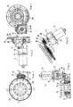
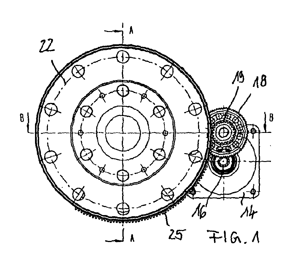
- FIG. 1 to 5 are largely described together.
- An electric motor 11 is connected to a first flange plate 12 screwed to a bearing block 13, the second flange plate 14 forms.
- the bearing block 13 is an extension of the Motor shaft 15 mounted, which carries a first pinion 16.
- Bearing block 13 is also a secondary shaft 17 which carries a further pinion 18 which meshes with the pinion 16 and a further pinion 19 to form a reduction stage wearing.
- the bearing block 13 is on the bearing flange 14 z. B. on to attach a gearbox.
- With parallel axis to The motor axis is a bearing sleeve 21 with a flange plate 22 shown, which are rotatably mounted in the gear housing can.
- a first adjusting ring 23 is on the bearing sleeve 21 a radial bearing 24 is mounted.
- the collar 23 includes a toothed segment 25.
- the pinion 19 of the auxiliary shaft 17 is in the Gearing engagement with the toothed segment 25 of the first adjusting ring 23.
- Parallel to the first collar 23 is another Adjustment ring 26 with a retaining lug 27 with the gear housing can be in a rotationally fixed engagement.
- Between the collars 23, 26 are a plurality of in a cage 28 balls 29, by means of which the second adjusting ring 26 is centered on the first adjusting ring 23.
- the first collar 23 is supported on a disk 32 via an axial bearing 31, fixed with a retaining ring 33 on the bearing sleeve 21 is.
- the second collar is supported by an axial bearing 34 on a pressure plate 35, which via plate spring assemblies 36 is held in the flange plate 22.
- the pressure plate 35 acts at the same time on pressure pin 37, which the flange plate 22nd penetrate a. Ball grooves in the collars 23, 26, the balls 29 hold are as opposed to the circumference rising ramps executed.
- Driving the electric motor 11 rotates the toothed segment 25 and thus the first adjusting ring 23 opposite the second via the retaining lug 27 with the gear housing engaged collar 26, which thereby axially displaced against the restoring force of the plate springs 36 is applied and thus the pressure pin 37.
- the first adjusting ring 23 with the toothed segment 25 shows in its an end face five with a pitch angle of 72 ° circumferentially distributed ball grooves 41 each 58 ° in circumferential length. As shown in Figure 8, the ball grooves a pitch angle of 1.5 ° over its circumferential extent and thus a variable depth between two stops 42 and 43 for the balls 29. In the ball groove shown in section is the ball in its two stop positions shown in broken lines.
- the second adjusting ring 26 has five in its end face Ball grooves 44 on the with a pitch angle of 72 ° are distributed around the circumference and have a circumferential length of 58 °.
- the holding lug 27 with a guide groove 47 is particularly designated.
- the ball grooves have, as in Figure 14 in detail is recognizable, a variable depth due to the circumference a pitch angle of 1.5 ° and have two stops 45, 46 for the balls 29. A ball is in its two Stop positions shown in dash-dotted lines.
- An adjustment device of the aforementioned type is on one Differential gear installed, which is a gearbox 51 has.
- the bearing sleeve 21 ' is in one piece in this case formed with a differential cage 52, which is in the differential gear is rotatably supported by roller bearings 53, 54.
- the bearing sleeve 21 ' is in one piece in this case formed with a differential cage 52, which is in the differential gear is rotatably supported by roller bearings 53, 54.
- the bevel gears are with differential bevel gears 59, 60 engaged.
- a friction clutch 61 includes first friction plates 63, which are rotatably connected to a sleeve 62 are, which is fixed on the axle shaft 55, and second Friction plates 64, which are rotatable with the differential cage 52 are connected.
- the friction clutch 61 is between one axially displaceable pressure plate 65 and one in the differential carrier 52 fixed support body 66 arranged.
- the pressure plate 65 is directly through the pressure pin 37 ' acted upon when the first adjusting ring is rotated 23 'relative to the second adjusting ring 26'.
- the second adjusting ring 26 ' engages in retaining lugs 27 Pins 67, 68 rotatably held in the differential gear case 51 are set.
- the electric motor is energized negatively (Active Disconnection), causing the engine speed to turn negative Values ramping up and the transmissible torque Opening the friction clutch decreases.
- the power is switched off for 0.01 seconds, so that the Time of 0.015 seconds the current in the electric motor becomes 0.
- the Switching off the power is selected so that after about this time the electric motor with approx. 200 rad./sec reached its nominal speed, so that the speed afterwards declines further due to the action of the disc springs can increase without this increase due to the induction counter voltage in the electric motor is braked.
- the transmissible torque drops up to a time of 0.095 seconds further.
- FIG 20 is the torque curve of the friction clutch (Transmitted torque) over the time axis as a result of the invention Interruption of negative current supply (active "optimum") compared to a permanent negative current supply (active "Standard”) and the backward running exclusively under Spring force (passive) shown. This is going backwards referred to as “passive” under spring force, which is recognizable causes the slowest reduction of the transmissible torque.
- active Standard there is a permanent negative current supply of the electric motor designated by the induction of a Internal tension from about 0.04 seconds to a significantly slowed down Reduction of the transferable torque leads while with "Active Optimum” is indicated a negative current, which when the idling speed is reached after approx. 0.04 seconds is interrupted again, so that as soon as possible The transferable torque decreases.
- Figure 22 are two of Figures 20 and 21, namely representation the transmitted torque and Representation of engine speed at reset (Rotational Speed Rotor), for a further advantageous control process shown, which is immediately before reaching the end stops the ball grooves play through the balls.
Landscapes
- Engineering & Computer Science (AREA)
- General Engineering & Computer Science (AREA)
- Mechanical Engineering (AREA)
- Physics & Mathematics (AREA)
- Electromagnetism (AREA)
- Chemical & Material Sciences (AREA)
- Combustion & Propulsion (AREA)
- Transportation (AREA)
- Retarders (AREA)
- Connection Of Motors, Electrical Generators, Mechanical Devices, And The Like (AREA)
- Braking Arrangements (AREA)
- Hydraulic Clutches, Magnetic Clutches, Fluid Clutches, And Fluid Joints (AREA)
- Transmission Devices (AREA)
- One-Way And Automatic Clutches, And Combinations Of Different Clutches (AREA)
- Friction Gearing (AREA)
- Arrangement And Mounting Of Devices That Control Transmission Of Motive Force (AREA)
Abstract
Description
- Figur 1
- zeigt eine erfindungsgemäße Axialverstellvorrichtung in einer ersten Axialansicht;
- Figur 2
- zeigt die Vorrichtung nach Figur 1 im Schnitt A-A;
- Figur 3
- zeigt die Vorrichtung nach Figur 1 in axialer Gegenansicht zu Figur 1;
- Figur 4
- zeigt die Vorrichtung nach Figur 1 im Schnitt B-B;
- Figur 5
- zeigt die Vorrichtung in der Darstellung nach Figur 4, jedoch in Ansicht;
- Figur 6
- zeigt einen drehend antreibbaren Stellring der Vorrichtung als Einzelheit in axialer Ansicht auf die Rillen;
- Figur 7
- zeigt den Stellring nach Figur 6 im Schnitt A-A;
- Figur 8
- zeigt einen Zylinderschnitt durch eine Rille in Vergrößerung;
- Figur 9
- zeigt die Einzelheit X aus Figur 7;
- Figur 10
- zeigt die Einzelheit Y aus Figur 7;
- Figur 11
- zeigt den Stellring nach Figur 6 in einer perspektivischen Ansicht;
- Figur 12
- zeigt den zweiten Stellring der Vorrichtung nach Figur 1 in Aufsicht auf die Stirnfläche mit den Rillen;
- Figur 13
- zeigt den Stellring nach Figur 12 im Schnitt A-A;
- Figur 14
- zeigt einen Zylinderschnitt durch eine Rille in Vergrößerung;
- Figur 15
- zeigt den Schnitt B-B aus Figur 12;
- Figur 16
- zeigt den Stellring nach Figur 12 in perspektivischer Schrägansicht;
- Figur 17
- zeigt eine erfindungsgemäße Stellvorrichtung in Verwendung mit einem Differentialgetriebe in einem Teilschnitt;
- Figur 18
- zeigt eine Anordnung nach Figur 17 im Axialschnitt;
- Figur 19
- zeigt verschiedene Kenngrößen bei einer optimierten Freischaltstrategie;
- Figur 20
- zeigt den Drehmomentverlauf für die erfindungsgemäße Freischaltstrategie in Verbindung mit bekannten Strategien;
- Figur 21
- zeigt die Motordrehzahl über der Zeit für die erfindungsgemäße Freischaltstrategie nach Figur 20 im Vergleich mit Strategien nach dem Stand der Technik;
- Figur 22
- zeigt die Kennlinien für den Drehmomentverlauf und für die Motordrehzahl über der Zeit für eine erfindungsgemäße Abbremsstrategie.
- 11
- Motor
- 12
- Motorflansch (2 Loch)
- 13
- Lagerblock
- 14
- Lagerflansch (4 Loch)
- 15
- Motorwelle
- 16
- Ritzel (15)
- 17
- Nebenwelle
- 18
- Ritzel (17)
- 19
- Ritzel (17)
- 20 21
- Lagerhülse
- 22
- Flanschplatte
- 23
- erster Stellring
- 24
- Radiallager
- 25
- Zahnsegment
- 26
- Zweiter Stellring
- 27
- Haltenase
- 28
- Käfig
- 29
- Kugeln
- 30 31
- Axiallager
- 32
- Scheibe
- 33
- Sicherungsring
- 34
- Axiallager
- 35
- Druckplatte
- 36
- Tellerfeder
- 37
- Druckbolzen
- 38
- Kabel
- 39
- Kabel
- 40 41
- Kugelrille
- 42
- Anschlag
- 43
- Anschlag
- 44
- Kugelrille
- 45
- Anschlag
- 46
- Anschlag
- 47
- Führungsnut
- 51
- Differentialgetriebegehäuse
- 52
- Differentialkorb
- 53
- Wälzläger
- 54
- Wälzläger
- 55
- Achswelle
- 56
- Achswelle
- 57
- Kegelrad
- 58
- Kegelrad
- 59
- Ausgleichskegelrad
- 60
- Ausgleichskegelrad
- 61
- Reiblamellenanordnung
- 62
- Hülse
- 63
- Reiblamellen
- 64
- Reiblamellen
- 65
- Druckplatte
- 66
- Stützkörper
- 67
- Stift
- 68
- Stift
Claims (8)
- Verfahren zum Rückstellen einer elektromechanischen Axialverstellvorrichtung, insbesondere für Reibungskupplungen, wobei die Axialverstellvorrichtung folgendes umfaßt:gekennzeichnet durch die Schritte:zwei auf einer gemeinsamen Achse zentrierte Stellringe (23, 26),von denen einer axial abgestützt und der andere axial verschiebbar gelagert ist und von denen einer verdrehgesichert in einem Gehäuse gehalten und der andere drehend antreibbar ist,die beiden Stellringe (23, 26) weisen jeweils auf ihren einander zugewandten Stirnflächen eine gleich große Mehrzahl von in Umfangsrichtung verlaufenden Rillen (41, 44) auf,die Rillen (41, 44) haben jeweils in Aufsicht auf die Stirnflächen in gleicher Umfangsrichtung ansteigende Tiefe,jeweils Paare von Rillen (41, 44) in den beiden Stellringen (23, 26) nehmen eine Kugel (29) auf,der drehend antreibbare Stellring (23) ist mit einem Elektromotor (11) antriebsmäßig gekoppelt,der axial verstellbare Stellring (26) wird von Druckfedern (37) in Richtung auf den axial abgestützten Stellring (23) beaufschlagt,beim Anlegen einer positiven Spannung an den Elektromotor (11) (positive Bestromung) fährt die Axialverstellvorrichtung in eine Vorschubstellung,beim Trennen der Spannung vom Elektromotor (Stromlossetzen) läuft die Axialverstellvorrichtung in eine Ausgangsstellung zurück,zum Rückstellen wird zunächst eine negative Spannung am Elektromotor (11) angelegt (negative Bestromung) undbeim Erreichen der Leerlaufdrehzahl des Elektromotors wird der Elektromotor (11) von der Spannung getrennt (Stromlossetzen).
- Verfahren nach Anspruch 1,
dadurch gekennzeichnet, daß beim Rückstellen kurz vor Erreichen der Ausgangsstellung der Elektromotor zur Erzeugung eines Bremsmomentes kurzgeschlossen wird (Kurzschlußstrom). - Verfahren nach Anspruch 1,
dadurch gekennzeichnet, daß beim Rückstellen kurz vor Erreichen der Ausgangsstellung zur Erzeugung eines Bremsmomentes kurzzeitig eine positive Spannung am Elektromotor (positive Bestromung) angelegt wird. - Verfahren nach einem der Ansprüche 2 oder 3,
dadurch gekennzeichnet, daß beim Rückstellen spätestens mit Erreichen der Ausgangsstellung der Axialverstellvorrichtung die Kurzschlußschaltung bzw. die positive Spannungsverbindung am Elektromotor aufgehoben/getrennt wird (Stromlossetzen). - Elektromechanische Axialverstellvorrichtung, insbesondere für Reibungskupplungen, zur Durchführung eines Verfahrens nach einem der Ansprüche 1 bis 5, wobei die Axialverstellvorrichtung folgendes umfaßt:gekennzeichnet durchzwei auf einer gemeinsamen Achse zentrierte Stellringe (23, 26) von denen einer axial abgestützt und der andere axial verschiebbar gelagert ist und von denen einer verdrehgesichert in einem Gehäuse gehalten und der andere drehend antreibbar ist,die beiden Stellringe (23, 26) weisen jeweils auf ihren einander zugewandten Stirnflächen eine gleich große Mehrzahl von in Umfangsrichtung verlaufenden Rillen (41, 44) auf,die Rillen (41, 44) haben jeweils in Aufsicht auf die Stirnflächen in gleicher Umfangsrichtung ansteigende Tiefe,jeweils Paare von Rillen (41, 44) in den beiden Stellringen (23, 26) nehmen eine Kugel (29) auf,der drehend antreibbare Stellring (23) ist mit einem Elektromotor (11) antriebsmäßig gekoppelt,der axial verstellbare Stellring (26) wird von Druckfedern (37) in Richtung auf den axial abgestützten Stellring (23) beaufschlagt,
eine Spannungsumkehrschaltung für den Elektromotor und eine Motordrehzahlerfassungsschaltung für den Elektromotor, die miteinander über die Leerlaufdrehzahl des Elektromotors zur Spannungsunterbrechung logisch verschaltet sind. - Axialverstellvorrichtung nach Anspruch 5,
gekennzeichnet durch
einen Drehstellungsaufnehmer an einem drehenden Teil der Axialverstellvorrichtung zur Ansteuerung einer Kurzschlußschaltanordnung für den Elektromotor. - Axialverstellvorrichtung nach Anspruch 5,
gekennzeichnet durch
einen Drehstellungsaufnehmer an einem drehenden Teil der Axialverstellvorrichtung zur Ansteuerung der Spannungsverbindung für den Elektromotor. - Axialverstellvorrichtung nach einem der Ansprüche 5 bis 7,
gekennzeichnet durch
einen Drehstellungsaufnehmer zur Unterbrechung der Spannungsverbindungs- bzw. Kurzschlußschaltungen des Elektromotors bei Erreichen eines Drehanschlages der Axialverstellvorrichtung in der Ausgangsstellung.
Applications Claiming Priority (2)
| Application Number | Priority Date | Filing Date | Title |
|---|---|---|---|
| DE10065356A DE10065356C1 (de) | 2000-12-27 | 2000-12-27 | Elektromechanische Drehmomentregelung - Beschleunigung des Rücklaufs |
| DE10065356 | 2000-12-27 |
Publications (3)
| Publication Number | Publication Date |
|---|---|
| EP1219846A2 true EP1219846A2 (de) | 2002-07-03 |
| EP1219846A3 EP1219846A3 (de) | 2003-02-12 |
| EP1219846B1 EP1219846B1 (de) | 2004-05-06 |
Family
ID=7669226
Family Applications (1)
| Application Number | Title | Priority Date | Filing Date |
|---|---|---|---|
| EP01127988A Expired - Lifetime EP1219846B1 (de) | 2000-12-27 | 2001-11-24 | Verfahren zum Rückstellen einer elektromechanischen Axialverstellvorrichtung |
Country Status (6)
| Country | Link |
|---|---|
| US (1) | US6715375B2 (de) |
| EP (1) | EP1219846B1 (de) |
| JP (1) | JP3655585B2 (de) |
| KR (1) | KR100407446B1 (de) |
| AT (1) | ATE266159T1 (de) |
| DE (1) | DE10065356C1 (de) |
Cited By (2)
| Publication number | Priority date | Publication date | Assignee | Title |
|---|---|---|---|---|
| WO2007138006A1 (de) * | 2006-05-30 | 2007-12-06 | Zf Friedrichshafen Ag | Getriebeeinheit zur führung eines antriebsmomentes von einer antriebswelle auf zwei abtriebswellen |
| EP1937503A4 (de) * | 2005-10-14 | 2010-12-22 | Team Ind Inc | Differential |
Families Citing this family (21)
| Publication number | Priority date | Publication date | Assignee | Title |
|---|---|---|---|---|
| US6866679B2 (en) * | 2002-03-12 | 2005-03-15 | Ev3 Inc. | Everting stent and stent delivery system |
| US6966863B2 (en) * | 2002-03-27 | 2005-11-22 | Tochigi Fuji Sangyo Kabushiki Kaisha | Actuator |
| DE10261516B4 (de) * | 2002-12-23 | 2005-09-29 | Gkn Driveline International Gmbh | Axialverstellvorrichtung mit Abfederung im Rücklauf |
| US7083033B2 (en) * | 2003-03-27 | 2006-08-01 | Tochigi Fuji Sangyo Kabushiki Kaisha | Torque transmission apparatus |
| DE20314141U1 (de) * | 2003-09-10 | 2005-01-27 | Gkn Automotive Gmbh | Axialverstellvorrichtung |
| DE102005053555B3 (de) * | 2005-11-08 | 2007-08-02 | Gkn Driveline International Gmbh | Kugelrampenanordnung mit variabler Steigung der Kugelrillen |
| CN102026875B (zh) * | 2008-04-23 | 2016-01-20 | 信诺国际Ip控股有限责任公司 | 带有拉紧装置的捆扎设备 |
| US11999516B2 (en) | 2008-04-23 | 2024-06-04 | Signode Industrial Group Llc | Strapping device |
| US10518914B2 (en) | 2008-04-23 | 2019-12-31 | Signode Industrial Group Llc | Strapping device |
| WO2009129635A1 (de) * | 2008-04-23 | 2009-10-29 | Orgapack Gmbh | Umreifungsvorrichtung mit einem energiespeicher |
| CN102026874A (zh) * | 2008-04-23 | 2011-04-20 | 奥格派克有限公司 | 移动式捆扎设备 |
| KR101613251B1 (ko) * | 2008-04-23 | 2016-04-18 | 시그노드 인터내셔널 아이피 홀딩스 엘엘씨 | 전기 드라이브를 갖는 스트래핑 디바이스 |
| US9174752B2 (en) * | 2008-04-23 | 2015-11-03 | Signode Industrial Group Llc | Strapping device with a gear system device |
| CH705743A2 (de) | 2011-11-14 | 2013-05-15 | Illinois Tool Works | Umreifungsvorrichtung. |
| JP6412003B2 (ja) | 2012-09-24 | 2018-10-24 | シグノード インターナショナル アイピー ホールディングス エルエルシー | 旋回可能なロッカーを有する結束装置 |
| DE102012022636B4 (de) * | 2012-11-16 | 2021-02-11 | Magna Pt B.V. & Co. Kg | Querdifferential mit elektromechanischer Reibkupplung zur Sperrung |
| CH708294A2 (de) | 2013-05-05 | 2014-12-15 | Orgapack Gmbh | Umreifungsvorrichtung. |
| PL3105127T3 (pl) | 2014-02-10 | 2019-11-29 | Orgapack Gmbh | Urządzenie do spinania taśmą |
| USD864688S1 (en) | 2017-03-28 | 2019-10-29 | Signode Industrial Group Llc | Strapping device |
| US11174051B2 (en) | 2019-02-15 | 2021-11-16 | Samuel, Son & Co. (Usa) Inc. | Hand held strapping tool |
| US12397943B2 (en) | 2022-11-29 | 2025-08-26 | Samuel, Son & Co. (Usa) Inc. | Handheld strapping device |
Family Cites Families (7)
| Publication number | Priority date | Publication date | Assignee | Title |
|---|---|---|---|---|
| JPS6032587A (ja) * | 1983-07-15 | 1985-02-19 | Fuji Electric Co Ltd | 電動機の制御装置 |
| DE3335237A1 (de) * | 1983-09-29 | 1985-04-11 | Kress-elektrik GmbH & Co, Elektromotorenfabrik, 7457 Bisingen | Verfahren und vorrichtung zur regelung eines elektromotors, bei welchem die drehzahl im lastfreien leerlaufbetrieb automatisch abgesenkt wird |
| US4805486A (en) * | 1986-06-04 | 1989-02-21 | Tochigifujisangyo Kabushiki Kaisha | Locking differential gear assembly |
| DE3815225A1 (de) * | 1988-05-05 | 1989-11-16 | Uni Cardan Ag | Sperrbares ausgleichsgetriebe |
| DE3915959A1 (de) * | 1989-05-18 | 1990-11-22 | Gkn Automotive Ag | Ausgleichsgetriebe |
| DE3920861A1 (de) * | 1989-06-07 | 1990-12-13 | Gkn Automotive Ag | Ausgleichsgetriebe |
| US5141084A (en) * | 1990-09-28 | 1992-08-25 | Sundstrand Corporation | Brake stop |
-
2000
- 2000-12-27 DE DE10065356A patent/DE10065356C1/de not_active Expired - Lifetime
-
2001
- 2001-11-24 AT AT01127988T patent/ATE266159T1/de not_active IP Right Cessation
- 2001-11-24 EP EP01127988A patent/EP1219846B1/de not_active Expired - Lifetime
- 2001-12-21 US US10/027,283 patent/US6715375B2/en not_active Expired - Lifetime
- 2001-12-25 JP JP2001391764A patent/JP3655585B2/ja not_active Expired - Lifetime
- 2001-12-26 KR KR10-2001-0084627A patent/KR100407446B1/ko not_active Expired - Fee Related
Cited By (3)
| Publication number | Priority date | Publication date | Assignee | Title |
|---|---|---|---|---|
| EP1937503A4 (de) * | 2005-10-14 | 2010-12-22 | Team Ind Inc | Differential |
| WO2007138006A1 (de) * | 2006-05-30 | 2007-12-06 | Zf Friedrichshafen Ag | Getriebeeinheit zur führung eines antriebsmomentes von einer antriebswelle auf zwei abtriebswellen |
| EP2105633A3 (de) * | 2006-05-30 | 2009-12-02 | ZF Friedrichshafen AG | Getriebeeinheit zur Führung eines Antriebsmomentes von einer Antriebswelle auf zwei Abtriebswellen |
Also Published As
| Publication number | Publication date |
|---|---|
| US6715375B2 (en) | 2004-04-06 |
| US20020108459A1 (en) | 2002-08-15 |
| EP1219846A3 (de) | 2003-02-12 |
| DE10065356C1 (de) | 2002-09-12 |
| ATE266159T1 (de) | 2004-05-15 |
| KR100407446B1 (ko) | 2003-11-28 |
| JP3655585B2 (ja) | 2005-06-02 |
| KR20020053731A (ko) | 2002-07-05 |
| EP1219846B1 (de) | 2004-05-06 |
| JP2002235830A (ja) | 2002-08-23 |
Similar Documents
| Publication | Publication Date | Title |
|---|---|---|
| EP1219846B1 (de) | Verfahren zum Rückstellen einer elektromechanischen Axialverstellvorrichtung | |
| DE10065355C2 (de) | Elektromechanische Drehmomentregelung-Eleminierung Anschlaggeräusch | |
| EP0694132B1 (de) | Radbremse für fahrzeuge, insbesondere für kraftfahrzeuge | |
| DE69713690T2 (de) | Kugel-Rampen-Betätigung | |
| DE3035751A1 (de) | Freilaufkupplung | |
| DE3815225C2 (de) | ||
| DE3707115A1 (de) | Differentialachse mit begrenztem schlupf | |
| DE10311427A1 (de) | Differentialgetriebe | |
| DE3233189C2 (de) | Rückgewinnungsanlage für kinetische Verlustenergie bei einem Fahrzeug | |
| DE3801716A1 (de) | Differentialgetriebe | |
| EP3405693A1 (de) | Kupplungsanordnung mit einer kugelrampeneinheit und verfahren zum steuern einer kupplungsanordnung | |
| DE102012219012B4 (de) | Schwingungstilger | |
| AT397291B (de) | Schaltkupplung für eine viskosekupplung | |
| EP1378684B1 (de) | Mechanischer Torsionsschwingungsdämpfer | |
| DE60204256T2 (de) | Durch Drehmoment lösbare Scheibenbremse | |
| DE4138738C1 (en) | Planetary gear drive for vehicle - includes automatic locking preventer mechanism | |
| DE19902388C2 (de) | Steuerbare Kupplung | |
| DE3822518C2 (de) | ||
| DE2128418A1 (de) | Waschmaschinenantrieb | |
| DE10214419A1 (de) | Arbeitsgerät mit mindestens einem über einen Motor antreibbaren Werkzeug und einer das Werkzeug stillsetzenden Bremse | |
| DE2828809A1 (de) | Sicherheitskupplung | |
| DE3443524A1 (de) | Wirbelstromkupplung | |
| DE478103C (de) | Kupplungsvorrichtung, insbesondere fuer Kraftfahrzeuge, mit zwei in der Vorwaerts- bzw. Rueckwaertsrichtung wirksamen Kupplungen | |
| DE2743595A1 (de) | Fliehkraftkupplung | |
| EP0670412A1 (de) | Sicherungsvorrichtung gegen den Absturz von motorisch auf- und abbewegbaren Objekten |
Legal Events
| Date | Code | Title | Description |
|---|---|---|---|
| PUAI | Public reference made under article 153(3) epc to a published international application that has entered the european phase |
Free format text: ORIGINAL CODE: 0009012 |
|
| AK | Designated contracting states |
Kind code of ref document: A2 Designated state(s): AT BE CH CY DE DK ES FI FR GB GR IE IT LI LU MC NL PT SE TR |
|
| AX | Request for extension of the european patent |
Free format text: AL;LT;LV;MK;RO;SI |
|
| PUAL | Search report despatched |
Free format text: ORIGINAL CODE: 0009013 |
|
| AK | Designated contracting states |
Designated state(s): AT BE CH CY DE DK ES FI FR GB GR IE IT LI LU MC NL PT SE TR |
|
| AX | Request for extension of the european patent |
Extension state: AL LT LV MK RO SI |
|
| 17P | Request for examination filed |
Effective date: 20030403 |
|
| 17Q | First examination report despatched |
Effective date: 20030513 |
|
| GRAP | Despatch of communication of intention to grant a patent |
Free format text: ORIGINAL CODE: EPIDOSNIGR1 |
|
| AKX | Designation fees paid |
Designated state(s): AT FR IT SE |
|
| REG | Reference to a national code |
Ref country code: DE Ref legal event code: 8566 |
|
| GRAS | Grant fee paid |
Free format text: ORIGINAL CODE: EPIDOSNIGR3 |
|
| GRAA | (expected) grant |
Free format text: ORIGINAL CODE: 0009210 |
|
| AK | Designated contracting states |
Kind code of ref document: B1 Designated state(s): AT FR IT SE |
|
| PG25 | Lapsed in a contracting state [announced via postgrant information from national office to epo] |
Ref country code: IT Free format text: LAPSE BECAUSE OF FAILURE TO SUBMIT A TRANSLATION OF THE DESCRIPTION OR TO PAY THE FEE WITHIN THE PRESCRIBED TIME-LIMIT;WARNING: LAPSES OF ITALIAN PATENTS WITH EFFECTIVE DATE BEFORE 2007 MAY HAVE OCCURRED AT ANY TIME BEFORE 2007. THE CORRECT EFFECTIVE DATE MAY BE DIFFERENT FROM THE ONE RECORDED. Effective date: 20040506 Ref country code: FR Free format text: LAPSE BECAUSE OF FAILURE TO SUBMIT A TRANSLATION OF THE DESCRIPTION OR TO PAY THE FEE WITHIN THE PRESCRIBED TIME-LIMIT Effective date: 20040506 |
|
| REG | Reference to a national code |
Ref country code: IE Ref legal event code: FG4D Free format text: GERMAN |
|
| PG25 | Lapsed in a contracting state [announced via postgrant information from national office to epo] |
Ref country code: SE Free format text: LAPSE BECAUSE OF FAILURE TO SUBMIT A TRANSLATION OF THE DESCRIPTION OR TO PAY THE FEE WITHIN THE PRESCRIBED TIME-LIMIT Effective date: 20040806 |
|
| PG25 | Lapsed in a contracting state [announced via postgrant information from national office to epo] |
Ref country code: AT Free format text: LAPSE BECAUSE OF NON-PAYMENT OF DUE FEES Effective date: 20041124 |
|
| REG | Reference to a national code |
Ref country code: IE Ref legal event code: FD4D |
|
| PLBE | No opposition filed within time limit |
Free format text: ORIGINAL CODE: 0009261 |
|
| STAA | Information on the status of an ep patent application or granted ep patent |
Free format text: STATUS: NO OPPOSITION FILED WITHIN TIME LIMIT |
|
| EN | Fr: translation not filed | ||
| 26N | No opposition filed |
Effective date: 20050208 |