EP1219833A1 - Membranpumpe - Google Patents
Membranpumpe Download PDFInfo
- Publication number
- EP1219833A1 EP1219833A1 EP01100206A EP01100206A EP1219833A1 EP 1219833 A1 EP1219833 A1 EP 1219833A1 EP 01100206 A EP01100206 A EP 01100206A EP 01100206 A EP01100206 A EP 01100206A EP 1219833 A1 EP1219833 A1 EP 1219833A1
- Authority
- EP
- European Patent Office
- Prior art keywords
- pump
- pump chamber
- membrane
- diaphragm
- connecting rod
- Prior art date
- Legal status (The legal status is an assumption and is not a legal conclusion. Google has not performed a legal analysis and makes no representation as to the accuracy of the status listed.)
- Granted
Links
- 239000012528 membrane Substances 0.000 claims abstract description 27
- 239000013013 elastic material Substances 0.000 claims description 3
- 229920001296 polysiloxane Polymers 0.000 claims description 2
- 230000007704 transition Effects 0.000 claims description 2
- 230000006978 adaptation Effects 0.000 claims 1
- 210000004379 membrane Anatomy 0.000 description 19
- 210000000481 breast Anatomy 0.000 description 1
- 238000010276 construction Methods 0.000 description 1
- 230000001419 dependent effect Effects 0.000 description 1
- 238000005265 energy consumption Methods 0.000 description 1
Images

Classifications
-
- F—MECHANICAL ENGINEERING; LIGHTING; HEATING; WEAPONS; BLASTING
- F04—POSITIVE - DISPLACEMENT MACHINES FOR LIQUIDS; PUMPS FOR LIQUIDS OR ELASTIC FLUIDS
- F04B—POSITIVE-DISPLACEMENT MACHINES FOR LIQUIDS; PUMPS
- F04B43/00—Machines, pumps, or pumping installations having flexible working members
-
- F—MECHANICAL ENGINEERING; LIGHTING; HEATING; WEAPONS; BLASTING
- F04—POSITIVE - DISPLACEMENT MACHINES FOR LIQUIDS; PUMPS FOR LIQUIDS OR ELASTIC FLUIDS
- F04B—POSITIVE-DISPLACEMENT MACHINES FOR LIQUIDS; PUMPS
- F04B43/00—Machines, pumps, or pumping installations having flexible working members
- F04B43/0009—Special features
- F04B43/0054—Special features particularities of the flexible members
-
- F—MECHANICAL ENGINEERING; LIGHTING; HEATING; WEAPONS; BLASTING
- F04—POSITIVE - DISPLACEMENT MACHINES FOR LIQUIDS; PUMPS FOR LIQUIDS OR ELASTIC FLUIDS
- F04B—POSITIVE-DISPLACEMENT MACHINES FOR LIQUIDS; PUMPS
- F04B45/00—Pumps or pumping installations having flexible working members and specially adapted for elastic fluids
- F04B45/04—Pumps or pumping installations having flexible working members and specially adapted for elastic fluids having plate-like flexible members, e.g. diaphragms
-
- F—MECHANICAL ENGINEERING; LIGHTING; HEATING; WEAPONS; BLASTING
- F05—INDEXING SCHEMES RELATING TO ENGINES OR PUMPS IN VARIOUS SUBCLASSES OF CLASSES F01-F04
- F05C—INDEXING SCHEME RELATING TO MATERIALS, MATERIAL PROPERTIES OR MATERIAL CHARACTERISTICS FOR MACHINES, ENGINES OR PUMPS OTHER THAN NON-POSITIVE-DISPLACEMENT MACHINES OR ENGINES
- F05C2225/00—Synthetic polymers, e.g. plastics; Rubber
Definitions
- the present invention relates to a diaphragm pump as a suction pump, especially to create a vacuum, with an over a crank mechanism by means of connecting rods driven by an elastic motor Pump membrane, which is provided in a base plate Pump room spanned.
- Diaphragm pumps of this type are for a wide variety of applications known. Because today's diaphragm pumps in the pump room with relative large diaphragms have to make do with powerful diaphragm pumps not suitable, further reduced in size to become.
- the object of the present invention is a diaphragm pump to create the kind defined at the beginning, which also with smallest dimensions can provide maximum performance.
- a diaphragm pump compared to State of the art reduced dimensions can thus be used in devices built in, where ever more miniaturization is required becomes.
- the drawing shows a diaphragm pump purely schematically Suction pump, in which an electric motor 1 via a crank mechanism 2, 3 drives a connecting rod 4 by motor, at the end of the Connecting rods 4 a pump membrane 5 is arranged, which a a base plate 6 provided pump space 7 spanned.
- the plate-shaped pump chamber 7 has a central base section 7 'and from this tapered turn 7 "on which extend to the side edge 8.
- the membrane itself consists of elastic material, e.g. Silicone with a hardness 80 Shore and is relative to conventional membranes thick.
- the membrane 5 has a circular shape on its rear wall Well 9 on and an additional concentric groove 10, wherein the groove 9 approximately in the area above the transition of the flat Bottom portion 7 'of the pump chamber and the conical thereof expanding wall section 7 ".
- the second rear Groove 10 lies in the area above the side edge 8 of the pump chamber 7th
- the position of the membrane shown in Figure 1 at bottom dead center corresponds to the position of the inherently rigid elastic Membrane at rest.
- the membrane deforms into the Wells 9 or 10 to close against the wall of the pump room 7 (when reaching top dead center).
- the elastic material is prestressed, the recesses 9 and 10 form a kind of hinge.
- valves themselves are in a very thin valve plate 12 arranged.
- the drawing shows that the novel diaphragm pump e.g. kept extremely small compared to the drive motor can be. It is therefore particularly suitable for use for miniaturized devices (e.g. battery operated Breast pumps).
- miniaturized devices e.g. battery operated Breast pumps.
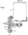
- FIG. 2 of the drawing shows the pump membrane 5 at top dead center connecting rod 4, i.e. at the end of the ejection stroke.
- the membrane 5 practically fills the entire pump chamber 7 (none Dead space).
- the hinge-like recesses 9 and 10 are in this Position "compressed” so that the outer areas of the Membrane are elastically biased. Thanks to this bias the movement of the connecting rod 4 back to bottom dead center is supported (Energy saving).
Landscapes
- Engineering & Computer Science (AREA)
- Mechanical Engineering (AREA)
- General Engineering & Computer Science (AREA)
- Reciprocating Pumps (AREA)
Abstract
Description
- Fig. 1
- eine erfindungsgemässe Membranpumpe im Schnitt, mit der Membran im unteren Totpunkt, d.h. am Ende des Ansaughubes, und
- Fig. 2
- eine entsprechende Darstellung mit dem Pleuel und der Membrane im oberen Totpunkt, d.h. am Ende des Ausstosshubes.
Claims (5)
- Membranpumpe als Saugpumpe, insbesondere zur Erzeugung eines Vakuums, mit einer über einen Kurbeltrieb mittels Pleuel motorisch angetriebenen elastischen Pumpenmembran, welche einen in einer Grundplatte vorgesehenen Pumpenraum überspannt, dadurch gekennzeichnet, dass die in der Grundplatte vorgesehene Wand des Pumpenraumes von einem zentralen ebenen Bodenabschnitt aus sich konisch erweiternd zum Seitenrand hin verläuft und die den Pumpenraum überspannende Membran derart ausgebildet und angeordnet ist, dass sie sich im oberen Totpunkt (OTP) des Pleuels an die gesamte Pumpenraumwand und deren Seitenrand im wesentlichen dicht anlegt, so dass im OTP des Pleuels praktisch kein Totraum verbleibt, wobei die Membran aus im wesentlichen eigensteifem elastischem Material vorbestimmter Dicke und Konfiguration besteht und deren Verformung unter gleichzeitiger Vorspannung zwecks Anpassung an die Pumpenraumwand und den Seitenrand des Pumpenraumes beim Pleuelhub in Richtung des OTP durch mindestens eine kreisförmig verlaufende Vertiefung in der Rückwand der Membran gewährleistet ist, welche Vertiefung ein elastisch vorspannbares Scharnier bildet.
- Membranpumpe nach Anspruch 1, dadurch gekennzeichnet, dass die kreisförmige Vertiefung in der Membranrückwand etwa im Bereich über dem Uebergang des ebenen Bodenabschnittes des Pumpenraums und des sich konisch erweiternden Wandabschnittes liegt.
- Membranpumpe nach Anspruch 1 oder 2, dadurch gekennzeichnet, dass eine weitere kreisförmig verlaufende Vertiefung in der Rückwand der Membran vorgesehen ist, welche konzentrisch zur ersten Vertiefung im Bereich über dem Seitenrand des Pumpenraums verläuft.
- Membranpumpe nach einem der Ansprüche 1 bis 3, dadurch gekennzeichnet, dass im Bodenabschnitt des Pumpenraumes Einlassund Auslassventile vorgesehen sind, wobei die Ventile auf der Rückseite der im Bereich des genannten Bodenabschnittes dünnwandigen Grundplatte angeordnet sind, so dass minimale Toträume zwischen Ventilen und dem Pumpenraum verbleiben.
- Membranpumpe nach einem der Ansprüche 1 bis 4, dadurch gekennzeichnet, dass die Membran aus Silikon besteht und z.B. eine Härte von ca. 80 Shore aufweist.
Priority Applications (12)
| Application Number | Priority Date | Filing Date | Title |
|---|---|---|---|
| AT01100206T ATE368181T1 (de) | 2001-01-02 | 2001-01-02 | Membranpumpe |
| EP01100206A EP1219833B1 (de) | 2001-01-02 | 2001-01-02 | Membranpumpe |
| ES01100206T ES2288887T3 (es) | 2001-01-02 | 2001-01-02 | Bomba de membrana. |
| DE50112760T DE50112760D1 (de) | 2001-01-02 | 2001-01-02 | Membranpumpe |
| PCT/CH2001/000733 WO2002053914A1 (de) | 2001-01-02 | 2001-12-20 | Membranpumpe |
| AU2002220442A AU2002220442B2 (en) | 2001-01-02 | 2001-12-20 | Diaphragm pump |
| JP2002554395A JP3993103B2 (ja) | 2001-01-02 | 2001-12-20 | ダイアフラムポンプ |
| US10/250,470 US7070400B2 (en) | 2001-01-02 | 2001-12-20 | Diaphragm pump with eliminated pump chamber dead space, and circular recesses on the reverse side of the diaphragm for improved diaphragm chamber wall adherence |
| CA2433093A CA2433093C (en) | 2001-01-02 | 2001-12-20 | Diaphragm pump |
| KR1020037008816A KR100852450B1 (ko) | 2001-01-02 | 2001-12-20 | 다이어프램 펌프 |
| HK02109369.2A HK1049362B (zh) | 2001-01-02 | 2002-12-27 | 隔膜泵 |
| NO20033019A NO20033019L (no) | 2001-01-02 | 2003-07-01 | Membranpumpe |
Applications Claiming Priority (1)
| Application Number | Priority Date | Filing Date | Title |
|---|---|---|---|
| EP01100206A EP1219833B1 (de) | 2001-01-02 | 2001-01-02 | Membranpumpe |
Publications (2)
| Publication Number | Publication Date |
|---|---|
| EP1219833A1 true EP1219833A1 (de) | 2002-07-03 |
| EP1219833B1 EP1219833B1 (de) | 2007-07-25 |
Family
ID=8176137
Family Applications (1)
| Application Number | Title | Priority Date | Filing Date |
|---|---|---|---|
| EP01100206A Expired - Lifetime EP1219833B1 (de) | 2001-01-02 | 2001-01-02 | Membranpumpe |
Country Status (12)
| Country | Link |
|---|---|
| US (1) | US7070400B2 (de) |
| EP (1) | EP1219833B1 (de) |
| JP (1) | JP3993103B2 (de) |
| KR (1) | KR100852450B1 (de) |
| AT (1) | ATE368181T1 (de) |
| AU (1) | AU2002220442B2 (de) |
| CA (1) | CA2433093C (de) |
| DE (1) | DE50112760D1 (de) |
| ES (1) | ES2288887T3 (de) |
| HK (1) | HK1049362B (de) |
| NO (1) | NO20033019L (de) |
| WO (1) | WO2002053914A1 (de) |
Cited By (3)
| Publication number | Priority date | Publication date | Assignee | Title |
|---|---|---|---|---|
| DE10312899A1 (de) * | 2003-03-22 | 2004-10-07 | Knf Neuberger Gmbh | Membranpumpe |
| WO2017029178A3 (de) * | 2015-08-20 | 2017-04-06 | Medmix Systems Ag | Membranpumpe mit medientrennung |
| US9956331B2 (en) | 2009-09-22 | 2018-05-01 | Medela Holding Ag | Device and method for expressing human breast milk |
Families Citing this family (23)
| Publication number | Priority date | Publication date | Assignee | Title |
|---|---|---|---|---|
| JP4587098B2 (ja) * | 2004-07-21 | 2010-11-24 | Smc株式会社 | ポンプ装置 |
| US8292598B2 (en) * | 2004-11-23 | 2012-10-23 | Entegris, Inc. | System and method for a variable home position dispense system |
| KR101243509B1 (ko) | 2005-12-02 | 2013-03-20 | 엔테그리스, 아이엔씨. | 펌프에서의 압력 보상을 위한 시스템 및 방법 |
| US7686595B1 (en) * | 2005-12-12 | 2010-03-30 | Stephen Graham | Diaphragm pump |
| TWI402423B (zh) | 2006-02-28 | 2013-07-21 | Entegris Inc | 用於一幫浦操作之系統及方法 |
| CN101636585B (zh) * | 2007-03-13 | 2012-02-22 | 美德乐控股公司 | 隔膜真空泵单元 |
| JP2009062870A (ja) * | 2007-09-06 | 2009-03-26 | I & T:Kk | エアーポンプ |
| ES2776709T3 (es) | 2007-11-21 | 2020-07-31 | Smith & Nephew | Apósito para heridas |
| GB0723855D0 (en) | 2007-12-06 | 2008-01-16 | Smith & Nephew | Apparatus and method for wound volume measurement |
| US20090246035A1 (en) * | 2008-03-28 | 2009-10-01 | Smiths Medical Asd, Inc. | Pump Module Fluidically Isolated Displacement Device |
| US20100158715A1 (en) * | 2008-12-24 | 2010-06-24 | Min-Hsieng Wang | Mute compressor |
| WO2010151291A1 (en) * | 2009-06-22 | 2010-12-29 | Lansinoh Laboratories, Inc. | Breast pump |
| GB0912229D0 (en) | 2009-07-14 | 2009-08-26 | Jackel Int Ltd | A breast pump |
| CH702436A1 (fr) * | 2009-12-23 | 2011-06-30 | Jean-Denis Rochat | Pompe doseuse a usage medical. |
| GB201015656D0 (en) | 2010-09-20 | 2010-10-27 | Smith & Nephew | Pressure control apparatus |
| US9067003B2 (en) | 2011-05-26 | 2015-06-30 | Kalypto Medical, Inc. | Method for providing negative pressure to a negative pressure wound therapy bandage |
| US9084845B2 (en) | 2011-11-02 | 2015-07-21 | Smith & Nephew Plc | Reduced pressure therapy apparatuses and methods of using same |
| US9901664B2 (en) | 2012-03-20 | 2018-02-27 | Smith & Nephew Plc | Controlling operation of a reduced pressure therapy system based on dynamic duty cycle threshold determination |
| US9427505B2 (en) | 2012-05-15 | 2016-08-30 | Smith & Nephew Plc | Negative pressure wound therapy apparatus |
| CN105142767B (zh) * | 2013-03-14 | 2017-12-12 | 艺康美国股份有限公司 | 聚合物溶解系统 |
| KR101616964B1 (ko) | 2014-06-16 | 2016-05-11 | 강소대 | 크랭크축을 이용한 압축공기발생기 |
| AU2015370583B2 (en) | 2014-12-22 | 2020-08-20 | Smith & Nephew Plc | Negative pressure wound therapy apparatus and methods |
| DE102020126241B4 (de) * | 2020-10-07 | 2026-03-19 | Alfmeier Präzision SE | Membrananordnung mit um den Membrankörper umlaufendem Ring sowie Sitzanordnung und Pumpenanordnung |
Citations (6)
| Publication number | Priority date | Publication date | Assignee | Title |
|---|---|---|---|---|
| US4231287A (en) * | 1978-05-01 | 1980-11-04 | Physics International Company | Spring diaphragm |
| DE4026670A1 (de) * | 1990-08-23 | 1992-03-05 | Alcatel Hochvakuumtechnik Gmbh | Mechanische vakuumpumpe |
| DE9410116U1 (de) * | 1994-06-23 | 1994-08-11 | Knf-Neuberger Gmbh, 79112 Freiburg | Membranpumpe mit einer Formmembran |
| DE29514009U1 (de) * | 1995-08-31 | 1995-11-09 | Hyco-Vakuumtechnik GmbH, 81247 München | Vakuumpumpe |
| US5699717A (en) * | 1995-03-24 | 1997-12-23 | Knf Neuberger Gmbh | Diaphragm pump with shaped diaphragm having radially and circumferentially extending ribs |
| US5776098A (en) * | 1995-08-03 | 1998-07-07 | Medela, Incorporated | Diaphragm pump and pump mounted in a carrying case useful in breast pumping |
Family Cites Families (12)
| Publication number | Priority date | Publication date | Assignee | Title |
|---|---|---|---|---|
| US3776666A (en) * | 1972-02-18 | 1973-12-04 | Deknatel Inc | Portable pump |
| US4086036A (en) * | 1976-05-17 | 1978-04-25 | Cole-Parmer Instrument Company | Diaphragm pump |
| US4571160A (en) * | 1984-07-24 | 1986-02-18 | The Mead Corporation | Diaphragm pump having a flat plate actuating member slidable in slots |
| CH667701A5 (de) * | 1985-11-05 | 1988-10-31 | Hans Meyer | Pumpe. |
| IL83259A (en) | 1987-07-20 | 1992-05-25 | D F Lab Ltd | Disposable cell and diaphragm pump for use of same |
| DE3838141C2 (de) * | 1988-11-10 | 1998-12-24 | Knf Neuberger Gmbh | Membranpumpe |
| DE4007932A1 (de) * | 1990-03-13 | 1991-09-19 | Knf Neuberger Gmbh | Membranpumpe mit einer formmembrane |
| JPH03279684A (ja) * | 1990-03-29 | 1991-12-10 | Aisin Seiki Co Ltd | 圧縮装置 |
| DE4200838C2 (de) * | 1992-01-15 | 1994-12-22 | Knf Neuberger Gmbh | Pumpe mit vom Fördermedium gesteuerten Ventilen |
| DE4328559C5 (de) * | 1993-08-25 | 2004-11-25 | Knf-Neuberger Gmbh | Membranpumpe mit wenigstens zwei Membranen |
| DE19601839C2 (de) * | 1996-01-19 | 1999-12-02 | Knf Neuberger Gmbh | Membranpumpe |
| US5676531A (en) * | 1996-03-21 | 1997-10-14 | Pulsafeeder, Inc. | Autoclavable pump head assembly |
-
2001
- 2001-01-02 AT AT01100206T patent/ATE368181T1/de active
- 2001-01-02 ES ES01100206T patent/ES2288887T3/es not_active Expired - Lifetime
- 2001-01-02 EP EP01100206A patent/EP1219833B1/de not_active Expired - Lifetime
- 2001-01-02 DE DE50112760T patent/DE50112760D1/de not_active Expired - Lifetime
- 2001-12-20 CA CA2433093A patent/CA2433093C/en not_active Expired - Fee Related
- 2001-12-20 AU AU2002220442A patent/AU2002220442B2/en not_active Ceased
- 2001-12-20 JP JP2002554395A patent/JP3993103B2/ja not_active Expired - Fee Related
- 2001-12-20 WO PCT/CH2001/000733 patent/WO2002053914A1/de not_active Ceased
- 2001-12-20 US US10/250,470 patent/US7070400B2/en not_active Expired - Lifetime
- 2001-12-20 KR KR1020037008816A patent/KR100852450B1/ko not_active Expired - Fee Related
-
2002
- 2002-12-27 HK HK02109369.2A patent/HK1049362B/zh not_active IP Right Cessation
-
2003
- 2003-07-01 NO NO20033019A patent/NO20033019L/no not_active Application Discontinuation
Patent Citations (6)
| Publication number | Priority date | Publication date | Assignee | Title |
|---|---|---|---|---|
| US4231287A (en) * | 1978-05-01 | 1980-11-04 | Physics International Company | Spring diaphragm |
| DE4026670A1 (de) * | 1990-08-23 | 1992-03-05 | Alcatel Hochvakuumtechnik Gmbh | Mechanische vakuumpumpe |
| DE9410116U1 (de) * | 1994-06-23 | 1994-08-11 | Knf-Neuberger Gmbh, 79112 Freiburg | Membranpumpe mit einer Formmembran |
| US5699717A (en) * | 1995-03-24 | 1997-12-23 | Knf Neuberger Gmbh | Diaphragm pump with shaped diaphragm having radially and circumferentially extending ribs |
| US5776098A (en) * | 1995-08-03 | 1998-07-07 | Medela, Incorporated | Diaphragm pump and pump mounted in a carrying case useful in breast pumping |
| DE29514009U1 (de) * | 1995-08-31 | 1995-11-09 | Hyco-Vakuumtechnik GmbH, 81247 München | Vakuumpumpe |
Cited By (8)
| Publication number | Priority date | Publication date | Assignee | Title |
|---|---|---|---|---|
| DE10312899A1 (de) * | 2003-03-22 | 2004-10-07 | Knf Neuberger Gmbh | Membranpumpe |
| US7363850B2 (en) | 2003-03-22 | 2008-04-29 | Knf Neuberger Gmbh | Diaphragm pump |
| US9956331B2 (en) | 2009-09-22 | 2018-05-01 | Medela Holding Ag | Device and method for expressing human breast milk |
| EP2480264B1 (de) * | 2009-09-22 | 2018-09-05 | Medela Holding AG | Vorrichtung und verfahren zum abpumpen von menschlicher muttermilch |
| US10493188B2 (en) | 2009-09-22 | 2019-12-03 | Medela Holding Ag | Highly efficient breastpump and system for expressing breastmilk |
| US10493187B2 (en) | 2009-09-22 | 2019-12-03 | Medela Holding Ag | Highly efficient breastpump and system for expressing breastmilk |
| US10639407B2 (en) | 2009-09-22 | 2020-05-05 | Medela Holding Ag | Device and method for expressing human breast milk |
| WO2017029178A3 (de) * | 2015-08-20 | 2017-04-06 | Medmix Systems Ag | Membranpumpe mit medientrennung |
Also Published As
| Publication number | Publication date |
|---|---|
| JP3993103B2 (ja) | 2007-10-17 |
| EP1219833B1 (de) | 2007-07-25 |
| WO2002053914A1 (de) | 2002-07-11 |
| CA2433093A1 (en) | 2002-07-11 |
| NO20033019D0 (no) | 2003-07-01 |
| CA2433093C (en) | 2010-05-11 |
| KR20030065582A (ko) | 2003-08-06 |
| HK1049362B (zh) | 2008-03-14 |
| AU2002220442B2 (en) | 2005-09-01 |
| DE50112760D1 (de) | 2007-09-06 |
| HK1049362A1 (zh) | 2003-05-09 |
| KR100852450B1 (ko) | 2008-08-14 |
| JP2004522890A (ja) | 2004-07-29 |
| NO20033019L (no) | 2003-08-21 |
| US7070400B2 (en) | 2006-07-04 |
| ATE368181T1 (de) | 2007-08-15 |
| ES2288887T3 (es) | 2008-02-01 |
| US20040071572A1 (en) | 2004-04-15 |
Similar Documents
| Publication | Publication Date | Title |
|---|---|---|
| EP1219833A1 (de) | Membranpumpe | |
| DE4007932C2 (de) | ||
| DE10247293B4 (de) | Pumpe, welche mit Zwischenwänden versehen ist | |
| DE1628144C3 (de) | Saugdrosselsteuereinrichtung | |
| DE102007005736A1 (de) | Verdrängungs-Pumpe zur Förderung eines Fluids mit automatischer Anpassung an die Kompressibilität dieses Fluids | |
| EP1671031A2 (de) | Fluidpumpe, insbesondere kraftstoffhochdruckpumpe, mit druckdämpfer | |
| DE3018687A1 (de) | Membran fuer hochdruckfoerderpumpen, kompressoren o.dgl. | |
| DE112004001593B4 (de) | Wasserstrahleinrichtung zum Trennen einer biologischen Struktur | |
| EP2725226A1 (de) | Kolbenpumpe | |
| DE3934124A1 (de) | Druckluftgetriebene pumpenanordnung | |
| DE102006000099B4 (de) | Membranpumpe | |
| DE102006000010B4 (de) | Hochdruckpumpe mit verkleinertem Aufbau | |
| WO2004040128A1 (de) | Kraftstoffhochdruckpumpe mit kugelventil im niederdruck-einlass | |
| DE10222846B4 (de) | Vorrichtung zur Fluidverdichtung | |
| DE202020107139U1 (de) | Membranpumpe | |
| EP1306553A2 (de) | Kraftstoffpumpe, Kraftstoffsystem, Verfahren zum Betreiben eines Kraftstoffsystems sowie Brennkraftmaschine | |
| DE102007010729B3 (de) | Vakuumpumpe | |
| DE102006028986A1 (de) | Konträrmembranantrieb zur Effizienzsteigerung von Mikropumpen | |
| DE102007060026A1 (de) | Membranpumpe und Vorrichtung mit einer solchen | |
| DE19506184A1 (de) | Reziprozierender Kolbenmotor, funktionierend mit Druckmedium | |
| DE102010001369B4 (de) | Peristaltisches System, Fluidfördervorrichtung, Pipettiervorrichtung, Manschette und Verfahren zum Betrieb des peristaltischen Systems | |
| EP1574261B1 (de) | Pulverförderpumpe | |
| WO2001040654A1 (de) | Pneumatisches bauelement für ein schaltlager | |
| EP0379697B1 (de) | Hydrostatischer Antrieb | |
| EP1375919B1 (de) | Kompressor, insbesondere für ein Kraftfahrzeug-Luftfedersystem |
Legal Events
| Date | Code | Title | Description |
|---|---|---|---|
| PUAI | Public reference made under article 153(3) epc to a published international application that has entered the european phase |
Free format text: ORIGINAL CODE: 0009012 |
|
| AK | Designated contracting states |
Kind code of ref document: A1 Designated state(s): AT BE CH CY DE DK ES FI FR GB GR IE IT LI LU MC NL PT SE TR |
|
| AX | Request for extension of the european patent |
Free format text: AL;LT;LV;MK;RO;SI |
|
| 17P | Request for examination filed |
Effective date: 20021221 |
|
| AKX | Designation fees paid |
Designated state(s): AT BE CH CY DE DK ES FI FR GB GR IE IT LI LU MC NL PT SE TR |
|
| GRAP | Despatch of communication of intention to grant a patent |
Free format text: ORIGINAL CODE: EPIDOSNIGR1 |
|
| RAP1 | Party data changed (applicant data changed or rights of an application transferred) |
Owner name: MEDELA HOLDING AG |
|
| GRAS | Grant fee paid |
Free format text: ORIGINAL CODE: EPIDOSNIGR3 |
|
| GRAA | (expected) grant |
Free format text: ORIGINAL CODE: 0009210 |
|
| AK | Designated contracting states |
Kind code of ref document: B1 Designated state(s): AT BE CH CY DE DK ES FI FR GB GR IE IT LI LU MC NL PT SE TR |
|
| REG | Reference to a national code |
Ref country code: GB Ref legal event code: FG4D Free format text: NOT ENGLISH |
|
| REG | Reference to a national code |
Ref country code: CH Ref legal event code: EP |
|
| REG | Reference to a national code |
Ref country code: CH Ref legal event code: NV Representative=s name: ISLER & PEDRAZZINI AG |
|
| REG | Reference to a national code |
Ref country code: IE Ref legal event code: FG4D Free format text: LANGUAGE OF EP DOCUMENT: GERMAN |
|
| REF | Corresponds to: |
Ref document number: 50112760 Country of ref document: DE Date of ref document: 20070906 Kind code of ref document: P |
|
| REG | Reference to a national code |
Ref country code: CH Ref legal event code: PCAR Free format text: ISLER & PEDRAZZINI AG;POSTFACH 1772;8027 ZUERICH (CH) |
|
| REG | Reference to a national code |
Ref country code: SE Ref legal event code: TRGR |
|
| GBT | Gb: translation of ep patent filed (gb section 77(6)(a)/1977) |
Effective date: 20070919 |
|
| ET | Fr: translation filed | ||
| PG25 | Lapsed in a contracting state [announced via postgrant information from national office to epo] |
Ref country code: PT Free format text: LAPSE BECAUSE OF FAILURE TO SUBMIT A TRANSLATION OF THE DESCRIPTION OR TO PAY THE FEE WITHIN THE PRESCRIBED TIME-LIMIT Effective date: 20071226 |
|
| REG | Reference to a national code |
Ref country code: ES Ref legal event code: FG2A Ref document number: 2288887 Country of ref document: ES Kind code of ref document: T3 |
|
| REG | Reference to a national code |
Ref country code: IE Ref legal event code: FD4D |
|
| REG | Reference to a national code |
Ref country code: HK Ref legal event code: GR Ref document number: 1049362 Country of ref document: HK |
|
| PG25 | Lapsed in a contracting state [announced via postgrant information from national office to epo] |
Ref country code: DK Free format text: LAPSE BECAUSE OF FAILURE TO SUBMIT A TRANSLATION OF THE DESCRIPTION OR TO PAY THE FEE WITHIN THE PRESCRIBED TIME-LIMIT Effective date: 20070725 Ref country code: GR Free format text: LAPSE BECAUSE OF FAILURE TO SUBMIT A TRANSLATION OF THE DESCRIPTION OR TO PAY THE FEE WITHIN THE PRESCRIBED TIME-LIMIT Effective date: 20071026 |
|
| PG25 | Lapsed in a contracting state [announced via postgrant information from national office to epo] |
Ref country code: IE Free format text: LAPSE BECAUSE OF FAILURE TO SUBMIT A TRANSLATION OF THE DESCRIPTION OR TO PAY THE FEE WITHIN THE PRESCRIBED TIME-LIMIT Effective date: 20070725 |
|
| PLBE | No opposition filed within time limit |
Free format text: ORIGINAL CODE: 0009261 |
|
| STAA | Information on the status of an ep patent application or granted ep patent |
Free format text: STATUS: NO OPPOSITION FILED WITHIN TIME LIMIT |
|
| 26N | No opposition filed |
Effective date: 20080428 |
|
| PG25 | Lapsed in a contracting state [announced via postgrant information from national office to epo] |
Ref country code: MC Free format text: LAPSE BECAUSE OF NON-PAYMENT OF DUE FEES Effective date: 20080131 |
|
| PG25 | Lapsed in a contracting state [announced via postgrant information from national office to epo] |
Ref country code: CY Free format text: LAPSE BECAUSE OF FAILURE TO SUBMIT A TRANSLATION OF THE DESCRIPTION OR TO PAY THE FEE WITHIN THE PRESCRIBED TIME-LIMIT Effective date: 20070725 |
|
| PG25 | Lapsed in a contracting state [announced via postgrant information from national office to epo] |
Ref country code: LU Free format text: LAPSE BECAUSE OF NON-PAYMENT OF DUE FEES Effective date: 20080102 |
|
| PGFP | Annual fee paid to national office [announced via postgrant information from national office to epo] |
Ref country code: FI Payment date: 20110113 Year of fee payment: 11 Ref country code: SE Payment date: 20110113 Year of fee payment: 11 Ref country code: AT Payment date: 20110113 Year of fee payment: 11 |
|
| PGFP | Annual fee paid to national office [announced via postgrant information from national office to epo] |
Ref country code: BE Payment date: 20110104 Year of fee payment: 11 |
|
| PGFP | Annual fee paid to national office [announced via postgrant information from national office to epo] |
Ref country code: ES Payment date: 20110125 Year of fee payment: 11 |
|
| BERE | Be: lapsed |
Owner name: MEDELA HOLDING A.G. Effective date: 20120131 |
|
| REG | Reference to a national code |
Ref country code: SE Ref legal event code: EUG |
|
| PG25 | Lapsed in a contracting state [announced via postgrant information from national office to epo] |
Ref country code: FI Free format text: LAPSE BECAUSE OF NON-PAYMENT OF DUE FEES Effective date: 20120102 Ref country code: SE Free format text: LAPSE BECAUSE OF NON-PAYMENT OF DUE FEES Effective date: 20120103 |
|
| REG | Reference to a national code |
Ref country code: AT Ref legal event code: MM01 Ref document number: 368181 Country of ref document: AT Kind code of ref document: T Effective date: 20120102 |
|
| PG25 | Lapsed in a contracting state [announced via postgrant information from national office to epo] |
Ref country code: BE Free format text: LAPSE BECAUSE OF NON-PAYMENT OF DUE FEES Effective date: 20120131 |
|
| PG25 | Lapsed in a contracting state [announced via postgrant information from national office to epo] |
Ref country code: AT Free format text: LAPSE BECAUSE OF NON-PAYMENT OF DUE FEES Effective date: 20120102 |
|
| REG | Reference to a national code |
Ref country code: ES Ref legal event code: FD2A Effective date: 20130708 |
|
| PG25 | Lapsed in a contracting state [announced via postgrant information from national office to epo] |
Ref country code: ES Free format text: LAPSE BECAUSE OF NON-PAYMENT OF DUE FEES Effective date: 20120103 |
|
| REG | Reference to a national code |
Ref country code: FR Ref legal event code: PLFP Year of fee payment: 15 |
|
| REG | Reference to a national code |
Ref country code: FR Ref legal event code: PLFP Year of fee payment: 16 |
|
| REG | Reference to a national code |
Ref country code: FR Ref legal event code: PLFP Year of fee payment: 17 |
|
| REG | Reference to a national code |
Ref country code: FR Ref legal event code: PLFP Year of fee payment: 18 |
|
| PGFP | Annual fee paid to national office [announced via postgrant information from national office to epo] |
Ref country code: TR Payment date: 20180102 Year of fee payment: 18 Ref country code: IT Payment date: 20180129 Year of fee payment: 18 |
|
| PGFP | Annual fee paid to national office [announced via postgrant information from national office to epo] |
Ref country code: NL Payment date: 20190121 Year of fee payment: 19 Ref country code: DE Payment date: 20190123 Year of fee payment: 19 Ref country code: CH Payment date: 20190111 Year of fee payment: 19 Ref country code: GB Payment date: 20190121 Year of fee payment: 19 Ref country code: FR Payment date: 20190123 Year of fee payment: 19 |
|
| PG25 | Lapsed in a contracting state [announced via postgrant information from national office to epo] |
Ref country code: IT Free format text: LAPSE BECAUSE OF NON-PAYMENT OF DUE FEES Effective date: 20190102 |
|
| REG | Reference to a national code |
Ref country code: DE Ref legal event code: R119 Ref document number: 50112760 Country of ref document: DE |
|
| REG | Reference to a national code |
Ref country code: CH Ref legal event code: PL |
|
| REG | Reference to a national code |
Ref country code: NL Ref legal event code: MM Effective date: 20200201 |
|
| GBPC | Gb: european patent ceased through non-payment of renewal fee |
Effective date: 20200102 |
|
| PG25 | Lapsed in a contracting state [announced via postgrant information from national office to epo] |
Ref country code: NL Free format text: LAPSE BECAUSE OF NON-PAYMENT OF DUE FEES Effective date: 20200201 Ref country code: GB Free format text: LAPSE BECAUSE OF NON-PAYMENT OF DUE FEES Effective date: 20200102 Ref country code: FR Free format text: LAPSE BECAUSE OF NON-PAYMENT OF DUE FEES Effective date: 20200131 Ref country code: DE Free format text: LAPSE BECAUSE OF NON-PAYMENT OF DUE FEES Effective date: 20200801 |
|
| PG25 | Lapsed in a contracting state [announced via postgrant information from national office to epo] |
Ref country code: LI Free format text: LAPSE BECAUSE OF NON-PAYMENT OF DUE FEES Effective date: 20200131 Ref country code: CH Free format text: LAPSE BECAUSE OF NON-PAYMENT OF DUE FEES Effective date: 20200131 |
|
| PG25 | Lapsed in a contracting state [announced via postgrant information from national office to epo] |
Ref country code: TR Free format text: LAPSE BECAUSE OF NON-PAYMENT OF DUE FEES Effective date: 20200102 |