EP1217693A2 - Anschlussleiste - Google Patents
Anschlussleiste Download PDFInfo
- Publication number
- EP1217693A2 EP1217693A2 EP01129776A EP01129776A EP1217693A2 EP 1217693 A2 EP1217693 A2 EP 1217693A2 EP 01129776 A EP01129776 A EP 01129776A EP 01129776 A EP01129776 A EP 01129776A EP 1217693 A2 EP1217693 A2 EP 1217693A2
- Authority
- EP
- European Patent Office
- Prior art keywords
- carrier strip
- module
- housing
- terminal block
- leg
- Prior art date
- Legal status (The legal status is an assumption and is not a legal conclusion. Google has not performed a legal analysis and makes no representation as to the accuracy of the status listed.)
- Granted
Links
Images

Classifications
-
- H—ELECTRICITY
- H01—ELECTRIC ELEMENTS
- H01R—ELECTRICALLY-CONDUCTIVE CONNECTIONS; STRUCTURAL ASSOCIATIONS OF A PLURALITY OF MUTUALLY-INSULATED ELECTRICAL CONNECTING ELEMENTS; COUPLING DEVICES; CURRENT COLLECTORS
- H01R4/00—Electrically-conductive connections between two or more conductive members in direct contact, i.e. touching one another; Means for effecting or maintaining such contact; Electrically-conductive connections having two or more spaced connecting locations for conductors and using contact members penetrating insulation
- H01R4/28—Clamped connections, spring connections
- H01R4/48—Clamped connections, spring connections utilising a spring, clip, or other resilient member
- H01R4/4809—Clamped connections, spring connections utilising a spring, clip, or other resilient member using a leaf spring to bias the conductor toward the busbar
- H01R4/484—Spring housing details
-
- H—ELECTRICITY
- H01—ELECTRIC ELEMENTS
- H01R—ELECTRICALLY-CONDUCTIVE CONNECTIONS; STRUCTURAL ASSOCIATIONS OF A PLURALITY OF MUTUALLY-INSULATED ELECTRICAL CONNECTING ELEMENTS; COUPLING DEVICES; CURRENT COLLECTORS
- H01R4/00—Electrically-conductive connections between two or more conductive members in direct contact, i.e. touching one another; Means for effecting or maintaining such contact; Electrically-conductive connections having two or more spaced connecting locations for conductors and using contact members penetrating insulation
- H01R4/28—Clamped connections, spring connections
- H01R4/48—Clamped connections, spring connections utilising a spring, clip, or other resilient member
- H01R4/4809—Clamped connections, spring connections utilising a spring, clip, or other resilient member using a leaf spring to bias the conductor toward the busbar
- H01R4/4846—Busbar details
- H01R4/485—Single busbar common to multiple springs
-
- H—ELECTRICITY
- H01—ELECTRIC ELEMENTS
- H01R—ELECTRICALLY-CONDUCTIVE CONNECTIONS; STRUCTURAL ASSOCIATIONS OF A PLURALITY OF MUTUALLY-INSULATED ELECTRICAL CONNECTING ELEMENTS; COUPLING DEVICES; CURRENT COLLECTORS
- H01R4/00—Electrically-conductive connections between two or more conductive members in direct contact, i.e. touching one another; Means for effecting or maintaining such contact; Electrically-conductive connections having two or more spaced connecting locations for conductors and using contact members penetrating insulation
- H01R4/28—Clamped connections, spring connections
- H01R4/48—Clamped connections, spring connections utilising a spring, clip, or other resilient member
- H01R4/4809—Clamped connections, spring connections utilising a spring, clip, or other resilient member using a leaf spring to bias the conductor toward the busbar
- H01R4/48185—Clamped connections, spring connections utilising a spring, clip, or other resilient member using a leaf spring to bias the conductor toward the busbar adapted for axial insertion of a wire end
- H01R4/4819—Clamped connections, spring connections utilising a spring, clip, or other resilient member using a leaf spring to bias the conductor toward the busbar adapted for axial insertion of a wire end the spring shape allowing insertion of the conductor end when the spring is unbiased
- H01R4/4821—Single-blade spring
-
- H—ELECTRICITY
- H01—ELECTRIC ELEMENTS
- H01R—ELECTRICALLY-CONDUCTIVE CONNECTIONS; STRUCTURAL ASSOCIATIONS OF A PLURALITY OF MUTUALLY-INSULATED ELECTRICAL CONNECTING ELEMENTS; COUPLING DEVICES; CURRENT COLLECTORS
- H01R4/00—Electrically-conductive connections between two or more conductive members in direct contact, i.e. touching one another; Means for effecting or maintaining such contact; Electrically-conductive connections having two or more spaced connecting locations for conductors and using contact members penetrating insulation
- H01R4/28—Clamped connections, spring connections
- H01R4/48—Clamped connections, spring connections utilising a spring, clip, or other resilient member
- H01R4/4809—Clamped connections, spring connections utilising a spring, clip, or other resilient member using a leaf spring to bias the conductor toward the busbar
- H01R4/484—Spring housing details
- H01R4/4842—Spring housing details the spring housing being provided with a single opening for insertion of a spring-activating tool
-
- H—ELECTRICITY
- H01—ELECTRIC ELEMENTS
- H01R—ELECTRICALLY-CONDUCTIVE CONNECTIONS; STRUCTURAL ASSOCIATIONS OF A PLURALITY OF MUTUALLY-INSULATED ELECTRICAL CONNECTING ELEMENTS; COUPLING DEVICES; CURRENT COLLECTORS
- H01R9/00—Structural associations of a plurality of mutually-insulated electrical connecting elements, e.g. terminal strips or terminal blocks; Terminals or binding posts mounted upon a base or in a case; Bases therefor
- H01R9/22—Bases, e.g. strip, block, panel
- H01R9/24—Terminal blocks
Definitions
- the invention relates to a terminal block for electrical distributors, in particular for Connection of protective and neutral conductors (PE / N terminal), with one conductor rail and a large number of connection elements for connecting the conductor to be connected to the conductor rail, a support bar and attachable to the support bar in a row, at least one of the connecting element modules with an insulating housing and a conductor rail section arranged in the housing for the formation of the conductor rail, as well as with bridges for the electrical connection of the conductor rail sections on the Carrier strip of adjacent modules.
- PE / N terminal protective and neutral conductors
- connection strips composed of connection modules are in distribution boxes used where e.g. with their ends on the side walls of the distribution box in such a distance are attached from the floor so that cables or wires fed to the distribution box, e.g. first under the bar and then in a loop to connect to the bar the bar can be returned.
- the present invention relates to a further development of those described in the introduction Terminal strip through which the attachment of the modules to the carrier strip is made easier becomes.
- the housing and the carrier strip have devices for plugging on of the module on the support bar transversely to the longitudinal direction of the support bar.
- connection strip which is used to attach the modules to one, possibly already in the distribution box installed, carrier strip only requires a translatory plug movement, leaves assemble conveniently with little effort.
- the module is forming a solid Connection snaps into place on the carrier bar.
- the carrier strip expediently has an angle profile with a first profile leg and a for this purpose, preferably arranged at an angle of 90 °, second profile leg.
- the through the Angle profile leg formed corner forms a seat for the modules to be strung together, the module housing with side surfaces at an angle to one another against the profile legs is applied.
- the module is on the carrier bar in one direction can be plugged parallel to the first profile leg against the second profile leg.
- the devices for plugging the module onto the support bar can be connected to the Housing of the module connected hook element with a, preferably parallel to comprise a hook leg extending on one side of the housing.
- a hook leg extending on one side of the housing.
- Carrier strip preferably the first profile leg, for arrangement between the hook leg and the housing of the module.
- the hook element preferably overlaps the free end edge in the attached state of the first angle leg.
- Means for plugging the module onto the support bar can also one of the Housing of the module projecting nose for engaging in a recess on the support bar comprise, this recess is expedient in the second angle leg is formed. In the embodiment in which the module against the second angle leg strikes, this nose ensures that the module is attached to the second angle leg, if necessary in a plane perpendicular to the direction of insertion.
- a latch for is on the housing of the module formed the engagement in a recess in the first angle leg.
- the locking nose is opposite the hook leg and stands by one through incisions in the housing wall formed, elastically movable tongue.
- the support bar Devices for plugging and / or latching repeating at a grid spacing educated. Accordingly, different modules can be attached to the support bar that differ in length by the grid spacing or a multiple thereof.
- the reference numeral 1 denotes a support bar, which has an angular profile with a first angle leg 2 and a second angle leg 3.
- the Carrier strip is at its ends in one via snap-in connector devices 4 to fix the electrical distribution box.
- first angle leg On the first angle leg are at a grid spacing near the free end of the Legs formed through recesses 5, which engage in a locking lug can, as will be explained below.
- the continuous recesses 6 limit one long side of the first angle leg 2 and each protrude into one in the second Angle leg 3 formed recess 7 into it.
- the second angle leg 3 has a bevel 8, which in the embodiment shown is labeled with slot numbers.
- angle legs 2 and 3 are each connected to one another via an end plate 9.
- modules 10 are attached to the carrier strip 1, which, as will be explained below, are attached to the bar and snapped into place. 2, in addition to a module 10, two shorter modules 10 'are and a longer module 10 ′′ is attached to the carrier strip 1.
- the modules mentioned differ from each other by a multiple of the above mentioned grid length.
- the module has a plastic housing 11 formed in several parts from housing parts 12 and 13 on, in which a copper conductor rail section 14 enclosed and between the mated housing parts 12 and 13 is fixed.
- the conductor rail section 14 has 8 openings 15 in the exemplary embodiment shown for the introduction of a conductor 16 to be connected, each opening 15 having a Spring 17 for clamping the conductor 16 to the conductor rail section 14 is assigned.
- Each opening 15 is also a supply channel 18 for the conductor 16 and a plug-in channel 19 for the introduction of a tool 20 for releasing the conductor 16 from the clamp connection assigned.
- the module shown in FIGS. 3 and 4 has two feed channels 21 for the Supply of conductors with a particularly large cross-section that are connected to screw terminals Clamping screws 22 are connectable.
- Each screw terminal has a clamping cage 24, in the one connected to the conductor rail section 14, not visible in the figures Contact tongue engages.
- the clamping cages 24 are each through an opening in the housing 11 out of the housing.
- the substantially cuboid housing 11 has a projecting at two corners Nose 25 on.
- the hook leg 27 is spaced apart from one another by two in the longitudinal direction of the carrier strip 1 arranged webs 28 and 29 connected to the housing 11.
- the locking lug 30 is elastic on one formed by incisions in the housing wall movable tongue 31 arranged.
- the tongue 31 delimits a plug-in channel on one side 32, into which one leg of a connecting bridge 33 (Fig. 2) can be inserted, which for electrical Connection of the conductor rail sections 14 arranged on the support bar 1 adjacent Serves modules.
- the bridge leg engages in an opening 34, which in one with the tongue 23 of the conductor rail section 14 is formed.
- the module is positioned transversely to the carrier strip 1 in a plug-in direction placed parallel to the first angle leg 2 on the support bar 1, the hook element 26 engages over the free end edge of the first angle leg 2.
- the in the direction of insertion Carrier strip 1 beveled latching lug 30 comes against the free end edge of the angle leg 2 to the system so that the elastic tongue 31 bends.
- the projecting lugs 25 each enter one of the recesses 6 in the second angle leg 3 of the support bar 1.
- the nose 30 snaps into one of the recesses 5 on the first Angle leg 2 a.
- the in the direction of the second angle leg 3 from the housing 11 protruding clamping cages 24 each have 7 place in one of the recesses.
- the length of the recesses 6 is in the longitudinal direction the support bar 1 dimensioned so that a corresponding nose in this recess of an adjacent module can intervene.
Landscapes
- Connections Arranged To Contact A Plurality Of Conductors (AREA)
- Connector Housings Or Holding Contact Members (AREA)
Abstract
Description
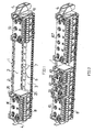
- Fig. 1
- eine Anschlussleiste nach der Erfindung mit einer Trägerleiste und darauf aufgesteckten Anschlussmodulen in einer ersten Bestückungsvariante,
- Fig. 2
- eine Anschlussleiste nach der Erfindung mit der Trägerleiste von Fig. 1 und darauf aufgesteckten Modulen in einer zweiten Bestückungsvariante,
- Fig. 3
- einen mit der Anschlussleiste von Fig. 1 und 2 verwendbaren Modul in einer Schnittansicht, und
- Fig. 4
- den Modul von Fig. 3 in einer perspektivischen Ansicht.
Claims (12)
- Anschlussleiste für elektrische Verteiler, insbesondere für den Anschluß von Schutz- und Nulleitern (PE/N-Klemme), mit einer Leiterschiene und einer Vielzahl von Anschlusselementen für die Verbindung anzuschließender Leiter (16) mit der Leiterschiene, einer Trägerleiste (1) und an der Trägerleiste unter Aneinanderreihung anbringbaren, wenigstens eines der Anschlusselemente aufweisenden Modulen (10) mit einem isolierenden Gehäuse (11) und einem in dem Gehäuse angeordneten Leiterschienenabschnitt (14) für die Bildung der Leiterschiene, sowie mit Brücken (33) zur elektrischen Verbindung der Leiterschienenabschnitte (14) an der Trägerleiste (1) benachbart angebrachter Module (10),
dadurch gekennzeichnet, dass das Gehäuse (11) und die Trägerleiste (1) Einrichtungen (5,6,25,26) zum Aufstecken des Moduls (10) auf die Trägerleiste (1) quer zur Längsrichtung der Trägerleiste (1) aufweisen. - Anschlussleiste nach Anspruch 1,
dadurch gekennzeichnet, dass der Modul (10) an der Trägerleiste (1) einrastbar ist. - Anschlussleiste nach Anspruch 1 oder 2,
dadurch gekennzeichnet, dass die Trägerleiste (1) ein Winkelprofil mit einem ersten Profilschenkel (2) und einem, dazu vorzugsweise im Winkel von 90° angeordneten, zweiten Profilschenkel (3) aufweist. - Anschlussleiste nach Anspruch 3,
dadurch gekennzeichnet, dass der Modul (10) auf die Trägerleiste (1) entlang dem ersten Profilschenkel (2) unter Anschlag gegen den zweiten Profilschenkel (3) aufsteckbar ist. - Anschlussleiste nach einem der Ansprüche 1 bis 4,
dadurch gekennzeichnet, dass die Einrichtungen (5,6,25,26) zum Aufstecken des Moduls (10) auf die Trägerleiste (1) ein mit dem Gehäuse (11) des Moduls (10) verbundenes Hakenelement (26) mit einem, sich vorzugsweise parallel zu einer Gehäuseseite erstreckenden, Hakenschenkel (27) umfassen. - Anschlussleiste nach Anspruch 5,
dadurch gekennzeichnet, dass das Hakenelement (26) den freien Endrand des ersten Winkelschenkels (2) übergreift. - Anschlussleiste nach Anspruch 5 oder 6,
dadurch gekennzeichnet, dass das Hakenelement (26) mit dem Gehäuse (11) des Moduls (10) über zwei, in Längsrichtung der Trägerleiste (1) zueinander im Abstand angeordnete, Stege (28,29) verbunden ist. - Anschlussleiste nach einem der Ansprüche 1 bis 7,
dadurch gekennzeichnet, dass die Einrichtungen (5,6,25,26) zum Aufstecken des Moduls (10) auf die Trägerleiste (1) eine von dem Gehäuse (11) des Moduls (10) vorspringende Nase (25) für den Eingriff in eine Ausnehmung (6) an der Trägerleiste (1) umfassen. - Anschlussleiste nach Anspruch 8,
dadurch gekennzeichnet, dass die Ausnehmung (6) in dem zweiten Winkelschenkel (3), vorzugsweise angrenzend an den ersten Winkelschenkel (2), gebildet ist. - Anschlussleiste nach einem der Ansprüche 1 bis 9,
dadurch gekennzeichnet, dass an dem Gehäuse (11) des Moduls (10) eine Rastnase (30) für den Eingriff in eine Rastausnehmung (5) in dem ersten Winkelschenkel (2) gebildet ist. - Anschlussleiste nach Anspruch 10,
dadurch gekennzeichnet, dass die Rastnase (30) gegenüberliegend zu dem Hakenschenkel (27) angeordnet ist. - Anschlussleiste nach einem der Ansprüche 1 bis 11,
dadurch gekennzeichnet, dass an der Trägerleiste (1) sich in einem Rasterabstand wiederholend Einrichtungen zum Aufstecken und/oder Einrasten gebildet sind.
Applications Claiming Priority (4)
| Application Number | Priority Date | Filing Date | Title |
|---|---|---|---|
| DE10063455 | 2000-12-20 | ||
| DE10063455 | 2000-12-20 | ||
| DE10103145 | 2001-01-24 | ||
| DE10103145A DE10103145C1 (de) | 2000-12-20 | 2001-01-24 | Anschlußleiste |
Publications (3)
| Publication Number | Publication Date |
|---|---|
| EP1217693A2 true EP1217693A2 (de) | 2002-06-26 |
| EP1217693A3 EP1217693A3 (de) | 2003-12-10 |
| EP1217693B1 EP1217693B1 (de) | 2005-09-14 |
Family
ID=26008009
Family Applications (1)
| Application Number | Title | Priority Date | Filing Date |
|---|---|---|---|
| EP01129776A Expired - Lifetime EP1217693B1 (de) | 2000-12-20 | 2001-12-14 | Anschlussleiste |
Country Status (3)
| Country | Link |
|---|---|
| EP (1) | EP1217693B1 (de) |
| DE (1) | DE50107416D1 (de) |
| ES (1) | ES2249376T3 (de) |
Cited By (1)
| Publication number | Priority date | Publication date | Assignee | Title |
|---|---|---|---|---|
| EP2738883A1 (de) * | 2012-11-30 | 2014-06-04 | Abb Ag | Verbindungsblockanordnung |
Families Citing this family (1)
| Publication number | Priority date | Publication date | Assignee | Title |
|---|---|---|---|---|
| EP2738881B1 (de) | 2012-11-30 | 2015-01-14 | Abb Ag | Verteilereinrichtung für eine Elektroinstallation |
Family Cites Families (5)
| Publication number | Priority date | Publication date | Assignee | Title |
|---|---|---|---|---|
| US3576520A (en) * | 1969-04-11 | 1971-04-27 | Amp Inc | Mounting means for terminal junction modules |
| US4032209A (en) * | 1976-01-15 | 1977-06-28 | Appleton Electric Company | Multiple socket assembly for electrical components |
| FR2393448A1 (fr) * | 1976-08-18 | 1978-12-29 | Wago Kontakttechnik Gmbh | Appareil electrique de branchement ou de connexion |
| FR2537377B1 (fr) * | 1982-12-06 | 1985-07-05 | Hager Electro | Dispositif d'alimentation ou de pontage pour appareils electriques modulaires juxtaposes et elements de ce dispositif |
| DE69607900T2 (de) * | 1995-07-24 | 2000-11-09 | Air Lb International S.A., Luxemburg/Luxembourg | Tragschiene für elektrische Verbindungsmodul und ein elektrischer Verbindungsmodule zur Schnappbefestigung an eine solche Tragschiene |
-
2001
- 2001-12-14 DE DE50107416T patent/DE50107416D1/de not_active Expired - Lifetime
- 2001-12-14 ES ES01129776T patent/ES2249376T3/es not_active Expired - Lifetime
- 2001-12-14 EP EP01129776A patent/EP1217693B1/de not_active Expired - Lifetime
Cited By (2)
| Publication number | Priority date | Publication date | Assignee | Title |
|---|---|---|---|---|
| EP2738883A1 (de) * | 2012-11-30 | 2014-06-04 | Abb Ag | Verbindungsblockanordnung |
| RU2608593C2 (ru) * | 2012-11-30 | 2017-01-23 | Абб Аг | Устройство клеммной колодки |
Also Published As
| Publication number | Publication date |
|---|---|
| DE50107416D1 (de) | 2005-10-20 |
| EP1217693B1 (de) | 2005-09-14 |
| ES2249376T3 (es) | 2006-04-01 |
| EP1217693A3 (de) | 2003-12-10 |
Similar Documents
| Publication | Publication Date | Title |
|---|---|---|
| DE10103145C1 (de) | Anschlußleiste | |
| DE602005000149T2 (de) | Anschlussanordnung eines elektrischen Gerätes | |
| DE112009000065B4 (de) | Kabelbaum | |
| EP2917974A1 (de) | Modularer steckverbinder | |
| DE202017107144U1 (de) | Set aus Steckverbinder und Halteelement sowie Steckverbinder und Halteelement hierzu | |
| DE102023105747A1 (de) | Steckverbinder, Halteelement sowie Set aus einem Steckverbinder und einem Halteelement | |
| DE19945817C2 (de) | Sammelanschlußleiste | |
| DE3537722A1 (de) | Elektrischer stecker | |
| DE10230292B3 (de) | Träger für Modulgehäuse | |
| DE19638971C2 (de) | Relaissockel | |
| DE3103455C2 (de) | Elektrischer Steckverbinder, insbesondere der Datentechnik | |
| EP0671784B1 (de) | Modular aufgebautes elektrisches Steckverbindungssystem | |
| DE10005219C2 (de) | Isoliergehäuse zur Befestigung an einer Tragschiene | |
| DE2712723C2 (de) | Elektrischer Verteiler | |
| DE9304929U1 (de) | Schirmeinrichtung für rechteckige Kabelstecker | |
| DE102017127243A1 (de) | Wabenbaustein | |
| DE19934555C1 (de) | Anschlußleiste | |
| EP1217693B1 (de) | Anschlussleiste | |
| DE69607136T2 (de) | Schalttafel und Anschlusseinrichtung für elektrische Installationen mit modularen Einrichtungen | |
| DE4401621A1 (de) | Kompakte, mehrpolige Steckverbindung | |
| DE2715861A1 (de) | Klemmbrett fuer elektrische installationsgeraete | |
| DE102014115384A1 (de) | Prüfkabel sowie Buchsenadapter für ein Prüfkabel | |
| DE10005260A1 (de) | Isoliergehäuse für Verteilerklemme | |
| DE102017113811A1 (de) | Anordnung für einen Verteilerkasten | |
| DE3641153A1 (de) | Mobile mehrfachschutzkontaktsteckdosenleiste |
Legal Events
| Date | Code | Title | Description |
|---|---|---|---|
| PUAI | Public reference made under article 153(3) epc to a published international application that has entered the european phase |
Free format text: ORIGINAL CODE: 0009012 |
|
| AK | Designated contracting states |
Kind code of ref document: A2 Designated state(s): AT BE CH CY DE DK ES FI FR GB GR IE IT LI LU MC NL PT SE TR |
|
| AX | Request for extension of the european patent |
Free format text: AL;LT;LV;MK;RO;SI |
|
| PUAL | Search report despatched |
Free format text: ORIGINAL CODE: 0009013 |
|
| AK | Designated contracting states |
Kind code of ref document: A3 Designated state(s): AT BE CH CY DE DK ES FI FR GB GR IE IT LI LU MC NL PT SE TR |
|
| AX | Request for extension of the european patent |
Extension state: AL LT LV MK RO SI |
|
| RIC1 | Information provided on ipc code assigned before grant |
Ipc: 7H 01R 9/26 B Ipc: 7H 02B 1/00 B Ipc: 7H 01R 4/48 A Ipc: 7H 01R 13/518 B Ipc: 7H 01R 9/24 B |
|
| 17P | Request for examination filed |
Effective date: 20040522 |
|
| AKX | Designation fees paid |
Designated state(s): DE ES FR SE |
|
| 17Q | First examination report despatched |
Effective date: 20040721 |
|
| GRAP | Despatch of communication of intention to grant a patent |
Free format text: ORIGINAL CODE: EPIDOSNIGR1 |
|
| GRAS | Grant fee paid |
Free format text: ORIGINAL CODE: EPIDOSNIGR3 |
|
| GRAA | (expected) grant |
Free format text: ORIGINAL CODE: 0009210 |
|
| AK | Designated contracting states |
Kind code of ref document: B1 Designated state(s): DE ES FR SE |
|
| REF | Corresponds to: |
Ref document number: 50107416 Country of ref document: DE Date of ref document: 20051020 Kind code of ref document: P |
|
| REG | Reference to a national code |
Ref country code: SE Ref legal event code: TRGR |
|
| REG | Reference to a national code |
Ref country code: ES Ref legal event code: FG2A Ref document number: 2249376 Country of ref document: ES Kind code of ref document: T3 |
|
| ET | Fr: translation filed | ||
| PLBE | No opposition filed within time limit |
Free format text: ORIGINAL CODE: 0009261 |
|
| STAA | Information on the status of an ep patent application or granted ep patent |
Free format text: STATUS: NO OPPOSITION FILED WITHIN TIME LIMIT |
|
| 26N | No opposition filed |
Effective date: 20060615 |
|
| REG | Reference to a national code |
Ref country code: DE Ref legal event code: R082 Ref document number: 50107416 Country of ref document: DE Representative=s name: PATENTANWAELTE BERNHARDT/WOLFF PARTNERSCHAFT, DE Ref country code: DE Ref legal event code: R082 Ref document number: 50107416 Country of ref document: DE Representative=s name: CABINET NUSS, FR |
|
| REG | Reference to a national code |
Ref country code: DE Ref legal event code: R082 Ref document number: 50107416 Country of ref document: DE Representative=s name: CABINET NUSS, FR |
|
| REG | Reference to a national code |
Ref country code: FR Ref legal event code: PLFP Year of fee payment: 15 |
|
| REG | Reference to a national code |
Ref country code: FR Ref legal event code: PLFP Year of fee payment: 16 |
|
| REG | Reference to a national code |
Ref country code: FR Ref legal event code: PLFP Year of fee payment: 17 |
|
| PGFP | Annual fee paid to national office [announced via postgrant information from national office to epo] |
Ref country code: FR Payment date: 20201227 Year of fee payment: 20 Ref country code: SE Payment date: 20201228 Year of fee payment: 20 |
|
| PGFP | Annual fee paid to national office [announced via postgrant information from national office to epo] |
Ref country code: ES Payment date: 20210104 Year of fee payment: 20 Ref country code: DE Payment date: 20201229 Year of fee payment: 20 |
|
| REG | Reference to a national code |
Ref country code: DE Ref legal event code: R071 Ref document number: 50107416 Country of ref document: DE |
|
| REG | Reference to a national code |
Ref country code: SE Ref legal event code: EUG |
|
| REG | Reference to a national code |
Ref country code: ES Ref legal event code: FD2A Effective date: 20220405 |
|
| PG25 | Lapsed in a contracting state [announced via postgrant information from national office to epo] |
Ref country code: ES Free format text: LAPSE BECAUSE OF EXPIRATION OF PROTECTION Effective date: 20211215 |