EP1217178A1 - Moteur thermique à soupapes à commande électromagnétique - Google Patents
Moteur thermique à soupapes à commande électromagnétique Download PDFInfo
- Publication number
- EP1217178A1 EP1217178A1 EP01402796A EP01402796A EP1217178A1 EP 1217178 A1 EP1217178 A1 EP 1217178A1 EP 01402796 A EP01402796 A EP 01402796A EP 01402796 A EP01402796 A EP 01402796A EP 1217178 A1 EP1217178 A1 EP 1217178A1
- Authority
- EP
- European Patent Office
- Prior art keywords
- actuators
- electromagnetic actuators
- heat engine
- engine according
- cylinder head
- Prior art date
- Legal status (The legal status is an assumption and is not a legal conclusion. Google has not performed a legal analysis and makes no representation as to the accuracy of the status listed.)
- Granted
Links
- 239000003921 oil Substances 0.000 claims description 26
- 238000001816 cooling Methods 0.000 claims description 21
- 238000005461 lubrication Methods 0.000 claims description 12
- 239000000446 fuel Substances 0.000 claims description 8
- 239000010705 motor oil Substances 0.000 claims description 5
- 239000010687 lubricating oil Substances 0.000 claims description 4
- XLYOFNOQVPJJNP-UHFFFAOYSA-N water Substances O XLYOFNOQVPJJNP-UHFFFAOYSA-N 0.000 claims description 4
- 238000000926 separation method Methods 0.000 claims description 2
- 230000001050 lubricating effect Effects 0.000 claims 2
- 238000002485 combustion reaction Methods 0.000 abstract description 3
- BASFCYQUMIYNBI-UHFFFAOYSA-N platinum Chemical compound [Pt] BASFCYQUMIYNBI-UHFFFAOYSA-N 0.000 description 8
- 208000031968 Cadaver Diseases 0.000 description 2
- XAGFODPZIPBFFR-UHFFFAOYSA-N aluminium Chemical compound [Al] XAGFODPZIPBFFR-UHFFFAOYSA-N 0.000 description 2
- 229910052782 aluminium Inorganic materials 0.000 description 2
- 239000000498 cooling water Substances 0.000 description 2
- 239000000463 material Substances 0.000 description 2
- 210000000056 organ Anatomy 0.000 description 2
- WYTGDNHDOZPMIW-RCBQFDQVSA-N alstonine Natural products C1=CC2=C3C=CC=CC3=NC2=C2N1C[C@H]1[C@H](C)OC=C(C(=O)OC)[C@H]1C2 WYTGDNHDOZPMIW-RCBQFDQVSA-N 0.000 description 1
- 238000012550 audit Methods 0.000 description 1
- 230000015556 catabolic process Effects 0.000 description 1
- 239000004020 conductor Substances 0.000 description 1
- 238000010276 construction Methods 0.000 description 1
- 238000006731 degradation reaction Methods 0.000 description 1
- 230000000694 effects Effects 0.000 description 1
- 238000009434 installation Methods 0.000 description 1
- 239000012212 insulator Substances 0.000 description 1
- 229910052697 platinum Inorganic materials 0.000 description 1
- QEVHRUUCFGRFIF-MDEJGZGSSA-N reserpine Chemical compound O([C@H]1[C@@H]([C@H]([C@H]2C[C@@H]3C4=C(C5=CC=C(OC)C=C5N4)CCN3C[C@H]2C1)C(=O)OC)OC)C(=O)C1=CC(OC)=C(OC)C(OC)=C1 QEVHRUUCFGRFIF-MDEJGZGSSA-N 0.000 description 1
Images

Classifications
-
- F—MECHANICAL ENGINEERING; LIGHTING; HEATING; WEAPONS; BLASTING
- F02—COMBUSTION ENGINES; HOT-GAS OR COMBUSTION-PRODUCT ENGINE PLANTS
- F02F—CYLINDERS, PISTONS OR CASINGS, FOR COMBUSTION ENGINES; ARRANGEMENTS OF SEALINGS IN COMBUSTION ENGINES
- F02F7/00—Casings, e.g. crankcases
- F02F7/006—Camshaft or pushrod housings
-
- F—MECHANICAL ENGINEERING; LIGHTING; HEATING; WEAPONS; BLASTING
- F01—MACHINES OR ENGINES IN GENERAL; ENGINE PLANTS IN GENERAL; STEAM ENGINES
- F01L—CYCLICALLY OPERATING VALVES FOR MACHINES OR ENGINES
- F01L9/00—Valve-gear or valve arrangements actuated non-mechanically
- F01L9/20—Valve-gear or valve arrangements actuated non-mechanically by electric means
Definitions
- the present invention relates to heat engines and relates more particularly with electromagnetically controlled valve heat engines.
- Heat engines of this type have a cylinder head, the valves are actuated by actuators with electromagnets.
- Such an engine must be capable of being housed in the engine compartment of any vehicle.
- the invention therefore aims to create an internal combustion engine with valves electromagnetic control which is suitable for mounting on both existing vehicles only on vehicles specially designed for this purpose.
- a motor is shown in cross section thermal comprising an engine block 1 surmounted by a cylinder head 2.
- intake ducts 4 connected to an intake air distributor 6.
- Each intake duct 4 opens into a cylinder head 10 in which a candle B is fixed by a seat orifice 12 for a inlet valve 14.
- the stem 15 of the valve 14 is connected to an electromagnetic actuator 16 applied against an inclined face 18 of a support part or plate 20 of the cylinder head 2 and fixed to this support part by screws 22.
- a chamber 24 intended to receive the tail 15 of each valve 14 as well as the part of the actuator electromagnetic 16 connected to the tail.
- the chamber 24 is provided with a passage 26 for the tail 15 of the valve 14.
- the passage 26 opens into the corresponding intake duct 4 to the right of the valve seat 12.
- each intake duct 4 also opens an injector of fuel 28 fixed to a fuel supply ramp 29.
- the electromagnetic actuator 16 is type with two electromagnets 30,32 between which is movable a pallet magnetic 34 which carries a movable rod 36 for actuating the tail 15 of the corresponding valve 14.
- the rod 36 passes through the electromagnet 32 and is connected by a piece 38 contact with the end of the shank 15 of the valve 14, surrounded by a return spring 39 of the valve in the closed position.
- the actuating rod 36 is also surrounded by a spring of recall 40 interposed between the face of the body of the electromagnet 32 bearing against the inclined surface 18 of the support plate 20 of the cylinder head 2 and a stop 42 integral with the rod 36.
- Such an electromagnetic actuator is for example described in the patent French n ° 00 09 430 filed on July 18, 2000 by the plaintiff.
- exhaust pipes 50 In the cylinder head 2 are also provided exhaust pipes 50.
- Each exhaust duct 50 is connected to an exhaust manifold 52.
- Each electromagnetic exhaust valve actuator 60 is fixed to the support plate 64 by means of screws 66.
- chambers such as the chamber 68 for receiving the tail 58 of the exhaust valve 56 corresponding as well as the part of the electromagnetic actuator 60 ensuring actuation of the valve 56.
- Room 68 is provided with a passage 70 for the tail 58 of the valve 56.
- the passage 70 opens into the corresponding exhaust duct 50 to the right of the valve seat 54.
- the electromagnetic actuator 60 of each exhaust valve such that the valve 56 is of a construction similar to that of the actuator 16 associated with each intake valve such as the valve 14.
- the electromagnetic actuators 16 of the intake valves and the electromagnetic actuators 60 of the exhaust valves are covered by respective cylinder head covers 72,74 applied against the inclined surfaces 18.62 of the support parts 20.64 of the cylinder head 2.
- Each of these 72,74 cylinder head covers is advantageously made of a sandwich material formed of two sheets between which is interposed a plastic material and used to attenuate the sound vibrations emitted by actuators 16.60.
- the 72.74 cylinder head covers also prevent oil splashes, performing the function of oil separator.
- each of the cylinder head covers 72, 74 are provided orifices lateral 76.78 for reception of connection boxes 80.82 ensuring the connection electric actuators 16,60 with their respective control boxes 84.86.
- a control unit 84 is associated with the actuators 16 of the intake valves 14 and a separate control unit is associated with the actuators 60 of the exhaust valves 56.
- Each 84.86 control unit is intended to manage electronically the operation of the actuators 16,60 with which it is associated.
- control unit 84 is fixed to a specific support formed by the air distributor 6 on the intake side and in the example of Figure 1, the control unit 86 is fixed to a specific support 88 carried by the exhaust manifold 52.
- the intake air distributor 6 also allows the injectors to be fixed fuel 28 and the fuel rail 29 of these injectors.
- control unit 84 As for the control unit 84, it is fixed to the intake air distributor 6 by means of screws 90.
- the intake air distributor 6 is made of molten aluminum instead of being made of plastic, which allows it to support the weight of the control box 84.
- the control unit 86 associated with the actuators 60 of the valves exhaust 56 is fixed to its support 88 by means of screws 94.
- Support 88 is also made of aluminum and is attached to the collector exhaust 52 by means of lugs 96 with interposition of linings thermal insulators 97.
- connection boxes 80,82 are connected to the connection boxes respective control using 98,100 multi-conductor cables shortest possible length to reduce electrical losses.
- advantage is taken of the existence in the motor of a circuit of oil to ensure the lubrication of the actuators 16 and 60.
- the oil pressure circuit internal to the engine distributes so classic oil to each member to be lubricated.
- the oil drawn in by an engine oil pump rises through the casing 1 containing the cylinders, then circulates in the cylinder head 2 where it usually lubricates camshaft, distribution ramps, etc ..., then it falls back into the oil pan located at the bottom of the engine.
- conduits 102, 104 forming part of a circuit oil and which are connected to actuator lubrication channels 106, 108 16.60 correspondents.
- the lubrication channels 106, 108 open into channels 110, 112 formed in the body of the actuators 16.60 and making it possible to bring lubricating oil at the movable valve actuating rods 14.56 intake and exhaust such as the rod 36 of the actuator 16. After having lubricated the actuating rods, such as rod 36, the oil descends along each rod falls back into the cylinder head 2 and is discharged to the bottom of the engine.
- the rods of the electromagnetic actuators which are moving parts must be lubricated to limit friction losses.
- Such lubrication of the actuators 16.60 avoids the need for a circuit outside the cylinder head and which would be exclusively reserved for the lubrication of actuators.
- This type of circuit does not cause any additional oil consumption, because the oil is fully recovered by the main engine circuit.
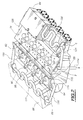
- FIG. 1 This figure therefore shows the plates 20 and 64 for supporting the actuators intake and exhaust valves, surfaces support 18.62 of these support plates, the entrances 25.69 of the chambers 24.68 receiving tails of intake and exhaust valves 14,56 and their actuating rods such as rod 36 ( Figure 1) and the orifices outlet 106,108 for supplying oil to the actuators from conduits 102, 104 as well as a main oil supply conduit 114 coming from of the housing.
- the conduits 102, 104 are channels axial which extend along the plates 20 and 64 and which provide lubrication of all actuators.
- the conduits 102 and 104 are interconnected by a connecting duct 116 which extends into the notch 115 for separating the plates 18 and 62 formed in the cylinder head 2.
- the support plates 20 and 64 are produced in one piece with the cylinder head 2.
- Figure 2 further shows that the engine to which the invention is applied is a four-cylinder, sixteen-valve engine, the cylinders being each provided with two intake and two exhaust valves.
- the electronic control units 84 and 86 when operating generate a significant amount of heat, in particular by the Joule effect.
- the motor is arranged in a current fresh air from the front of the vehicle.
- each control unit 84, 86 has a circuit for internal cooling 120, 122 formed for example either of a tubular coil arranged in the housing, either of cavities made directly in the body of the housing in heat exchange relationship with electronic components (not shown) that it contains.
- Each cooling circuit is supplied with water by two pipes 124, 126 and 128, 130 which connect the cooling circuit corresponding to the corresponding support plate 20, 64.
- the circulation of cooling water in the control boxes 84.86 prevents degradation by excessive temperature of the elements electronics contained in each of the boxes.
- control boxes 84 and 86 placed respectively above the air distributor 6 and the exhaust gas collector 52 limit the length electrical connections with the corresponding actuators 16 and 60.
- the fixing of the control boxes on supports linked to the engine allows the control boxes to follow in the event of a frontal impact from the vehicle, the movement of the motor and not to oppose the general deformation of the vehicle.
- the air distributor 6 which supports the control unit 84 improves filling and combustion in the engine thanks to the continuity of the shapes with the intake ducts 4 of the cylinder head 2.
- the circulation of fresh air inside the support 6 of the control unit 84 contributes to the cooling of the electronic components contained in said housing.
- the injectors are fixed on flanges, themselves attached to the air distributor.
Landscapes
- Engineering & Computer Science (AREA)
- Mechanical Engineering (AREA)
- General Engineering & Computer Science (AREA)
- Chemical & Material Sciences (AREA)
- Combustion & Propulsion (AREA)
- Valve Device For Special Equipments (AREA)
- Magnetically Actuated Valves (AREA)
- Characterised By The Charging Evacuation (AREA)
Abstract
Description
- le moteur est équipé de soupapes à actionneurs électromagnétiques à l'admission et à l'échappement et en ce qu'il comporte un boítier de commande disposé sur le répartiteur d'air d'admission et assurant la commande des actionneurs électromagnétiques des soupapes d'admission et des soupapes d'échappement,
- il est équipé de soupapes à actionneurs électromagnétiques à l'admission et à l'échappement et il comporte un boítier de commande disposé sur le répartiteur d'air d'admission et assurant la commande des actionneurs électromagnétiques des soupapes d'admission et un boítier de commande disposé sur le collecteur de gaz d'échappement du moteur et assurant la commande des actionneurs électromagnétiques des soupapes d'échappement,
- le boítier de commande des actionneurs des soupapes d'échappement est monté sur le collecteur des gaz d'échappement avec interposition d'éléments isolants thermiques,
- il comporte un circuit de refroidissement commun aux actionneurs et audit au moins un boítier de commande,
- le circuit de refroidissement des actionneurs et dudit au moins un boítier de commande fait partie du circuit de refroidissement du moteur,
- le circuit de refroidissement des actionneurs et dudit au moins un boítier de commande comporte des conduits d'eau ménagés dans la culasse le long des emplacements des actionneurs électromagnétiques et reliés d'une part au circuit général de refroidissement du moteur et d'autre part, à au moins un circuit de refroidissement interne d'au moins un boítier de commande par l'intermédiaire de canalisations de liaison,
- le circuit de refroidissement interne dudit au moins un boítier de commande comporte soit un dispositif du type serpentin tubulaire disposé dans le boítier, soit des cavités réalisées directement dans le corps du boítier en relation d'échange thermique avec les composants électroniques qu'il contient,
- il est prévu un circuit d'huile pour lubrifier les pièces mobiles des actionneurs électromagnétiques,
- le circuit d'huile de lubrification des pièces mobiles des actionneurs électromagnétiques fait partie du circuit d'huile du moteur,
- le circuit d'huile de lubrification des pièces mobiles des actionneurs électromagnétiques comporte des conduits axiaux s'étendant dans la culasse le long des emplacements des actionneurs, lesdits conduits étant alimentés en huile par un conduit principal d'amenée d'huile en provenance du carter du moteur, et étant reliés à des canaux de lubrification des actionneurs ménagés dans le corps des actionneurs et permettant d'amener l'huile de lubrification aux tiges mobiles desdits actionneurs électromagnétiques associés au moins aux soupapes d'admission,
- la culasse comporte au moins une platine de support des actionneurs électromagnétiques des soupapes d'admission et les conduits du circuit de refroidissement des actionneurs électromagnétiques d'une part et les conduits du circuit de lubrification des actionneurs électromagnétiques d'autre part, sont ménagés dans ladite platine,
- ladite platine est réalisée en une seule pièce avec la culasse,
- ladite platine est une pièce indépendante et est elle-même fixée sur la culasse du moteur,
- la culasse comporte une platine de support des actionneurs électromagnétiques des soupapes d'admission et une platine de support des actionneurs électromagnétiques des soupapes d'échappement, lesdites platines étant séparées entre elles par une échancrure de séparation,
- il comporte au moins un couvre-culasse assurant la protection des actionneurs électromagnétiques du moteur,
- il comporte un couvre-culasse de protection des actionneurs électromagnétiques des soupapes d'admission et un couvre-culasse de protection des actionneurs électromagnétiques des soupapes d'échappement,
- lesdits injecteurs et la rampe d'alimentation sont portés par le répartiteur d'air d'admission.
- la Fig.1 est une vue en coupe transversale d'un moteur thermique suivant l'invention ; et
- la Fig.2 est une vue en perspective avec arrachement partiel d'un moteur thermique équipé de soupapes à commande électromagnétique suivant l'invention, les actionneurs électromagnétiques étant enlevés.
Claims (18)
- Moteur thermique, caractérisé en ce qu'il est équipé de soupapes à actionneurs électromagnétiques (16,60) au moins à l'admission et d'au moins un boítier (84,86) de commande des actionneurs électromagnétiques (16,60) disposé au moins sur le répartiteur (6) d'air d'admission du moteur.
- Moteur thermique, caractérisé en ce que le moteur est équipé de soupapes à actionneurs électromagnétiques (16,60) à l'admission et à l'échappement et en ce qu'il comporte un boítier de commande (84) disposé sur le répartiteur d'air d'admission (6) et assurant la commande des actionneurs électromagnétiques (16,60) des soupapes d'admission (14) et des soupapes d'échappement (56).
- Moteur thermique suivant la revendication 1, caractérisé en ce qu'il est équipé de soupapes à actionneurs électromagnétiques (16,60) à l'admission et à l'échappement et en ce qu'il comporte un boítier de commande (84) disposé sur le répartiteur d'air d'admission (6) et assurant la commande des actionneurs électromagnétiques (16) des soupapes d'admission (14) et un boítier de commande (86) disposé sur le collecteur de gaz d'échappement (52) du moteur et assurant la commande des actionneurs électromagnétiques (60) des soupapes d'échappement (56).
- Moteur thermique suivant la revendication 3, caractérisé en ce que le boítier de commande (86) des actionneurs (60) des soupapes d'échappement (56) est monté sur le collecteur des gaz d'échappement (52) avec interposition d'éléments isolants thermiques (97).
- Moteur thermique suivant l'une des revendications 1 à 4, caractérisé en ce qu'il comporte un circuit de refroidissement (120,122,124,126,128, 130,132,134) commun aux actionneurs (16,60) et audit au moins un boítier de commande (84,86).
- Moteur thermique suivant la revendication 5, caractérisé en ce que le circuit de refroidissement (120,122,124,126,128, 130,132,134) des actionneurs et dudit au moins un boítier de commande fait partie du circuit de refroidissement du moteur.
- Moteur thermique suivant l'une des revendications 5 et 6, caractérisé en ce que le circuit de refroidissement des actionneurs et dudit au moins un boítier de commande comporte des conduits d'eau (192,194) ménagés dans la culasse (2) le long des emplacements des actionneurs électromagnétiques (16,60) et reliés d'une part au circuit général de refroidissement du moteur et d'autre part, à au moins un circuit de refroidissement interne (120,122) d'au moins un boítier de commande (84,86) par l'intermédiaire de canalisations de liaison (124,126,128,130).
- Moteur thermique suivant la revendication 7, caractérisé en ce que le circuit de refroidissement interne (120,122) dudit au moins un boítier de commande (84,86) comporte soit un dispositif du type serpentin tubulaire disposé dans le boítier, soit des cavités réalisées directement dans le corps du boítier, en relation d'échange thermique avec les composants électroniques qu'il contient.
- Moteur thermique suivant l'une des revendications 1 à 8, caractérisé en ce qu'il est prévu un circuit d'huile (102,104,106,108,110,112,114,116) pour lubrifier les pièces mobiles (36) des actionneurs électromagnétiques (16,60).
- Moteur thermique suivant la revendication 9, caractérisé en ce que le circuit d'huile de lubrification des pièces mobiles (36) des actionneurs électromagnétiques (16,60) fait partie du circuit d'huile du moteur.
- Moteur thermique suivant l'une des revendications 9 et 10, caractérisé en ce que le circuit d'huile de lubrification des pièces mobiles (36) des actionneurs électromagnétiques (16,60) comporte des conduits axiaux (102,104) s'étendant dans la culasse (2) le long des emplacements des actionneurs (16,60), lesdits conduits (102,104) étant alimentés en huile par un conduit principal d'amenée d'huile (114) en provenance du carter du moteur, et étant reliés à des canaux (106,108) de lubrification des actionneurs (16,60) ménagés dans le corps des actionneurs (16,60) et permettant d'amener l'huile de lubrification aux tiges mobiles (36) desdits actionneurs électromagnétiques (16,60) associés au moins aux soupapes d'admission (14,56).
- Moteur thermique suivant l'une des revendications 1 à 11, caractérisé en ce que la culasse (2) comporte au moins une platine (20) de support des actionneurs électromagnétiques (16) des soupapes d'admission (14) et en ce que les conduits (132,134) du circuit de refroidissement des actionneurs électromagnétiques d'une part et les conduits (102,106 et 104,108) du circuit de lubrification des actionneurs électromagnétiques d'autre part, sont ménagés dans ladite platine (20,64).
- Moteur thermique suivant la revendication 12, caractérisé en ce que ladite platine (20,64) est réalisée en une seule pièce avec la culasse.
- Moteur thermique suivant la revendication 12, caractérisé en ce que ladite platine est une pièce indépendante et est elle-même fixée sur la culasse du moteur.
- Moteur thermique suivant l'une des revendications 12 à 14, caractérisé en ce que la culasse comporte une platine (20) de support des actionneurs électromagnétiques (16) des soupapes d'admission (14) et une platine (64) de support des actionneurs électromagnétiques (60) des soupapes d'échappement (56), lesdites platines (20,64) étant séparées entre elles par une échancrure de séparation (115).
- Moteur thermique suivant l'une des revendications 1 à 15, caractérisé en ce qu'il comporte au moins un couvre-culasse (72,74) assurant la protection des actionneurs électromagnétiques (16,60) du moteur.
- Moteur thermique suivant les revendications 15 et 16, caractérisé en ce qu'il comporte un couvre-culasse (72) de protection des actionneurs électromagnétiques (16) des soupapes d'admission (14) et un couvre-culasse (74) de protection des actionneurs électromagnétiques des soupapes d'échappement (56).
- Moteur thermique suivant l'une des revendications 1 à 17, comprenant des injecteurs de combustible et une rampe d'alimentation en combustible des injecteurs, caractérisé en ce que lesdits injecteurs (28) et la rampe d'alimentation (29) sont portés par le répartiteur d'air d'admission (6).
Applications Claiming Priority (2)
| Application Number | Priority Date | Filing Date | Title |
|---|---|---|---|
| FR0016426 | 2000-12-15 | ||
| FR0016426A FR2818308B1 (fr) | 2000-12-15 | 2000-12-15 | Moteur thermique a soupapes a commande electromagnetique |
Publications (2)
| Publication Number | Publication Date |
|---|---|
| EP1217178A1 true EP1217178A1 (fr) | 2002-06-26 |
| EP1217178B1 EP1217178B1 (fr) | 2006-03-22 |
Family
ID=8857743
Family Applications (1)
| Application Number | Title | Priority Date | Filing Date |
|---|---|---|---|
| EP01402796A Expired - Lifetime EP1217178B1 (fr) | 2000-12-15 | 2001-10-26 | Moteur thermique à soupapes à commande électromagnétique |
Country Status (5)
| Country | Link |
|---|---|
| EP (1) | EP1217178B1 (fr) |
| AT (1) | ATE321193T1 (fr) |
| DE (1) | DE60118144T2 (fr) |
| ES (1) | ES2256186T3 (fr) |
| FR (1) | FR2818308B1 (fr) |
Citations (6)
| Publication number | Priority date | Publication date | Assignee | Title |
|---|---|---|---|---|
| DE19511880A1 (de) * | 1994-04-08 | 1995-10-12 | Audi Ag | Vorrichtung zum Betätigen von Gaswechsel-Ventilen |
| DE19756095A1 (de) * | 1997-12-17 | 1999-06-24 | Daimler Chrysler Ag | Vorrichtung zum Betrieb von Aktoren zur elektromagnetischen Ventilsteuerung bei Brennkraftmaschinen |
| DE19854542C1 (de) * | 1998-11-26 | 2000-04-13 | Daimler Chrysler Ag | Vorrichtung zur Kontaktierung eines Motorsteuergerätes |
| US6116570A (en) * | 1998-03-30 | 2000-09-12 | Siemens Automotive Corporation | Electromagnetic actuator with internal oil system and improved hydraulic lash adjuster |
| EP1057674A1 (fr) * | 1999-06-02 | 2000-12-06 | Isuzu Motors Limited | Dispositif pour la fixation d'une unité de contrôle électronique dans un compartiment moteur |
| WO2001025599A1 (fr) * | 1999-10-07 | 2001-04-12 | Heinz Leiber | Systeme electromagnetique de commande a soupapes |
Family Cites Families (1)
| Publication number | Priority date | Publication date | Assignee | Title |
|---|---|---|---|---|
| DE19923902A1 (de) * | 1999-05-25 | 2000-11-30 | Heinz Leiber | Verbrennungsmotor |
-
2000
- 2000-12-15 FR FR0016426A patent/FR2818308B1/fr not_active Expired - Fee Related
-
2001
- 2001-10-26 EP EP01402796A patent/EP1217178B1/fr not_active Expired - Lifetime
- 2001-10-26 ES ES01402796T patent/ES2256186T3/es not_active Expired - Lifetime
- 2001-10-26 AT AT01402796T patent/ATE321193T1/de not_active IP Right Cessation
- 2001-10-26 DE DE60118144T patent/DE60118144T2/de not_active Expired - Lifetime
Patent Citations (6)
| Publication number | Priority date | Publication date | Assignee | Title |
|---|---|---|---|---|
| DE19511880A1 (de) * | 1994-04-08 | 1995-10-12 | Audi Ag | Vorrichtung zum Betätigen von Gaswechsel-Ventilen |
| DE19756095A1 (de) * | 1997-12-17 | 1999-06-24 | Daimler Chrysler Ag | Vorrichtung zum Betrieb von Aktoren zur elektromagnetischen Ventilsteuerung bei Brennkraftmaschinen |
| US6116570A (en) * | 1998-03-30 | 2000-09-12 | Siemens Automotive Corporation | Electromagnetic actuator with internal oil system and improved hydraulic lash adjuster |
| DE19854542C1 (de) * | 1998-11-26 | 2000-04-13 | Daimler Chrysler Ag | Vorrichtung zur Kontaktierung eines Motorsteuergerätes |
| EP1057674A1 (fr) * | 1999-06-02 | 2000-12-06 | Isuzu Motors Limited | Dispositif pour la fixation d'une unité de contrôle électronique dans un compartiment moteur |
| WO2001025599A1 (fr) * | 1999-10-07 | 2001-04-12 | Heinz Leiber | Systeme electromagnetique de commande a soupapes |
Also Published As
| Publication number | Publication date |
|---|---|
| ES2256186T3 (es) | 2006-07-16 |
| DE60118144T2 (de) | 2007-03-08 |
| DE60118144D1 (de) | 2006-05-11 |
| FR2818308B1 (fr) | 2003-07-04 |
| FR2818308A1 (fr) | 2002-06-21 |
| ATE321193T1 (de) | 2006-04-15 |
| EP1217178B1 (fr) | 2006-03-22 |
Similar Documents
| Publication | Publication Date | Title |
|---|---|---|
| EP2336525B1 (fr) | Intégration d'un échangeur de chaleur air-liquide sur moteur | |
| FR2816004A1 (fr) | Ensemble de refroidissement pour vehicules a moteur | |
| FR2515729A1 (fr) | Moteur a combustion interne comportant un bloc-moteur et un demi-carter formes d'une seule piece | |
| JP6774388B2 (ja) | エンジンのブリーザ装置 | |
| BE1015284A3 (fr) | Collecteur d'admission de moteur hors-bord. | |
| EP1217178B1 (fr) | Moteur thermique à soupapes à commande électromagnétique | |
| FR2927278A1 (fr) | Support portant une articulation elastique et dote d'un dispositif de ventilation | |
| FR2851633A1 (fr) | Actionneur electromecanique de soupape equipee d'un systeme amortisseur | |
| FR2774635A1 (fr) | Dispositif de refroidissement du carburant d'un moteur de vehicule automobile | |
| EP1924767B1 (fr) | Module d'échange de chaleur pour la régulation en température d'un mélange de gaz admis dans un moteur thermique de véhicule automobile | |
| FR2660967A1 (fr) | Moteur a combustion interne a circuit de refroidissement perfectionne. | |
| EP3201441A1 (fr) | Actionneur electromagnetique pour soupape de moteur a combustion interne | |
| FR3064032A1 (fr) | Systeme d'admission pour moteur a combustion interne | |
| FR2920706A1 (fr) | Module multifonctionnel pour moteur a combustion interne | |
| WO2008145437A1 (fr) | Dispositif de regulation de la circulation d'un fluide dans un echangeur de chaleur, et module d'admission d'air associe | |
| EP4069951B1 (fr) | Decanteur d'huile comprenant une chambre d'air frais | |
| FR2980519A1 (fr) | Circuit d'huile pour moteur a combustion interne | |
| FR2936014A1 (fr) | Culasse de moteur a combustion integrant un collecteur d'echappement. | |
| FR2787518A1 (fr) | Systeme de rampe commune pour l'alimentation de moteurs a combustion interne | |
| EP3500746A1 (fr) | Conduit externe d'une sortie d'une volute d'une pompe a fluide caloporteur d'un moteur thermique d'un véhicule | |
| FR3026777A1 (fr) | Actionneur electromagnetique a refroidissement pour soupape de moteur a combustion interne | |
| EP2655824B1 (fr) | Systeme de motorisation et actionneur electromagnetique a refroidissement ameliore | |
| FR2914012A1 (fr) | Dispositif de ventilation d'un moteur a combustion interne dote d'un systeme anti-retour d'huile | |
| FR3062685A1 (fr) | Systeme de gestion d'air d'admission pour un moteur thermique de vehicule automobile | |
| EP1239136A1 (fr) | Culasse de moteur thermique comportant un élément supérieur formant couvre-culasse qui porte l'arbre à cames |
Legal Events
| Date | Code | Title | Description |
|---|---|---|---|
| PUAI | Public reference made under article 153(3) epc to a published international application that has entered the european phase |
Free format text: ORIGINAL CODE: 0009012 |
|
| AK | Designated contracting states |
Kind code of ref document: A1 Designated state(s): AT BE CH CY DE DK ES FI FR GB GR IE IT LI LU MC NL PT SE TR |
|
| AX | Request for extension of the european patent |
Free format text: AL;LT;LV;MK;RO;SI |
|
| 17P | Request for examination filed |
Effective date: 20021202 |
|
| AKX | Designation fees paid |
Designated state(s): AT BE CH CY DE DK ES FI FR GB GR IE IT LI LU MC NL PT SE TR |
|
| 17Q | First examination report despatched |
Effective date: 20040408 |
|
| GRAP | Despatch of communication of intention to grant a patent |
Free format text: ORIGINAL CODE: EPIDOSNIGR1 |
|
| GRAS | Grant fee paid |
Free format text: ORIGINAL CODE: EPIDOSNIGR3 |
|
| GRAA | (expected) grant |
Free format text: ORIGINAL CODE: 0009210 |
|
| AK | Designated contracting states |
Kind code of ref document: B1 Designated state(s): AT BE CH CY DE DK ES FI FR GB GR IE IT LI LU MC NL PT SE TR |
|
| PG25 | Lapsed in a contracting state [announced via postgrant information from national office to epo] |
Ref country code: IT Free format text: LAPSE BECAUSE OF FAILURE TO SUBMIT A TRANSLATION OF THE DESCRIPTION OR TO PAY THE FEE WITHIN THE PRESCRIBED TIME-LIMIT;WARNING: LAPSES OF ITALIAN PATENTS WITH EFFECTIVE DATE BEFORE 2007 MAY HAVE OCCURRED AT ANY TIME BEFORE 2007. THE CORRECT EFFECTIVE DATE MAY BE DIFFERENT FROM THE ONE RECORDED. Effective date: 20060322 Ref country code: AT Free format text: LAPSE BECAUSE OF FAILURE TO SUBMIT A TRANSLATION OF THE DESCRIPTION OR TO PAY THE FEE WITHIN THE PRESCRIBED TIME-LIMIT Effective date: 20060322 Ref country code: NL Free format text: LAPSE BECAUSE OF FAILURE TO SUBMIT A TRANSLATION OF THE DESCRIPTION OR TO PAY THE FEE WITHIN THE PRESCRIBED TIME-LIMIT Effective date: 20060322 Ref country code: IE Free format text: LAPSE BECAUSE OF FAILURE TO SUBMIT A TRANSLATION OF THE DESCRIPTION OR TO PAY THE FEE WITHIN THE PRESCRIBED TIME-LIMIT Effective date: 20060322 |
|
| REG | Reference to a national code |
Ref country code: GB Ref legal event code: FG4D Free format text: NOT ENGLISH |
|
| REG | Reference to a national code |
Ref country code: CH Ref legal event code: EP |
|
| REG | Reference to a national code |
Ref country code: IE Ref legal event code: FG4D Free format text: LANGUAGE OF EP DOCUMENT: FRENCH |
|
| REF | Corresponds to: |
Ref document number: 60118144 Country of ref document: DE Date of ref document: 20060511 Kind code of ref document: P |
|
| PG25 | Lapsed in a contracting state [announced via postgrant information from national office to epo] |
Ref country code: DK Free format text: LAPSE BECAUSE OF FAILURE TO SUBMIT A TRANSLATION OF THE DESCRIPTION OR TO PAY THE FEE WITHIN THE PRESCRIBED TIME-LIMIT Effective date: 20060622 Ref country code: SE Free format text: LAPSE BECAUSE OF FAILURE TO SUBMIT A TRANSLATION OF THE DESCRIPTION OR TO PAY THE FEE WITHIN THE PRESCRIBED TIME-LIMIT Effective date: 20060622 |
|
| REG | Reference to a national code |
Ref country code: ES Ref legal event code: FG2A Ref document number: 2256186 Country of ref document: ES Kind code of ref document: T3 |
|
| GBT | Gb: translation of ep patent filed (gb section 77(6)(a)/1977) |
Effective date: 20060703 |
|
| PG25 | Lapsed in a contracting state [announced via postgrant information from national office to epo] |
Ref country code: PT Free format text: LAPSE BECAUSE OF FAILURE TO SUBMIT A TRANSLATION OF THE DESCRIPTION OR TO PAY THE FEE WITHIN THE PRESCRIBED TIME-LIMIT Effective date: 20060822 |
|
| NLV1 | Nl: lapsed or annulled due to failure to fulfill the requirements of art. 29p and 29m of the patents act | ||
| PG25 | Lapsed in a contracting state [announced via postgrant information from national office to epo] |
Ref country code: CH Free format text: LAPSE BECAUSE OF NON-PAYMENT OF DUE FEES Effective date: 20061031 Ref country code: LI Free format text: LAPSE BECAUSE OF NON-PAYMENT OF DUE FEES Effective date: 20061031 Ref country code: MC Free format text: LAPSE BECAUSE OF NON-PAYMENT OF DUE FEES Effective date: 20061031 |
|
| REG | Reference to a national code |
Ref country code: IE Ref legal event code: FD4D |
|
| PLBE | No opposition filed within time limit |
Free format text: ORIGINAL CODE: 0009261 |
|
| STAA | Information on the status of an ep patent application or granted ep patent |
Free format text: STATUS: NO OPPOSITION FILED WITHIN TIME LIMIT |
|
| 26N | No opposition filed |
Effective date: 20061227 |
|
| REG | Reference to a national code |
Ref country code: CH Ref legal event code: PL |
|
| BERE | Be: lapsed |
Owner name: PEUGEOT CITROEN AUTOMOBILES SA Effective date: 20061031 |
|
| PG25 | Lapsed in a contracting state [announced via postgrant information from national office to epo] |
Ref country code: GR Free format text: LAPSE BECAUSE OF FAILURE TO SUBMIT A TRANSLATION OF THE DESCRIPTION OR TO PAY THE FEE WITHIN THE PRESCRIBED TIME-LIMIT Effective date: 20060623 |
|
| PG25 | Lapsed in a contracting state [announced via postgrant information from national office to epo] |
Ref country code: FI Free format text: LAPSE BECAUSE OF FAILURE TO SUBMIT A TRANSLATION OF THE DESCRIPTION OR TO PAY THE FEE WITHIN THE PRESCRIBED TIME-LIMIT Effective date: 20060322 |
|
| PG25 | Lapsed in a contracting state [announced via postgrant information from national office to epo] |
Ref country code: LU Free format text: LAPSE BECAUSE OF NON-PAYMENT OF DUE FEES Effective date: 20061026 Ref country code: TR Free format text: LAPSE BECAUSE OF FAILURE TO SUBMIT A TRANSLATION OF THE DESCRIPTION OR TO PAY THE FEE WITHIN THE PRESCRIBED TIME-LIMIT Effective date: 20060322 |
|
| PG25 | Lapsed in a contracting state [announced via postgrant information from national office to epo] |
Ref country code: CY Free format text: LAPSE BECAUSE OF FAILURE TO SUBMIT A TRANSLATION OF THE DESCRIPTION OR TO PAY THE FEE WITHIN THE PRESCRIBED TIME-LIMIT Effective date: 20060322 |
|
| PG25 | Lapsed in a contracting state [announced via postgrant information from national office to epo] |
Ref country code: BE Free format text: LAPSE BECAUSE OF FAILURE TO SUBMIT A TRANSLATION OF THE DESCRIPTION OR TO PAY THE FEE WITHIN THE PRESCRIBED TIME-LIMIT Effective date: 20061031 |
|
| PGFP | Annual fee paid to national office [announced via postgrant information from national office to epo] |
Ref country code: GB Payment date: 20120924 Year of fee payment: 12 |
|
| PGFP | Annual fee paid to national office [announced via postgrant information from national office to epo] |
Ref country code: IT Payment date: 20120925 Year of fee payment: 12 |
|
| PGFP | Annual fee paid to national office [announced via postgrant information from national office to epo] |
Ref country code: DE Payment date: 20120924 Year of fee payment: 12 Ref country code: FR Payment date: 20121115 Year of fee payment: 12 |
|
| PGFP | Annual fee paid to national office [announced via postgrant information from national office to epo] |
Ref country code: ES Payment date: 20120920 Year of fee payment: 12 |
|
| REG | Reference to a national code |
Ref country code: DE Ref legal event code: R082 Ref document number: 60118144 Country of ref document: DE Representative=s name: KOTITSCHKE & HEURUNG PARTNERSCHAFT MBB PATENT-, DE |
|
| GBPC | Gb: european patent ceased through non-payment of renewal fee |
Effective date: 20131026 |
|
| PG25 | Lapsed in a contracting state [announced via postgrant information from national office to epo] |
Ref country code: GB Free format text: LAPSE BECAUSE OF NON-PAYMENT OF DUE FEES Effective date: 20131026 |
|
| REG | Reference to a national code |
Ref country code: FR Ref legal event code: ST Effective date: 20140630 |
|
| REG | Reference to a national code |
Ref country code: DE Ref legal event code: R119 Ref document number: 60118144 Country of ref document: DE Effective date: 20140501 |
|
| PG25 | Lapsed in a contracting state [announced via postgrant information from national office to epo] |
Ref country code: FR Free format text: LAPSE BECAUSE OF NON-PAYMENT OF DUE FEES Effective date: 20131031 Ref country code: DE Free format text: LAPSE BECAUSE OF NON-PAYMENT OF DUE FEES Effective date: 20140501 Ref country code: IT Free format text: LAPSE BECAUSE OF NON-PAYMENT OF DUE FEES Effective date: 20131026 |
|
| REG | Reference to a national code |
Ref country code: ES Ref legal event code: FD2A Effective date: 20141107 |
|
| PG25 | Lapsed in a contracting state [announced via postgrant information from national office to epo] |
Ref country code: ES Free format text: LAPSE BECAUSE OF NON-PAYMENT OF DUE FEES Effective date: 20131027 |