EP1215937A2 - Fixationselement für ein implantierbares Mikrofon - Google Patents
Fixationselement für ein implantierbares Mikrofon Download PDFInfo
- Publication number
- EP1215937A2 EP1215937A2 EP01127286A EP01127286A EP1215937A2 EP 1215937 A2 EP1215937 A2 EP 1215937A2 EP 01127286 A EP01127286 A EP 01127286A EP 01127286 A EP01127286 A EP 01127286A EP 1215937 A2 EP1215937 A2 EP 1215937A2
- Authority
- EP
- European Patent Office
- Prior art keywords
- fixation element
- element according
- section
- auditory canal
- bore
- Prior art date
- Legal status (The legal status is an assumption and is not a legal conclusion. Google has not performed a legal analysis and makes no representation as to the accuracy of the status listed.)
- Granted
Links
Images






Classifications
-
- H—ELECTRICITY
- H04—ELECTRIC COMMUNICATION TECHNIQUE
- H04R—LOUDSPEAKERS, MICROPHONES, GRAMOPHONE PICK-UPS OR LIKE ACOUSTIC ELECTROMECHANICAL TRANSDUCERS; ELECTRIC HEARING AIDS; PUBLIC ADDRESS SYSTEMS
- H04R25/00—Electric hearing aids
- H04R25/60—Mounting or interconnection of hearing aid parts, e.g. inside tips, housings or to ossicles
- H04R25/604—Mounting or interconnection of hearing aid parts, e.g. inside tips, housings or to ossicles of acoustic or vibrational transducers
-
- H—ELECTRICITY
- H04—ELECTRIC COMMUNICATION TECHNIQUE
- H04R—LOUDSPEAKERS, MICROPHONES, GRAMOPHONE PICK-UPS OR LIKE ACOUSTIC ELECTROMECHANICAL TRANSDUCERS; ELECTRIC HEARING AIDS; PUBLIC ADDRESS SYSTEMS
- H04R2225/00—Details of deaf aids covered by H04R25/00, not provided for in any of its subgroups
- H04R2225/67—Implantable hearing aids or parts thereof not covered by H04R25/606
Definitions
- the present invention relates to a fixation element for an implantable microphone, that can be inserted into a hole that passes through the wall of the auditory canal.
- the fixation element comprises a cylindrical section, one with a Sound recording element provided part of the microphone on its outer circumference encloses and thereby leaves the sound entry membrane of the microphone free.
- the cylindrical Section is on the side facing the ear canal when implanted with projecting elastic flange parts that are in the implanted state place on the relevant side of the ear canal wall.
- On the ear canal facing away The cylindrical section is provided with another flange part, which lies in the implanted state on the other side of the ear canal wall.
- the flange parts and the cylindrical section form a sleeve, by means of which the microphone is attached to the ear canal wall.
- the cylindrical section is on its outside is smooth in order to lie against the bore wall.
- WO 97/36457 describes a fixation element for attaching a micro actuator an implantable hearing system in a hole in the promontory, wherein a sleeve-like part is inserted into the bore, which at one end a circumferential projecting flange is provided, which is located on one side of the promontory invests.
- the sleeve-like part is hollow cylindrical smooth outer surface.
- the hollow cylindrical section is provided with an area in which the inside and outside diameter of the hollow cylinder increases like a funnel.
- the cylindrical micro actuator is from the flange side of the sleeve-like Partly inserted into this and by means of a locking device formed on the flange locked.
- the first flange-like section can be moved particularly easily through the bore.
- fixation element is simple Way can be positioned in the hole as it is inserted into the hole This makes it easier for the slats to be folded inwards in the direction of insertion can be.
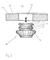
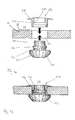
- FIGS. 1a, 1b and 2 show a first embodiment of a fixation element 10 shown that a substantially circular cylindrical portion 12 and one itself adjoining flange-like section 14 with a contact surface 16.
- the flange-like section 14 jumps in the radial direction with respect to the cylindrical Section 12 in front and encloses a sound sensor.
- the cylindrical section 12 and the flange section 14 are preferably designed as silicone sheathing, the cylindrical portion 12 having a sound absorbing element 32, such as encloses, for example, a membrane provided housing part 34 of the sensor.
- the Sound recording element is provided at the free end 18 of the cylindrical section 12 and is not provided with a jacket.
- the cylindrical section 12 has two circumferential, axially spaced apart arranged sealing lips 20 and 22 are provided, which consist of elastic material and taper towards the free end 18.
- the sealing lip 20 is close to the free End 18 provided, while the sealing lip 22 in the central region of the cylindrical Section 12 is provided.
- the sealing lips 20, 22 are, like the rest of the fixation element 10, preferably made of silicone.
- the sensor is connected to the electronics via an electrical connection, not shown implantable hearing system.
- the fixation element 10 is for implantation in the rear auditory canal wall 24 traversing bore 26 formed. On the side facing the auditory canal 30 the bony ear canal wall 24 is covered by the ear canal skin 28.
- the cylindrical section 12 of the side of the auditory canal wall 24 facing away from the auditory canal skin 28 into the bore 26 introduced.
- the outer circumference of the sealing lips 20 and 22 is larger than that Inner circumference of the bore 26. Due to the taper of the sealing lips 20 and their The sealing lips 20 and 22 become elastic in the radial direction towards the inside compressed, which causes elastic restoring forces that radially outward Act. If the cylindrical section 12 according to FIG. 1b completely into the bore 26 is introduced, the free end 18 with the membrane 32 is approximately flush with that with the Ear canal skin 28 provided side of the ear canal wall 24.
- the sealing lips 20, 22 sealingly on the wall of the bore 26 at, the sealing lips 20, 22 so by appropriate choice of materials and dimensions trained that the restoring forces are large enough to prevent the fixation element 10 in the direction of the side facing away from the auditory canal skin 28 canal wall 24 can move.
- the sealing lips 20, 22 are also designed so that when inserting the cylindrical portion 12 into the bore 26 through the forces occurring in the direction of the averted from the auditory canal skin 28 Can fold away side of the auditory canal wall 24 radially inwards.
- the sealing lip 22 is arranged in the axial direction so that it is in the inserted state near the end of the bore 26 on the bore wall facing away from the auditory canal skin 28 is applied in order to distribute the force over the bore as evenly as possible 26 to worry about.
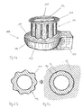
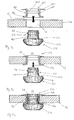
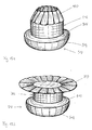
- FIGS. 3a to c show a fixation element 110 which is a cylindrical one Section 112, which at a free end 118, at which the sound entry membrane 32 lies with a circumferential, radially projecting, elastic Flange portion or a brim 136 is provided while at the other end flange-like section 114 is provided with a contact surface 116.
- a fixation element 110 which is a cylindrical one Section 112, which at a free end 118, at which the sound entry membrane 32 lies with a circumferential, radially projecting, elastic Flange portion or a brim 136 is provided while at the other end flange-like section 114 is provided with a contact surface 116.
- the cylindrical section 112 is on its outer circumference with web-like projections extending in the axial direction
- Elements 140 made of elastic material, which are designed so that there is a wavy contour in the circumferential direction (see FIG. 3b).
- the outer diameter of the cylindrical section 112 is in the region of the web-like protruding portion Elements 140 larger than the inner circumference of the bore 26 in the auditory canal wall 24 as long as the fixation element 110 is not inserted.
- the elements 140 are evenly distributed in the circumferential direction.
- the circumference of the flange 136 and its elasticity are chosen so that the flange 136 can be passed through the bore 26.
- the flange 136 thereby lies down first when inserted into the bore 26 to the rear.
- the flanged flange 136 forms a tapered section which introduces the section 112 relieved with the web-like protruding elements 140, these when entering be compressed in the bore 26 in the radial direction.
- the web-like protrusions are Elements 140 with respect to the state not used in the radial direction compressed, which creates elastic restoring forces, which on the one hand certain fixation of the cylindrical portion 112 in the axial direction of the bore 26 effect and on the other hand also centering the fixation element 110 in the bore 26 effect.
- fluctuations in diameter or Diameter deviations of the bore 26 in a certain tolerance range by Elasticity of the web-like elements 140 can be compensated.
- FIG. 8 shows a modification of the embodiment according to FIG. 3a
- the web-like protruding elements 140 are provided with slots 150 which are in the axial Seen in the direction of approximately V-shaped, each element 140 with provided with two such slots 150 which are offset from one another in the axial direction is.
- the open side of the slots 150 is the one with the flange 136 End of the cylindrical portion 112 directed.
- the effect of the slots 150 consists essentially in the fact that due to the elasticity of the elements 140 the respective Boundary of slot 150 which is closer to flange 136 (i.e. in Fig.
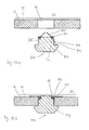
- the fixation element 210 shown in FIGS. 4a and 4b differs from the previously described embodiments essentially in that the cylindrical Section or nozzle 212 with a circumferential bulge 220 made of elastic Material is provided, which is designed so that when the fixation element is inserted 210 engages in a corresponding counterpart in the bore wall.
- the purpose of the bore 226 in the auditory canal wall 24 is in its central region a circumferential recess or undercut 222 provided in its contour corresponds to the bulge-like bulge 220 on the socket 212, but with the recess 222 is dimensioned somewhat smaller than the bulge 220, so that in introduced state act elastic restoring forces that ensure a tight fit of the Fixation element 210 provide.
- the bulge 220 is located approximately in the middle of the nozzle 212, so that when inserted Fixation element 210 the free end 218 of the fixation element 210 approximately flush with is the side of the auditory canal wall 24 facing the auditory canal skin 28.
- the contact surface 216 of the flange-like section 214 lies on the other side of the auditory canal wall 24 and provides additional fixation of the fixation element 210 by movement of the same in the direction of the auditory canal 30 is prevented.
- the bulge 220 ensures fixation of the fixation element thanks to its symmetrical design 210 in both directions. If a flange-like section 214 with contact surface 216 is present, however, it is not necessary that the bulge 220 and the Undercut 222 are symmetrical.
- the bulge 220 engages in the undercut 222 so that only the pulling out is prevented from the bore 226, for example by the bulge 220 in the the end facing the free end 218 tapers much more slowly than the other end The End.
- the insertion of the fixation element 210 into the bore 226 is due to the elasticity the bulge 220 enables.
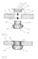
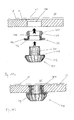
- Figures 5a and 5b show a fixation element 310, which in contrast to the embodiments described so far consist of two separate parts 320 and 322, which are brought into fixed engagement with one another only in the auditory canal bore 26.
- the main part 320 surrounds the as in the previously described embodiments Sound sensor and comprises a circular cylindrical section 312, to which a flange-like thickened section 314 connects with a contact surface 316.
- the sound absorption membrane 32 is provided at the end of the cylindrical section 312.
- the fastening part 322 comprises a sleeve-like section 330, on which an circumferential, radially projecting flange section 336 connects.
- the sleeve-like Section 330 has an axially extending from its free end, in Provided circumferentially distributed slots 332 and has in its central region on its inside a circumferential nose 334, which, as a dent in the wall of the sleeve-like section 330 is formed.
- the inside diameter of the sleeve-like Section 330 is selected so that the sleeve-like section 330 over the free end of the cylindrical portion 312 of the main body 320 can be slid, wherein however, spreading the sleeve-like portion 330 from its free end takes place, which causes elastic restoring forces necessary for a firm engagement of the sleeve-like Section 330, in particular its nose 334, with the peripheral surface of the cylindrical Section 312 provide, which is designed essentially as a smooth surface.
- the attachment part 322 can be made of, for example, a biocompatible metal, e.g. Titanium, or one suitable to achieve the required elastic restoring forces Be made of plastic.
- the fixation element 310 is implanted in such a way that the fastening part 322 introduced into the auditory canal 30 and on the ear canal skin 28 facing Side of bore 26 is placed while body 320 is on the other side the bore 26 is placed. Then the two parts 320, 322 in axial Moves towards each other and enter the bore 26, the sleeve-like Section 330 slides over the cylindrical section 312 as described above and ensures a tight engagement between the two parts 320 and 322. Naturally the main part 320 or the fastening part 322 can also be completely inserted into the first Hole 26 are introduced. In the implanted state, which is shown in Fig.
- the flange 336 of the fastening part 322 lies against that of the ear canal skin 28 facing side of the auditory canal wall 24, while the contact surface 316 of the Main 320 rests on the other side of the auditory canal wall 24, making for a Fixation of the fixation element 310 is provided in the bore 26.
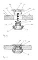
- the embodiment of the fixation element 410 shown in FIGS. 6a and 6b differs essentially from the embodiment just described by the way the axial engagement between the two separate ones Parts 420 and 422 of the fixation element 410 is produced. While in the embodiment according to Figures 5a and 5b the engagement by a clamping mechanism was produced, this takes place in the embodiment according to FIGS. 6a and 6b by mutual locking.
- a different geometry can be selected, for example a bevel according to FIGS. 6a and 6b bottom side of the protrusion 434 to insert the nozzle 412 into the to facilitate sleeve-like section 430.
- the one facing away from flange 436 The end of the sleeve-like section 430 is on its inside with a rounded portion 438 provided to facilitate the insertion of the connector 412.
- the implantation is carried out in the same way as in the embodiment according to FIGS Figures 5a and 5b.
- the Projection 434 locked with the recess 440, so that by contacting the flange 436 and the contact surface 416 on both sides of the auditory canal wall 24 a fixation of the fixation element 410 takes place in the bore 26.
- FIGS. 7a and 7b differs of the embodiment according to Figures 6a and 6b essentially in that the sleeve-like section 530 of the fastening part 522 on the inside circumferential recess 540 is provided, while the socket 512 for it on his The outer circumference is provided with the circumferential web-like projection 534. To do that This is to facilitate insertion of the socket 512 into the sleeve-like section 530 circumferential projection 534 on its side facing the fastening part 522 a rounding 542 provided.
- transition area between the nozzle 512 and the flange-like part 514 as a gradual increase in diameter, while in the embodiment according to Figures 6a and 6b and 5a and 5b Neck is also formed in this area with a constant diameter.
- the transition area is designated in FIGS. 7a and 7b with the reference symbol 544.
- fixation element 510 The implantation of the fixation element 510 is carried out analogously to that based on FIGS. 6a and 6b embodiment described.
- FIG. 9a to 9c differs from those previously described embodiments with two-part fixation element essentially in that the fastening part 622 at both ends of the sleeve-like section 630 is provided with a radially outwardly projecting flange 636 or 646, which rest in the implanted state on both sides of the auditory canal wall 24, so that the fastening part 622 is designed overall as a sleeve or as a spout.
- the sleeve-like section 630 has a circumferential recess on its inner circumference or groove 640, which is rounded trough-like in profile.
- the fastening part 622 is made of elastic material, preferably silicone.
- the socket 612 of the main part 620 is rounded on the outer circumference with a profile of the connector 612 circumferential web-like projection 634, the complementary is formed to the recess 640.
- the nozzle 612 accordingly instructs its free end a cylindrical portion and between the projection 634 and the flange-like section 614 a conical section 650 with increasing Outside diameter.
- the fastening part 622 is first of all removed during the implantation Ear canal side inserted into the bore 26 with the fastener 622 in front radially compresses the inserts, thereby flange-like portion 646 can be easily pushed into and through the bore 26.
- the flange 646 rests on the in the manner shown in Fig. 9b side of the auditory canal wall 24 facing away from the auditory canal skin 28.
- the fastening part 622 can be moved from the ear canal 30 instead of from the ear canal side opposite side of the auditory canal wall 24 are inserted into the bore 26.
- the main part 620 is then removed from the side facing away from the auditory canal skin 28 the auditory canal wall 24 with the free end of the socket 612 in the fastening part inserted until the projection 634 engages in the recess 640 and thereby the Main part 620 is fixed with respect to the fastening part 622.
- the one shown in Fig. 9c End position is the contact surface 616 of the flange-like section 614 on the Flange 646 of the fastening part 622.
- the free end of the nozzle 612 is in approximately flush with flange 636. Due to the conical design of section 650 a certain compression of the fastening part 622 is achieved in the bore 26, which for an improved sealing effect and stronger fixation of the fastening part 622 in the bore 26 provides.
- fixation element 710 also consists of a main part 720 and a fastening part 722, however the fastening part 722 only at one end of the sleeve-like section 730 Flange 746 provided, while at the other end a circumferential, elastic lip-like element 750 is provided.
- the bore 726 in the auditory canal wall 24 is provided on the side facing the ear canal skin 28 with a chamfer 727, while the rest of the bore is circular cylindrical.
- the lip-like element 750 In the implanted state, it is intended to rest in the chamfer 727 while the flange 746 for contact with the side of the auditory canal wall facing away from the auditory canal skin 28 24 is determined.
- the lip-like element 750 is in the uninserted state with respect to the direction of insertion or the free end of the sleeve-like section 730 towards the rear, the protruding part in the radial direction towards the inside like a handle is curved.
- the outer diameter of the sleeve-like portion 730 is in that Area 752, which adjoins the lip-like element 750, reduced by the Fold back the lip-like element 750 when it is inserted into the bore 726 facilitate.
- the fastening part 722 is thereby removed from the ear canal skin 28 facing away from the auditory canal wall 24 with the lip-like element 750 in front inserted into the bore 726 until finally the lip-like element for contact in the Chamfer 727 comes with elastic restoring forces that are large enough to close prevent the fastening part 722 from moving back in the direction of the Ear canal skin 28 can move away from the side of the auditory canal wall 24.
- the flange 746 comes to rest against the ear canal skin 28 opposite side of the auditory canal wall 24 and thus prevents the fastener 722 can slide further in the direction of the auditory canal 30.
- the inside of the sleeve-like section 730 is formed such that the inside diameter enlarged towards the two ends of the sleeve-like section 730, 10a, these two areas are conical and in the middle Area of the sleeve-like section 730 meet so that the inner diameter is minimal in the central area.
- a circumferential elastic angle part 754 provided as a reinforcement, both in sleeve-like section 730 as well as in the flange 746 and an angle of forms a little more than 90 ° and e.g. made of metal or a sufficiently strong plastic can exist.
- the main part 720 is provided with a circular cylindrical nozzle 712, on which a flange-like section 714 adjoins a contact surface 716.
- the nozzle 712 with its free end from the side of the auditory canal wall facing away from the auditory canal 30 24 inserted into the fastening part 722 positioned in the bore 726, until the free end of the socket 712 is flush with that of the ear canal skin 28 Side of the auditory canal wall 24 and the contact surface 716 on the flange 746 is applied.
- Figures 11a to 11c show a modification of this principle, the fixation element 810 is formed in one part instead of two parts.
- the Stub 812 of the fixation element 810 at its free end with the circumferential lip-like element 850 provided.
- the neck 812 is in the on the of the ear canal skin 28 facing side with a chamfer 727 provided bore 726 from the Ear canal skin 28 is introduced into the side of the auditory canal wall 24 facing away.
- FIG. 11b shows the state of the lip-like element 850 when it passes the circular-cylindrical one Portion of bore 726 shown. It can be seen that the lip-like element 850 is folded back in the insertion direction and in lies essentially flat in the area 852 with a reduced outer diameter, which facilitates the insertion of the connector 812.
- the lip-like element 850 lies in the chamfer 727, due to the diameter increase of the bore 726 in chamfer 727 again assumes a handle-like state.
- the contact surface 816 of flange-like section 814 lies in the state shown in FIG. 11c on that of the Ear canal skin 28 facing away from the side of the ear canal wall 24 by another To prevent the socket 812 from slipping into the auditory canal 30, so that the 11c is maintained, in which the free end of the nozzle 812 in essentially flush with the side of the auditory canal wall facing the auditory canal skin 28 24 lies.
- the lip-like element prevents contact 850 in the chamfer 727 a sliding back of the nozzle 812 in the direction of the Ear canal skin 28 facing away from the side of the auditory canal wall 24, so that an adequate Fixation of the fixation element 810 is achieved in the bore 726.
- Figures 12a, 12b, 13a and 13b show a further one-piece embodiment of a Fixation element 910.
- the connecting piece 912 which is essentially is designed as a circular cylinder, a set of lamellae is provided, which encircles arranged slats 920, which has one end 922 on the circumference of the Socket 912 are attached that they can be folded around this end 922.
- the Slats attached to a wire loop 924 running around the nozzle.
- the attachment can optionally be designed such that by means of suitable elements, e.g.
- Coil springs (not shown), a preload force is impressed on the lamellae 920, which the slats 920 from the position shown in Fig. 12a to that in Fig. 12b biased position shown, i.e. the preload acts so that the lamellae, seen from the free end of the nozzle 912, can be folded back.
- the Slats are preferably made of metal and are uniform in the circumferential direction distributed.
- the fins 920 Before insertion into the bore 26, the fins 920, from the free end of the Stub 912 seen from the front to the position shown in Figures 12a and 13a folded and held in this position. The free end of the slats 920 radially inwards. In this position, the fixation element 910 with the slats ahead from the side of the auditory canal wall 24 facing away from the auditory canal skin 28 inserted into the bore 26 until the free end 918 of the nozzle 912 is approximately flush with the side of the auditory canal wall 24 facing the auditory canal skin 28, as shown in FIG Fig. 12b is shown.
- the contact surface 916 of the flange-like section lies here 914, which adjoins the socket 912, on the side facing away from the auditory canal skin 28 Side of the ear canal wall 24, thereby preventing the neck 912 continues to slide towards the ear canal 30.
- the slats fold in this position 920 possibly supported by a pretension at its fastening point on the wire loop 924, to the rear and come to rest on the ear canal skin 28 facing side of the auditory canal wall 24.
- This position is in Figures 12b and 13b, the lamellae 920 forming a flat composite.
- the slats 920 are preferably designed such that they are in the Position when they abut the auditory canal wall 24, like tiles on their edges overlap to effect a bore 26 seal.
- FIGS. 14 and 15 show two further embodiments, in which one or both flanges by a plurality of retaining tabs distributed in the circumferential direction are replaced.
- a circular cylindrical section 60 is one Elements 70 provided with a circumferential flange-like section 62, which as resilient brim, preferably made of silicone, is formed and in a middle Section of the cylindrical section 60 is provided.
- a flange-like portion is provided, which consists of four in Distributed circumferential holding tabs 66, which radially at about 90 ° stand out and are evenly distributed over the circumference.
- a recess 68 is provided below the retaining tabs 66, which corresponds to the respective Holding tab 66 is dimensioned and it allows this, in the recess 68 to the rear (viewed from the free end 64) to fold to insert the cylindrical To facilitate section 60 in a corresponding auditory canal wall bore.
- the holding tabs 66 are designed to be elastic. After passing the hole due to the elastic restoring forces, the retaining tabs 66 fold back into the position shown in FIG. 14 shown position to the front and in this way cause by contact with the Ear wall fixation of the cylindrical portion 60. To fold this back To allow, the free end 64 of section 60 must be a bit over the end of the bore 26 are pushed into the auditory canal 30.
- the brim 62 succeeded a bit into the bore 26 and works because of it Elasticity to the rear. After the retaining tabs 66 are folded back, the Section 60 pulled back a little until the bottom of the tabs 66 on the Auditory canal wall. The brim 62 is now on the other side of the ear canal wall to fully fix the cylindrical portion 60 in the bore.
- the element 70 shown in FIG. 14 is preferably a hollow cylinder, in the interior as in the two-part embodiments described above with fastening part and main part the main part enclosing the sound sensor is inserted and is clamped or locked therein as described.
- the housing of the sound sensor can be glued inside the element 70 before insertion are, so that it is then a one-piece embodiment.
- FIG. 15 differs from the embodiment 14 essentially in that the brim 62 by a second set Retaining tabs 80 is replaced, which is formed analogously to the first set of retaining tabs 66 are, but are arranged offset by about 45 °.
- the Retaining tabs 80 also provide recesses 82 into which the lower retaining tabs 80 can dip if to cause the upper retaining tabs to unfold 66 the free end 64 is pushed a bit into the ear canal.
- Flange or "flange-like” or “flange section” etc. is intended in this application Denote element which is at about 90 degrees from a cylindrical section protrudes radially outwards and at least on one side with a preferably in essential flat contact surface is provided.
- the element can be around the cylindrical Circumferential section, i.e. with an approximately constant outer radius, or the outer radius can depend on the (rotation) angle, e.g. like a wavy Outer contour.
- the flange-like element can even be interrupted be, i.e. for example only from individual tabs distributed in the circumferential direction consist.
- circumferential in connection with “circumferential element” or the like. should not exclude certain interruptions, e.g. Slots or the like in the element can be provided.
- neck is meant a section that is both essentially cylindrical, in particular circular cylindrical, can be formed, as well as tapering or widening, in particular in the form of conical sections and the like.
- each for individual embodiments with a two-part fixation element described locking or jamming mechanisms for everyone other embodiments with a two-part fixation element can be used.
- Features of the embodiments with a one-piece fixation element can also be used be used in embodiments with a two-part fixation element, e.g. at the External circumferential bulges, sealing lips, etc. for fixing and / or sealing system on the bore wall instead of or in addition to flange-like Sections that line up against the ear canal wall.
- all can be in one piece described as two-part embodiments can be modified by the at the described one-piece embodiments as a socket or cylindrical section described area is formed as a separate sleeve-like part, in which a Trim a main part that encloses the sensor before or during implantation is inserted and locked or jammed.
- fixation element i.e. in the embodiments, in which the fixation element has a nozzle that at least partly lies directly against the wall of the bore, whereby a certain elasticity is required is suitable as a material, for example a biocompatible plastic with a Shore A hardness from 20 to 70, mainly silicone or polyurethane can act.
- Fixation element which comprises the sleeve-like section and on the bore wall is applied.
Landscapes
- Health & Medical Sciences (AREA)
- General Health & Medical Sciences (AREA)
- Neurosurgery (AREA)
- Otolaryngology (AREA)
- Physics & Mathematics (AREA)
- Engineering & Computer Science (AREA)
- Acoustics & Sound (AREA)
- Signal Processing (AREA)
- Headphones And Earphones (AREA)
- Prostheses (AREA)
- Details Of Audible-Bandwidth Transducers (AREA)
Abstract
Description
Claims (59)
- Fixationselement für ein implantierbares Mikrofon, wobei das Fixationselement (10, 210, 722, 810) einen im wesentlichen zylindrischen Abschnitt (12, 212, 730, 812) aufweist, der in eine die Gehörgangswand (24) durchquerende Bohrung (26, 226, 726) einsetzbar ist und mindestens bei implantiertem Fixationselement einen mit einem Schallaufnahmeelement (32, 34) versehenden Gehäuseteil des Mikrofons an dessen Außenumfang umschließt, dadurch gekennzeichnet, dass der zylindrische Abschnitt (12, 212, 730, 812) mindestens einen elastisch ausgebildeten Bereich (20, 22, 220, 750, 850) mit vergrößertem Außendurchmesser aufweist, der so ausgebildet ist, dass er durch Anlage an der Bohrungswand durch elastische Rückstellkräfte für eine hinreichende große Reibung sorgt, um den zylindrischen Abschnitt mindestens in einer der beiden axialen Richtungen der Bohrung (26, 226, 726) zu fixieren.
- Fixationselement nach Anspruch 1, dadurch gekennzeichnet, dass es sich bei Bereich mit vergrößertem Außendurchmesser um ein umlaufendes Dichtelement (20, 22) handelt, das so ausgebildet sind, dass es sich, wenn der zylindrische Abschnitt (12) in die Bohrung (26) eingesetzt ist, dichtend an die Bohrungswand anlegt.
- Fixationselement nach Anspruch 2, dadurch gekennzeichnet, dass mindestens zwei solcher Dichtelemente (20, 22) vorgesehen sind, die axial in Abstand zueinander angeordnet sind.
- Fixationselement nach Anspruch 3, dadurch gekennzeichnet, dass die Dichtelemente (20, 22) so ausgebildet sind, dass die Rückstellkräfte groß genug sind, um zu verhindern, dass sich das Fixationselement (10) in Richtung der von der Gehörgangshaut (28) abgewandten Seite der Gehörgangswand (24) bewegt.
- Fixationselement nach Anspruch 4, dadurch gekennzeichnet, dass der Außenumfang der Dichtelemente (20, 22) im nicht eingesetzten Zustand größer als der Innenumfang der Bohrung (26) ist.
- Fixationselement nach Anspruch 5, dadurch gekennzeichnet, dass die Dichtelemente als Dichtlippen (20, 22) ausgebildet sind.
- Fixationselement nach Anspruch 6, dadurch gekennzeichnet, dass die Dichtlippen (20, 22) so ausgebildet sind, dass sie durch die beim Einsetzen des zylindrischen Abschnitts (12) in die Bohrung (26) auftreten Kräfte in Richtung der der Gehörgangshaut (28) abgewandten Seite nach innen wegklappen.
- Fixationselement nach Anspruch 7, dadurch gekennzeichnet, dass sich die Dichtelemente (20, 22) auf ihrer der Gehörgangshaut (28) zugewandten Seite in Richtung der Gehörgangshaut verjüngen.
- Fixationselement nach Anspruch 3 bis 8, dadurch gekennzeichnet, dass das erste der Dichtelemente (20) an dem der Gehörgangshaut (28) zugewandten Ende des zylindrischen Abschnitts (12) angeordnet ist.
- Fixationselement nach Anspruch 9, dadurch gekennzeichnet, dass genau zwei Dichtelemente (20, 22) vorgesehen sind, wobei das zweite Dichtelement (22) axial soweit bezüglich der ersten versetzt ist, das es im eingesetzten Zustand nahe des von der Gehörgangshaut (28) abgewandten Endes der Bohrung (26) an der Bohrungswand anliegt.
- Fixationselement nach einem der Ansprüche 2 bis 10, dadurch gekennzeichnet, dass sich an den zylindrischen Abschnitt (12) ein flanschartiger Abschnitt (14) mit größeren Umfang anschließt, der im eingesetzten Zustand an der von der Gehörgangshaut (28) abgewandten Seite der Gehörgangswand anliegt.
- Fixationselement nach Anspruch 1, dadurch gekennzeichnet, dass der zylindrischen Abschnitt (212) in einem mittleren Bereich mit einer umlaufenden Auswölbung (220) versehen ist, die so ausgebildet ist, das sie bei eingesetztem Fixationselement in eine entsprechende umlaufende Ausnehmung (222) in der Bohrungswand eingreift.
- Fixationselement nach Anspruch 12, dadurch gekennzeichnet, dass die Auswölbung (220) so ausgebildet ist, dass der Eingriff der Auswölbung in die Ausnehmung (222) für die Fixierung des Mikrofons sorgt.
- Fixationselement nach Anspruch 12 oder 13, dadurch gekennzeichnet, dass die Auswölbung (220) wulstartig ausgebildet ist.
- Fixationselement nach einem der Ansprüche 12 bis 14, dadurch gekennzeichnet, dass sich an den zylindrischen Abschnitt (212) ein flanschartiger Abschnitt (214) anschließt, der im eingesetzten Zustand an der von der Gehörgangshaut (28) abgewandten Seite der Gehörgangswand (24) anliegt.
- Fixationselement nach Anspruch 1, dadurch gekennzeichnet, dass der zylindrische Abschnitt (730, 812) an einem Ende ein umlaufendes elastisches lippenartiges Element (750, 850) aufweist, wobei im implantierten Zustand des Fixationselements (720, 722, 810) das lippenartige Element in einer Fase (727) liegt, die an dem der Gehörgangshaut (28) zugewandten Ende der Bohrung (726) ausgebildet ist, wobei das lippenartige Element so ausgebildet ist, dass die auf das lippenartige Element wirkenden elastischen Rückstellkräfte groß genug sind, um zu verhindern, dass sich das Fixationselement in Richtung der von der Gehörgangshaut abgewandten Seite der Gehörgangswand (24) bewegt.
- Fixationselement nach Anspruch 16, dadurch gekennzeichnet, dass das lippenartige Element (750, 850) bezüglich der Einführrichtung nach hinten absteht.
- Fixationselement nach Anspruch 17, dadurch gekennzeichnet, dass der Außendurchmesser des zylindrischen Abschnitts (730, 812) in dem sich an das lippenartige Element (750, 850) anschließenden Bereich (752, 852) verringert ist, um das Zurückklappen des lippenartigen Elements beim Einführen in die Bohrung (726) zu erleichtern.
- Fixationselement nach Anspruch 16 bis 18, dadurch gekennzeichnet, dass der zylindrische Abschnitt (730, 812) an seinem anderen Ende mit einem Flanschteil (746, 814) versehen ist, welcher im implantierten Zustand an der von der Gehörgangshaut (28) abgewandten Seite der Gehörgangswand (24) anliegt.
- Fixationselement nach Anspruch 19, dadurch gekennzeichnet, dass der zylindrische Abschnitt von einem hülsenartigen Abschnitt (730) eines Befestigungsteils (722) gebildet wird, in den ein Stutzen (712) eines Hauptteils (720) einsetzbar ist, der den mit dem Schallaufnahmeelement versehenden Gehäuseteil umschließt.
- Fixationselement nach Anspruch 20, dadurch gekennzeichnet, dass das Befestigungsteil (722) für ein Einführen in die Bohrung (727) von der von der Gehörgangswand (28) abgewandten Seite ausgebildet ist.
- Fixationselement nach Anspruch 20 oder 21, dadurch gekennzeichnet, dass sich der Innendurchmesser des hülsenartigen Abschnitts (730) in Richtung der beiden Enden des hülsenartigen Abschnitts vergrößert.
- Fixationselement nach Anspruch 22, dadurch gekennzeichnet, dass die Innenseite des hülsenartigen Abschnitts (730) in beiden Endbereichen konisch ausgebildet ist.
- Fixationselement nach Anspruch 23, dadurch gekennzeichnet, dass die beiden konischen Bereiche im mittleren Bereich des hülsenartigen Abschnitt (730) aufeinandertreffen.
- Fixationselement nach einem der Ansprüche 20 bis 24, dadurch gekennzeichnet, dass das Befestigungsteil (722) im Bereich des flanschartigen Abschnitts (746) mit einem umlaufenden elastischen Winkelteil (754) verstärkt ist, das sowohl in dem hülsenartigen Abschnitt (730) als auch in dem flanschartigen Abschnitt (746) verläuft.
- Fixationselement für ein implantierbares Mikrofon, wobei das Fixationselement einen im wesentlichen zylindrischen Abschnitt (112) aufweist, der in eine die Gehörgangswand (24) durchquerende Bohrung (26) einsetzbar ist und einen mit einem Schallaufnahmeelement (32) versehenden Gehäuseteil des Mikrofons an dessen Außenumfang umschließt, wobei der zylindrische Abschnitt an beiden Enden mit jeweils mit einem Flanschteil (114, 136) versehen ist, das bei eingesetztem Fixationselement auf je einer Seite der Gehörgangswand anliegt, dadurch gekennzeichnet, dass der zylindrische Abschnitt (112) an seinem Außenumfang mit in axialer Richtung verlaufenden stegartig hervorstehenden Elementen (140) aus elastischem Material versehen ist, die so ausgebildet sind, dass sie sich, wenn der zylindrische Abschnitt in die Bohrung (26) eingesetzt ist, durch elastische Rückstellkräfte an die Bohrungswand anlegen.
- Fixationselement nach Anspruch 26, dadurch gekennzeichnet, dass die stegartig hervorstehenden Elemente (140) so ausgebildet sind, dass die Rückstellkräfte groß genug sind, um eine Fixierung des Mikrofons zu bewirken.
- Fixationselement nach Anspruch 26 oder 27, dadurch gekennzeichnet, dass der Außendurchmesser des zylindrischen Abschnitts (112) im Bereich der stegartig hervorstehenden Elemente (140) im nicht eingesetzten Zustand größer als der Innenumfang der Bohrung ist.
- Fixationselement nach einem der Ansprüche 26 bis 28, dadurch gekennzeichnet, dass die stegartig hervorstehenden Elemente (140) in Umfangsrichtung des zylindrischen Abschnitts (112) gleichmäßig verteilt sind.
- Fixationselement nach Anspruch 29, dadurch gekennzeichnet, dass die stegartig hervorstehenden Elemente (140) so ausgebildet sind, dass sich in Umfangsrichtung eine wellenförmige Kontur ergibt.
- Fixationselement nach einem der Ansprüche 26 bis 30, dadurch gekennzeichnet, dass die stegartig hervorstehenden Elemente (140) mit Schlitzen (150) versehen sind.
- Fixationselement nach Anspruch 31, dadurch gekennzeichnet, dass die Schlitze (150), in axialer Richtung gesehen, annähernd V- oder U-förmig ausgebildet sind.
- Fixationselement nach Anspruch 31 oder 32, dadurch gekennzeichnet, dass jedes die stegartig hervorstehende Element (140) mit mehreren in axialer Richtung versetzt zueinander angeordneten Schlitzen (150) versehen ist.
- Fixationselement für ein implantierbares Mikrofon, wobei das Fixationselement (310, 410, 510, 610) ein erstes Teil (320, 420, 520, 620) umfasst, das einen Stutzen (312, 412, 512, 612) aufweist, der in eine die Gehörgangswand (24) durchquerende Bohrung (26) einsetzbar ist und einen mit einem Schallaufnahmeelement (32) versehenden Gehäuseteil des Mikrofons an dessen Außenumfang umschließt, dadurch gekennzeichnet, dass das Fixationselement (310, 410, 510, 610) ein zweites Teil (70, 322, 422, 522, 622) umfasst, das einen hülsenartigen Abschnitt (60, 330, 430, 530, 630), der mit einem Ende über das freie Ende des Stutzens (312, 412, 512, 612) auf den Stutzen schiebbar und mit diesem zumindest in axialer Richtung in festen Eingriff bringbar ist, sowie einen ersten flanschartigen Abschnitt (66, 336, 436, 536, 636) aufweist, der an dem anderen Ende des hülsenartigen Abschnitts ausgebildet ist und im implantierten Zustand des Fixationselements an der der Gehörgangshaut (28) zugewandten Seite der Gehörgangswand (24) anliegt.
- Fixationselement nach Anspruch 34, dadurch gekennzeichnet, dass der Stutzen (312, 412, 512, 612) an einem Ende mit einem flanschartigen Bereich (314, 414, 514, 614) versehen ist, der bei eingesetztem Fixationselement auf der von der Gehörgangshaut (28) abgewandten Seite der Gehörgangswand (24) anliegt.
- Fixationselement nach Anspruch 34 oder 35, dadurch gekennzeichnet, dass der hülsenartige Abschnitt (330) in radialer Richtung elastisch ausgebildet ist und durch das Einführen des Stutzens (312) in den hülsenartigen Abschnitt von seinem freien Ende her aufgespreizt wird, wobei der feste Eingriff durch elastische Rückstellkräfte des aufgespreizten hülsenartigen Abschnitts vermittelt wird.
- Fixationselement nach Anspruch 36, dadurch gekennzeichnet, dass der hülsenartige Abschnitt (330) von seinem freien Ende her mit in axialer Richtung verlaufenden, in Umfangsrichtung verteilten Schlitzen (332) versehen ist.
- Fixationselement nach Anspruch 36 oder 37, dadurch gekennzeichnet, dass hülsenartige Abschnitt (330) in seinem mittleren Bereich auf seiner Innenseite mit einer umlaufenden Nase (334) versehen ist, die im implantierten Zustand des Fixationselements (310) an dem Außenumfang des Stutzens (312) anliegt und für den festen Eingriff sorgt.
- Fixationselement nach Anspruch 34 oder 35, dadurch gekennzeichnet, dass der hülsenartige Abschnitt (430, 530, 630) und der Stutzen (412, 512, 612) für eine wechselseitige Verrastung ausgebildet sind, um den festen Eingriff zu bewirken.
- Fixationselement nach Anspruch 39, dadurch gekennzeichnet, dass der hülsenartige Abschnitt (530, 630) auf seiner Innenseite mit einer umlaufenden Aussparung (540, 640) versehen ist und der Stutzen (512, 612) an seinem Außenumfang mit einer umlaufenden stegartigen Auswölbung (534, 634) versehen ist, die im implantierten Zustand des Fixationselements (510, 610) in die Aussparung eingreift.
- Fixationselement nach Anspruch 39, dadurch gekennzeichnet, dass der Stutzen (412) auf seiner Außenseite mit einer umlaufenden Aussparung (440) versehen ist und der hülsenartige Abschnitt (430) an seiner Innenseite mit einer umlaufenden stegartigen Auswölbung (434) versehen ist, die im implantierten Zustand des Fixationselements (410) in die Aussparung eingreift.
- Fixationselement nach Anspruch 39 bis 41, dadurch gekennzeichnet, dass im Bereich des freien Endes des hülsenartigen Abschnitts (430, 530, 630) des zweiten Teils der Innendurchmesser zunimmt.
- Fixationselement nach Anspruch 34, dadurch gekennzeichnet, dass das zweite Teil (70, 622) einen zweiten flanschartigen Abschnitt (62, 646) an dem Ende des hülsenartigen Abschnitts (60, 630) aufweist, das über das freie Ende des Stutzens (612) auf den Stutzen schiebbar ist, wobei im implantierten Zustand des Fixationselements (610) der zweite flanschartige Abschnitt an der von der Gehörgangshaut (28) abgewandten Seite der Gehörgangswand (24) anliegt.
- Fixationselement nach Anspruch 43, dadurch gekennzeichnet, dass der erste flanschartige Abschnitt aus mehreren in Umfangsrichtung verteilten Haltelaschen (66) besteht.
- Fixationselement nach Anspruch 43 oder 44, dadurch gekennzeichnet, dass der zweite flanschartige Abschnitt aus mehreren in Umfangsrichtung verteilten Haltelaschen (80) besteht.
- Fixationselement nach Anspruch 43, dadurch gekennzeichnet, dass der Stutzen (612) einen konischen Abschnitt (650) aufweist, der sich zu dem dem freien Ende des Stutzens gegenüberliegenden Ende hin verbreitert.
- Fixationselement für ein implantierbares Mikrofon, wobei das Fixationselement (70) einen zylindrischen Abschnitt (60) aufweist, der in eine die Gehörgangswand durchquerende Bohrung (26) einsetzbar ist und einen mit einem Schallaufnahmeelement versehenden Gehäuseteil des Mikrofons am dessen Außenumfang umschließt, wobei der zylindrische Abschnitt an einem Ende mit einem ersten flanschartigen Bereich (66), der bei implantiertem Fixationselement an der der Gehörgangshaut (28) zugewandten Seite der Gehörgangswand (24) anliegt, und mit einem zweiten flanschartigen Bereich (62, 80) versehen ist, der bei implantiertem Fixationselement an der von der Gehörgangshaut abgewandten Seite der Gehörgangswand anliegt, dadurch gekennzeichnet, dass der erste flanschartige Bereich aus mehreren in Umfangsrichtung verteilten elastischen Haltelaschen (66) besteht, wobei in dem Außenumfang des zylindrischen Abschnitts für jede Haltelasche eine Aussparung (68) vorgesehen ist, die so ausgebildet ist, dass die entsprechende Haltelasche in die Aussparung abklappen kann, um das Einführen des zylindrischen Abschnitts (60) in die Bohrung (26) zu erleichtern.
- Fixationselement nach Anspruch 47, dadurch gekennzeichnet, dass der zweite flanschartige Abschnitt (62, 80) elastisch ausgebildet ist.
- Fixationselement nach Anspruch 48, dadurch gekennzeichnet, dass der zweite flanschartige Abschnitt aus mehreren in Umfangsrichtung verteilten Haltelaschen (80) besteht, wobei in dem Außenumfang des zylindrischen Abschnitts (60) für jede dieser Haltelaschen eine Aussparung (82) vorgesehen ist, die so ausgebildet ist, dass die entsprechende Haltelasche in die Aussparung abklappen kann.
- Fixationselement nach Anspruch 49, dadurch gekennzeichnet, dass die Haltelaschen (66) des ersten flanschartigen Abschnitts bzgl. den Haltelaschen des zweiten flanschartigen Abschnitts (80) in Umfangsrichtung zueinander versetzt sind.
- Fixationselement nach Anspruch 47 bis 50, dadurch gekennzeichnet, dass die Haltelaschen (66, 80) in Umfangsrichtung gleichmäßig verteilt sind.
- Fixationselement für ein implantierbares Mikrofon, wobei das Fixationselement (910) einen Stutzen (912) aufweist, der in eine die Gehörgangswand (24) durchquerende Bohrung (26) einsetzbar ist und einen mit einem Schallaufnahmeelement versehenden Gehäuseteil des Mikrofons am dessen Außenumfang umschließt, dadurch gekennzeichnet, dass der Stutzen (912) an einem Ende mit umlaufenden Lamellen (920) versehen ist, die mit einem Ende (922) derart an dem Umfang des Stutzens (912) befestigt sind, dass sie um dieses Ende klappbar sind, wobei die Lamellen im implantierten Zustand des Fixationselements (910) an der der Gehörgangshaut (28) zugewandten Seite der Gehörgangswand (24) anliegen.
- Fixationselement nach Anspruch 52, dadurch gekennzeichnet, dass die Lamellen (920) an einer um den Stutzen (912) umlaufenden Drahtschleife (924) befestigt sind.
- Fixationselement nach Anspruch 52 oder 53, dadurch gekennzeichnet, dass die Lamellenbefestigung so ausgebildet ist, dass auf die Lamellen (920) Rückstellkräfte in Richtung der Stellung wirken, in welcher die Lamellen an der der Gehörgangshaut (28) zugewandten Seite der Gehörgangswand (24) anliegen, wobei die Rückstellkraft vorzugsweise jeweils von einer Feder aufgebracht wird.
- Fixationselement nach einem der Ansprüche 52 bis 54, dadurch gekennzeichnet, dass die Lamellen (920) gleichmäßig in Umfangsrichtung verteilt sind.
- Fixationselement nach Anspruch 55, dadurch gekennzeichnet, dass die Lamellen (920) im dem Zustand, wenn sie an der der Gehörgangshaut (28) zugewandten Seite der Gehörgangswand (24) anliegen, einen flächigen Verbund bilden.
- Fixationselement nach Anspruch 56, dadurch gekennzeichnet, dass die Lamellen (920) im dem Zustand, wenn sie an der der Gehörgangshaut (28) zugewandten Seite der Gehörgangswand (24) anliegen, dachziegelartig überlappen.
- Fixationselement nach einem der Ansprüche 52 bis 57, dadurch gekennzeichnet, dass die Lamellen (920) aus biokompatiblem Metall, beispielsweise Titan, gefertigt sind.
- Fixationselement nach einem der Ansprüche 52 bis 58, dadurch gekennzeichnet, dass der Stutzen (912) an dem von den Lamellen (920) abgewandten Ende mit einem flanschartigen Bereich (914) versehen ist, der bei implantiertem Fixationselement an der von der Gehörgangshaut (28) abgewandten Seite der Gehörgangswand anliegt.
Applications Claiming Priority (2)
| Application Number | Priority Date | Filing Date | Title |
|---|---|---|---|
| DE10062236 | 2000-12-14 | ||
| DE10062236A DE10062236C2 (de) | 2000-12-14 | 2000-12-14 | Fixationselement für ein implantierbares Mikrofon |
Publications (3)
| Publication Number | Publication Date |
|---|---|
| EP1215937A2 true EP1215937A2 (de) | 2002-06-19 |
| EP1215937A3 EP1215937A3 (de) | 2010-04-14 |
| EP1215937B1 EP1215937B1 (de) | 2013-01-09 |
Family
ID=7667069
Family Applications (1)
| Application Number | Title | Priority Date | Filing Date |
|---|---|---|---|
| EP01127286A Expired - Lifetime EP1215937B1 (de) | 2000-12-14 | 2001-11-16 | Fixationselement für ein implantierbares Mikrofon |
Country Status (6)
| Country | Link |
|---|---|
| US (2) | US7058192B2 (de) |
| EP (1) | EP1215937B1 (de) |
| JP (1) | JP2002218596A (de) |
| AU (1) | AU780508B2 (de) |
| CA (2) | CA2675655A1 (de) |
| DE (1) | DE10062236C2 (de) |
Cited By (4)
| Publication number | Priority date | Publication date | Assignee | Title |
|---|---|---|---|---|
| EP1626612A3 (de) * | 2004-08-11 | 2009-05-06 | Sonion Nederland B.V. | Montagestruktur eines Hörhilfegerätsmikrofons und Montageverfahren dafür |
| WO2011036310A3 (en) * | 2011-01-11 | 2011-11-24 | Advanced Bionics Ag | Implantable actuator for direct cochlea stimulation |
| EP2645742A1 (de) * | 2012-03-30 | 2013-10-02 | Oticon A/S | Cerumenfilter and Handhabungsgerät für solche Filter |
| EP1868512A4 (de) * | 2005-03-22 | 2014-06-18 | S George Lesinski | Implantation eines therapeutischen geräts in die cochlea |
Families Citing this family (27)
| Publication number | Priority date | Publication date | Assignee | Title |
|---|---|---|---|---|
| DE10062236C2 (de) * | 2000-12-14 | 2003-11-27 | Phonak Ag Staefa | Fixationselement für ein implantierbares Mikrofon |
| DE10320861B3 (de) * | 2003-05-09 | 2004-12-02 | Siemens Audiologische Technik Gmbh | Cerumenschutzeinrichtung |
| US7844344B2 (en) | 2004-03-30 | 2010-11-30 | Medtronic, Inc. | MRI-safe implantable lead |
| KR100675027B1 (ko) | 2005-08-10 | 2007-01-30 | 주식회사 비에스이 | 실리콘 콘덴서 마이크로폰 및 이를 위한 실장 방법 |
| KR100644730B1 (ko) * | 2005-08-20 | 2006-11-10 | 주식회사 비에스이 | 실리콘 콘덴서 마이크로폰 |
| KR100673848B1 (ko) | 2005-08-29 | 2007-01-24 | 주식회사 비에스이 | 삽입 실장형 콘덴서 마이크로 폰과 이를 구비하는 마더보드 |
| US8014871B2 (en) * | 2006-01-09 | 2011-09-06 | Cochlear Limited | Implantable interferometer microphone |
| KR100673849B1 (ko) * | 2006-01-18 | 2007-01-24 | 주식회사 비에스이 | 메인보드에 실장되는 콘덴서 마이크로폰 및 이를 포함하는이동통신 단말기 |
| US9578429B2 (en) * | 2006-11-09 | 2017-02-21 | Sonova Ag | Support mount for electronic components |
| US9044593B2 (en) | 2007-02-14 | 2015-06-02 | Medtronic, Inc. | Discontinuous conductive filler polymer-matrix composites for electromagnetic shielding |
| US8483842B2 (en) | 2007-04-25 | 2013-07-09 | Medtronic, Inc. | Lead or lead extension having a conductive body and conductive body contact |
| KR100952215B1 (ko) * | 2007-07-23 | 2010-04-09 | 박기범 | 이어 러버 |
| DE102007058987B3 (de) * | 2007-12-07 | 2009-07-16 | Siemens Medical Instruments Pte. Ltd. | Stirnplatte mit Verschlussvorrichtung |
| JP5005525B2 (ja) * | 2007-12-18 | 2012-08-22 | 株式会社オーディオテクニカ | 埋め込み式マイクロホン装置 |
| US9037263B2 (en) | 2008-03-12 | 2015-05-19 | Medtronic, Inc. | System and method for implantable medical device lead shielding |
| US8363871B2 (en) * | 2008-03-31 | 2013-01-29 | Cochlear Limited | Alternative mass arrangements for bone conduction devices |
| KR101452503B1 (ko) * | 2008-06-16 | 2014-10-21 | 한라비스테온공조 주식회사 | 압축기용 오일유출 방지구 |
| US9205253B2 (en) | 2009-04-30 | 2015-12-08 | Medtronic, Inc. | Shielding an implantable medical lead |
| WO2010135440A1 (en) * | 2009-05-22 | 2010-11-25 | Medtronic, Inc. | A cover having self-anchoring protrusions for use with an implantable medical device |
| JP5415627B2 (ja) * | 2010-01-25 | 2014-02-12 | ジアンス ベターライフ メディカル カンパニー リミテッド | 耳用モジュール及び開放式耳内受話補聴装置 |
| EP2838609B1 (de) | 2012-04-19 | 2019-03-06 | Medtronic, Inc. | Gepaarte medizinische führungselemente mit geflochtenen leitfähigen abschirmungen mit verschiedenen physikalischen parameterwerten |
| US9167362B2 (en) * | 2012-09-13 | 2015-10-20 | Otokinetics Inc. | Implantable receptacle for a hearing aid component |
| US9993638B2 (en) | 2013-12-14 | 2018-06-12 | Medtronic, Inc. | Devices, systems and methods to reduce coupling of a shield and a conductor within an implantable medical lead |
| US9998837B2 (en) | 2014-04-29 | 2018-06-12 | Cochlear Limited | Percutaneous vibration conductor |
| WO2016014427A1 (en) | 2014-07-23 | 2016-01-28 | Medtronic, Inc. | Methods of shielding implantable medical leads and implantable medical lead extensions |
| WO2016014816A1 (en) | 2014-07-24 | 2016-01-28 | Medtronic, Inc. | Methods of shielding implantable medical leads and implantable medical lead extensions |
| JP6832507B2 (ja) * | 2016-03-01 | 2021-02-24 | パナソニックIpマネジメント株式会社 | マイクアレイ装置、マイクアレイシステム及びマイクアレイ装置の製造方法 |
Family Cites Families (12)
| Publication number | Priority date | Publication date | Assignee | Title |
|---|---|---|---|---|
| DE3736591C3 (de) * | 1987-04-13 | 1994-04-14 | Beltone Electronics Corp | Hörgerät mit Ohrschmalzschutz |
| US5772575A (en) * | 1995-09-22 | 1998-06-30 | S. George Lesinski | Implantable hearing aid |
| WO1997036457A1 (en) * | 1996-03-25 | 1997-10-02 | Lesinski S George | Attaching an implantable hearing aid microactuator |
| DE69733837T2 (de) * | 1996-05-24 | 2006-04-27 | Lesinski, S. George, Cincinnati | Verbesserte mikrophone für implantierbares hörhilfegerät |
| DE19752447C2 (de) * | 1997-11-26 | 1999-12-30 | Implex Hear Tech Ag | Fixationselement für ein implantierbares Mikrofon |
| DE19758573C2 (de) * | 1997-11-26 | 2001-03-01 | Implex Hear Tech Ag | Fixationselement für ein implantierbares Mikrofon |
| DK174632B1 (da) * | 1998-07-10 | 2003-07-28 | Toepholm & Westermann | Ørevoksfang til i-øret-høreapparat samt hjælpemiddel til brug ved dets isætning og udtagning |
| DE19859171C2 (de) * | 1998-12-21 | 2000-11-09 | Implex Hear Tech Ag | Implantierbares Hörgerät mit Tinnitusmaskierer oder Noiser |
| EP1210841B1 (de) * | 1999-09-09 | 2011-08-03 | Nokia Siemens Networks GmbH & Co. KG | Verfahren zur realisierung eines rückruf-dienstes in einem mobilfunknetz |
| DE10062236C2 (de) * | 2000-12-14 | 2003-11-27 | Phonak Ag Staefa | Fixationselement für ein implantierbares Mikrofon |
| US6786860B2 (en) * | 2001-10-03 | 2004-09-07 | Advanced Bionics Corporation | Hearing aid design |
| US7127078B2 (en) * | 2001-10-03 | 2006-10-24 | Advanced Bionics Corporation | Implanted outer ear canal hearing aid |
-
2000
- 2000-12-14 DE DE10062236A patent/DE10062236C2/de not_active Expired - Fee Related
-
2001
- 2001-11-16 EP EP01127286A patent/EP1215937B1/de not_active Expired - Lifetime
- 2001-11-30 AU AU95217/01A patent/AU780508B2/en not_active Ceased
- 2001-12-10 US US10/010,155 patent/US7058192B2/en not_active Expired - Fee Related
- 2001-12-11 CA CA002675655A patent/CA2675655A1/en not_active Abandoned
- 2001-12-11 CA CA2364811A patent/CA2364811C/en not_active Expired - Fee Related
- 2001-12-13 JP JP2001379950A patent/JP2002218596A/ja active Pending
-
2006
- 2006-05-18 US US11/419,083 patent/US8073174B2/en not_active Expired - Fee Related
Cited By (6)
| Publication number | Priority date | Publication date | Assignee | Title |
|---|---|---|---|---|
| EP1626612A3 (de) * | 2004-08-11 | 2009-05-06 | Sonion Nederland B.V. | Montagestruktur eines Hörhilfegerätsmikrofons und Montageverfahren dafür |
| US7961899B2 (en) | 2004-08-11 | 2011-06-14 | Sonion Nederland B.V. | Hearing aid microphone mounting structure and method for mounting |
| EP1868512A4 (de) * | 2005-03-22 | 2014-06-18 | S George Lesinski | Implantation eines therapeutischen geräts in die cochlea |
| WO2011036310A3 (en) * | 2011-01-11 | 2011-11-24 | Advanced Bionics Ag | Implantable actuator for direct cochlea stimulation |
| EP2645742A1 (de) * | 2012-03-30 | 2013-10-02 | Oticon A/S | Cerumenfilter and Handhabungsgerät für solche Filter |
| US8824714B2 (en) | 2012-03-30 | 2014-09-02 | Oticon A/S | Earwax filter, handing tool and dispenser for such filter |
Also Published As
| Publication number | Publication date |
|---|---|
| CA2364811C (en) | 2010-10-19 |
| AU9521701A (en) | 2002-06-20 |
| CA2675655A1 (en) | 2002-06-14 |
| DE10062236C2 (de) | 2003-11-27 |
| DE10062236A1 (de) | 2002-07-04 |
| US20020076075A1 (en) | 2002-06-20 |
| US7058192B2 (en) | 2006-06-06 |
| CA2364811A1 (en) | 2002-06-14 |
| JP2002218596A (ja) | 2002-08-02 |
| AU780508B2 (en) | 2005-03-24 |
| EP1215937A3 (de) | 2010-04-14 |
| US20060233410A1 (en) | 2006-10-19 |
| EP1215937B1 (de) | 2013-01-09 |
| US8073174B2 (en) | 2011-12-06 |
Similar Documents
| Publication | Publication Date | Title |
|---|---|---|
| DE10062236C2 (de) | Fixationselement für ein implantierbares Mikrofon | |
| DE19828059C2 (de) | Anschlußarmatur mit einem durch Schlitze in Haltezungen aufgeteilten Befestigungsvorsprung | |
| DE10021377C2 (de) | Rundsteckverbinder | |
| DE4115791C1 (de) | ||
| DE2755674C2 (de) | Befestigungsvorrichtung | |
| DE10055647B4 (de) | Hilfsgriffsbefestigungsstruktur und -verfahren | |
| DE10032010C1 (de) | Anschlußarmatur mit elastischem Ring als Anschlag | |
| EP1098611B1 (de) | Hüftpfannenprothese | |
| DE202008010262U1 (de) | Verbindungsbaugruppe zur Befestigung eines Anbauelements auf einem Trägerelement | |
| DE19804719C1 (de) | Anschlußarmatur mit axial vorstehendem Befestigungsvorsprung | |
| EP1228331A1 (de) | Anschlussarmatur für umfangsgerippte längliche körper mit einem einrastenden haltevorsprung | |
| DE102012003337A1 (de) | Befestigungsvorrichtung | |
| DE102016014628A1 (de) | Clip zum Befestigen eines ersten Elements an einem zweiten Element | |
| DE202005021582U1 (de) | Kabeldurchführung | |
| DE3012733A1 (de) | Elektrischer verbinder | |
| EP1121554A1 (de) | Befestigungskupplung für wellrohre | |
| CH705378B1 (de) | Kabelverschraubung. | |
| DE2031404A1 (de) | Befestigungsstift | |
| DE2604325C3 (de) | Wischvorrichtung für Scheiben von Kraftfahrzeugen | |
| DE3603876C2 (de) | ||
| EP1644205A1 (de) | Gleitschutzstift | |
| DE3008772C2 (de) | Zigarettenanzünder, insbesondere für Kraftfahrzeuge | |
| DE69936961T2 (de) | Gehäuse, insbesondere für elektrische Geräte, dessen Rückwand mit mindestens einem, mit einer Kappe abgedeckten Loch versehen ist | |
| EP1006307A1 (de) | Steckkupplung | |
| WO2007012396A1 (de) | Kugelgelenk und dichtungsmanschette für ein solches kugelgelenk |
Legal Events
| Date | Code | Title | Description |
|---|---|---|---|
| PUAI | Public reference made under article 153(3) epc to a published international application that has entered the european phase |
Free format text: ORIGINAL CODE: 0009012 |
|
| AK | Designated contracting states |
Kind code of ref document: A2 Designated state(s): AT BE CH CY DE DK ES FI FR GB GR IE IT LI LU MC NL PT SE TR |
|
| AX | Request for extension of the european patent |
Free format text: AL;LT;LV;MK;RO;SI |
|
| RAP1 | Party data changed (applicant data changed or rights of an application transferred) |
Owner name: PHONAK AG |
|
| PUAL | Search report despatched |
Free format text: ORIGINAL CODE: 0009013 |
|
| AK | Designated contracting states |
Kind code of ref document: A3 Designated state(s): AT BE CH CY DE DK ES FI FR GB GR IE IT LI LU MC NL PT SE TR |
|
| AX | Request for extension of the european patent |
Extension state: AL LT LV MK RO SI |
|
| 17P | Request for examination filed |
Effective date: 20100917 |
|
| AKX | Designation fees paid |
Designated state(s): AT BE CH CY DE DK ES FI FR GB GR IE IT LI LU MC NL PT SE TR |
|
| 17Q | First examination report despatched |
Effective date: 20110118 |
|
| GRAP | Despatch of communication of intention to grant a patent |
Free format text: ORIGINAL CODE: EPIDOSNIGR1 |
|
| GRAJ | Information related to disapproval of communication of intention to grant by the applicant or resumption of examination proceedings by the epo deleted |
Free format text: ORIGINAL CODE: EPIDOSDIGR1 |
|
| GRAP | Despatch of communication of intention to grant a patent |
Free format text: ORIGINAL CODE: EPIDOSNIGR1 |
|
| RBV | Designated contracting states (corrected) |
Designated state(s): AT BE CH CY DK ES FI FR GB GR IE IT LI LU MC NL PT SE TR |
|
| REG | Reference to a national code |
Ref country code: DE Ref legal event code: R108 Effective date: 20120816 |
|
| GRAS | Grant fee paid |
Free format text: ORIGINAL CODE: EPIDOSNIGR3 |
|
| GRAA | (expected) grant |
Free format text: ORIGINAL CODE: 0009210 |
|
| AK | Designated contracting states |
Kind code of ref document: B1 Designated state(s): AT BE CH CY DK ES FI FR GB GR IE IT LI LU MC NL PT SE TR |
|
| REG | Reference to a national code |
Ref country code: GB Ref legal event code: FG4D Free format text: NOT ENGLISH |
|
| REG | Reference to a national code |
Ref country code: CH Ref legal event code: EP Ref country code: AT Ref legal event code: REF Ref document number: 593316 Country of ref document: AT Kind code of ref document: T Effective date: 20130115 |
|
| REG | Reference to a national code |
Ref country code: IE Ref legal event code: FG4D Free format text: LANGUAGE OF EP DOCUMENT: GERMAN |
|
| REG | Reference to a national code |
Ref country code: NL Ref legal event code: VDEP Effective date: 20130109 |
|
| PG25 | Lapsed in a contracting state [announced via postgrant information from national office to epo] |
Ref country code: CY Free format text: LAPSE BECAUSE OF FAILURE TO SUBMIT A TRANSLATION OF THE DESCRIPTION OR TO PAY THE FEE WITHIN THE PRESCRIBED TIME-LIMIT Effective date: 20130109 Ref country code: ES Free format text: LAPSE BECAUSE OF FAILURE TO SUBMIT A TRANSLATION OF THE DESCRIPTION OR TO PAY THE FEE WITHIN THE PRESCRIBED TIME-LIMIT Effective date: 20130420 Ref country code: SE Free format text: LAPSE BECAUSE OF FAILURE TO SUBMIT A TRANSLATION OF THE DESCRIPTION OR TO PAY THE FEE WITHIN THE PRESCRIBED TIME-LIMIT Effective date: 20130109 |
|
| PG25 | Lapsed in a contracting state [announced via postgrant information from national office to epo] |
Ref country code: GR Free format text: LAPSE BECAUSE OF FAILURE TO SUBMIT A TRANSLATION OF THE DESCRIPTION OR TO PAY THE FEE WITHIN THE PRESCRIBED TIME-LIMIT Effective date: 20130410 Ref country code: NL Free format text: LAPSE BECAUSE OF FAILURE TO SUBMIT A TRANSLATION OF THE DESCRIPTION OR TO PAY THE FEE WITHIN THE PRESCRIBED TIME-LIMIT Effective date: 20130109 Ref country code: PT Free format text: LAPSE BECAUSE OF FAILURE TO SUBMIT A TRANSLATION OF THE DESCRIPTION OR TO PAY THE FEE WITHIN THE PRESCRIBED TIME-LIMIT Effective date: 20130509 Ref country code: FI Free format text: LAPSE BECAUSE OF FAILURE TO SUBMIT A TRANSLATION OF THE DESCRIPTION OR TO PAY THE FEE WITHIN THE PRESCRIBED TIME-LIMIT Effective date: 20130109 |
|
| PG25 | Lapsed in a contracting state [announced via postgrant information from national office to epo] |
Ref country code: DK Free format text: LAPSE BECAUSE OF FAILURE TO SUBMIT A TRANSLATION OF THE DESCRIPTION OR TO PAY THE FEE WITHIN THE PRESCRIBED TIME-LIMIT Effective date: 20130109 |
|
| PLBE | No opposition filed within time limit |
Free format text: ORIGINAL CODE: 0009261 |
|
| STAA | Information on the status of an ep patent application or granted ep patent |
Free format text: STATUS: NO OPPOSITION FILED WITHIN TIME LIMIT |
|
| 26N | No opposition filed |
Effective date: 20131010 |
|
| PG25 | Lapsed in a contracting state [announced via postgrant information from national office to epo] |
Ref country code: IT Free format text: LAPSE BECAUSE OF FAILURE TO SUBMIT A TRANSLATION OF THE DESCRIPTION OR TO PAY THE FEE WITHIN THE PRESCRIBED TIME-LIMIT Effective date: 20130109 |
|
| BERE | Be: lapsed |
Owner name: PHONAK A.G. Effective date: 20131130 |
|
| REG | Reference to a national code |
Ref country code: CH Ref legal event code: PL |
|
| GBPC | Gb: european patent ceased through non-payment of renewal fee |
Effective date: 20131116 |
|
| PG25 | Lapsed in a contracting state [announced via postgrant information from national office to epo] |
Ref country code: LI Free format text: LAPSE BECAUSE OF NON-PAYMENT OF DUE FEES Effective date: 20131130 Ref country code: MC Free format text: LAPSE BECAUSE OF FAILURE TO SUBMIT A TRANSLATION OF THE DESCRIPTION OR TO PAY THE FEE WITHIN THE PRESCRIBED TIME-LIMIT Effective date: 20130109 Ref country code: CH Free format text: LAPSE BECAUSE OF NON-PAYMENT OF DUE FEES Effective date: 20131130 |
|
| REG | Reference to a national code |
Ref country code: FR Ref legal event code: ST Effective date: 20140731 |
|
| REG | Reference to a national code |
Ref country code: IE Ref legal event code: MM4A |
|
| PG25 | Lapsed in a contracting state [announced via postgrant information from national office to epo] |
Ref country code: BE Free format text: LAPSE BECAUSE OF NON-PAYMENT OF DUE FEES Effective date: 20131130 |
|
| PG25 | Lapsed in a contracting state [announced via postgrant information from national office to epo] |
Ref country code: IE Free format text: LAPSE BECAUSE OF NON-PAYMENT OF DUE FEES Effective date: 20131116 |
|
| PG25 | Lapsed in a contracting state [announced via postgrant information from national office to epo] |
Ref country code: GB Free format text: LAPSE BECAUSE OF NON-PAYMENT OF DUE FEES Effective date: 20131116 Ref country code: FR Free format text: LAPSE BECAUSE OF NON-PAYMENT OF DUE FEES Effective date: 20131202 |
|
| REG | Reference to a national code |
Ref country code: AT Ref legal event code: MM01 Ref document number: 593316 Country of ref document: AT Kind code of ref document: T Effective date: 20131116 |
|
| PG25 | Lapsed in a contracting state [announced via postgrant information from national office to epo] |
Ref country code: AT Free format text: LAPSE BECAUSE OF NON-PAYMENT OF DUE FEES Effective date: 20131116 |
|
| PG25 | Lapsed in a contracting state [announced via postgrant information from national office to epo] |
Ref country code: TR Free format text: LAPSE BECAUSE OF FAILURE TO SUBMIT A TRANSLATION OF THE DESCRIPTION OR TO PAY THE FEE WITHIN THE PRESCRIBED TIME-LIMIT Effective date: 20130109 |
|
| PG25 | Lapsed in a contracting state [announced via postgrant information from national office to epo] |
Ref country code: LU Free format text: LAPSE BECAUSE OF NON-PAYMENT OF DUE FEES Effective date: 20131116 |