EP1215363A2 - Gekühlte Gasturbinenschaufel - Google Patents
Gekühlte Gasturbinenschaufel Download PDFInfo
- Publication number
- EP1215363A2 EP1215363A2 EP01128573A EP01128573A EP1215363A2 EP 1215363 A2 EP1215363 A2 EP 1215363A2 EP 01128573 A EP01128573 A EP 01128573A EP 01128573 A EP01128573 A EP 01128573A EP 1215363 A2 EP1215363 A2 EP 1215363A2
- Authority
- EP
- European Patent Office
- Prior art keywords
- cover plate
- gas turbine
- turbine blade
- cooled gas
- blade according
- Prior art date
- Legal status (The legal status is an assumption and is not a legal conclusion. Google has not performed a legal analysis and makes no representation as to the accuracy of the status listed.)
- Granted
Links
Images



Classifications
-
- F—MECHANICAL ENGINEERING; LIGHTING; HEATING; WEAPONS; BLASTING
- F01—MACHINES OR ENGINES IN GENERAL; ENGINE PLANTS IN GENERAL; STEAM ENGINES
- F01D—NON-POSITIVE DISPLACEMENT MACHINES OR ENGINES, e.g. STEAM TURBINES
- F01D5/00—Blades; Blade-carrying members; Heating, heat-insulating, cooling or antivibration means on the blades or the members
- F01D5/02—Blade-carrying members, e.g. rotors
- F01D5/08—Heating, heat-insulating or cooling means
- F01D5/081—Cooling fluid being directed on the side of the rotor disc or at the roots of the blades
-
- F—MECHANICAL ENGINEERING; LIGHTING; HEATING; WEAPONS; BLASTING
- F01—MACHINES OR ENGINES IN GENERAL; ENGINE PLANTS IN GENERAL; STEAM ENGINES
- F01D—NON-POSITIVE DISPLACEMENT MACHINES OR ENGINES, e.g. STEAM TURBINES
- F01D25/00—Component parts, details, or accessories, not provided for in, or of interest apart from, other groups
- F01D25/08—Cooling; Heating; Heat-insulation
- F01D25/12—Cooling
-
- F—MECHANICAL ENGINEERING; LIGHTING; HEATING; WEAPONS; BLASTING
- F01—MACHINES OR ENGINES IN GENERAL; ENGINE PLANTS IN GENERAL; STEAM ENGINES
- F01D—NON-POSITIVE DISPLACEMENT MACHINES OR ENGINES, e.g. STEAM TURBINES
- F01D5/00—Blades; Blade-carrying members; Heating, heat-insulating, cooling or antivibration means on the blades or the members
- F01D5/12—Blades
- F01D5/14—Form or construction
- F01D5/18—Hollow blades, i.e. blades with cooling or heating channels or cavities; Heating, heat-insulating or cooling means on blades
- F01D5/187—Convection cooling
-
- F—MECHANICAL ENGINEERING; LIGHTING; HEATING; WEAPONS; BLASTING
- F01—MACHINES OR ENGINES IN GENERAL; ENGINE PLANTS IN GENERAL; STEAM ENGINES
- F01D—NON-POSITIVE DISPLACEMENT MACHINES OR ENGINES, e.g. STEAM TURBINES
- F01D5/00—Blades; Blade-carrying members; Heating, heat-insulating, cooling or antivibration means on the blades or the members
- F01D5/12—Blades
- F01D5/22—Blade-to-blade connections, e.g. for damping vibrations
-
- F—MECHANICAL ENGINEERING; LIGHTING; HEATING; WEAPONS; BLASTING
- F01—MACHINES OR ENGINES IN GENERAL; ENGINE PLANTS IN GENERAL; STEAM ENGINES
- F01D—NON-POSITIVE DISPLACEMENT MACHINES OR ENGINES, e.g. STEAM TURBINES
- F01D5/00—Blades; Blade-carrying members; Heating, heat-insulating, cooling or antivibration means on the blades or the members
- F01D5/12—Blades
- F01D5/22—Blade-to-blade connections, e.g. for damping vibrations
- F01D5/225—Blade-to-blade connections, e.g. for damping vibrations by shrouding
-
- F—MECHANICAL ENGINEERING; LIGHTING; HEATING; WEAPONS; BLASTING
- F05—INDEXING SCHEMES RELATING TO ENGINES OR PUMPS IN VARIOUS SUBCLASSES OF CLASSES F01-F04
- F05D—INDEXING SCHEME FOR ASPECTS RELATING TO NON-POSITIVE-DISPLACEMENT MACHINES OR ENGINES, GAS-TURBINES OR JET-PROPULSION PLANTS
- F05D2240/00—Components
- F05D2240/80—Platforms for stationary or moving blades
- F05D2240/81—Cooled platforms
-
- F—MECHANICAL ENGINEERING; LIGHTING; HEATING; WEAPONS; BLASTING
- F05—INDEXING SCHEMES RELATING TO ENGINES OR PUMPS IN VARIOUS SUBCLASSES OF CLASSES F01-F04
- F05D—INDEXING SCHEME FOR ASPECTS RELATING TO NON-POSITIVE-DISPLACEMENT MACHINES OR ENGINES, GAS-TURBINES OR JET-PROPULSION PLANTS
- F05D2250/00—Geometry
- F05D2250/10—Two-dimensional
- F05D2250/19—Two-dimensional machined; miscellaneous
- F05D2250/191—Two-dimensional machined; miscellaneous perforated
Definitions
- the invention relates to a cooled gas turbine blade with a Shroud in which a cooling channel system is provided, which is radial to Gas turbine blade is completed with a cover plate.
- gas turbine blades exist, regardless of whether they are are guide or moving blades, usually from a blade root and an airfoil, which is usually covered radially by a shroud. That in As a rule, there is a cooling system provided inside a gas turbine blade from a large number of individual cooling channels, which are radial from the side of the blade root extend through the entire turbine blade to the shroud. Within of the cover band cooling channel areas are provided in which for cooling air and deflection flow guide structures are provided to the cooling effect within to improve the shroud.
- 2a to 2c is a known connection between a cover plate 6 and the shroud 2 of a turbine blade.
- 2a is one Perspective view of a turbine blade with an airfoil 1 and a shroud 2 shown.
- the cover band 2 has two each with a groove contour 3 formed side edges 4 and 5, along which a cover plate 6 is inserted positively.
- the cross section along the section line S1 is shown in Fig. 2b shown.
- the groove contour 3 partially covers the cover band 2 inserted cover plate 5, which in addition to the positive connection between the groove contour 3 and the cover plate 6 is fixed by a solder connection 7. From the Cross-sectional view according to FIG. 2b are those between the cover plate 6 and the cooling band K enclosed in the shroud 2, through the cooling air through the cooling system not shown below within the Gas turbine blade is directed.
- the invention has for its object to provide a cooled gas turbine blade a shroud in which a cooling channel system is provided, which is radial to the Gas turbine blade is completed with a cover plate to form such that the cover plate with the cover tape is in a safe manner and at the aforementioned total loss of the cover plate can be excluded can. There are also leakage losses when cracks occur in the joint to minimize significantly between the cover plate and the cover tape. The too The measures taken are said to involve only a small amount of design effort require, through the manufacturing cost of cooled gas turbine blades not or only marginally more expensive.
- a cooled gas turbine blade according to the preamble of Claim 1 designed such that the cover plate has a peripheral edge, along the entire extent of the cover plate with the cover band of Gas turbine blade a continuous form connection or a variety locally limited form connections.
- a shroud designed according to the invention looks at the shape and size of the peripheral edge of the cover plate adapted contour in The sense of a box frame in which the cover plate radially completely can be inserted.
- the receiving contour preferably has one step-shaped cross-section, comparable to that of a picture frame in which a Image can be inserted on the back.
- the stepped cross section of the The receiving contour has a radially or obliquely radially first and one radially axially oriented second step surface, the so-called bearing surface on which the entire peripheral edge of the cover plate can be deposited.
- the Directional information in the radial or axial direction refer to conventional ones
- Directional information in connection with an axially flowed rotor arrangement are usually used within a gas turbine plant.
- a joining agent preferably solder material
- the soldering material is preferably selected such that the No or only solder material after the soldering and / or heat treatment process has a low ductility, that is brittle.
- the hairline crack that forms within the solder seam is basically one Cooling air leak represents through which cooling air from the limited by the cover plate Cooling air system can escape to the outside within the gas turbine blade, however, this loss of cooling air is negligibly small and is of no further importance.
- the surface of the crack forms within the solder seam Oxidation layers, which on the one hand can reduce the crack gap and moreover for a play-free seat of the cover plate within the by the Solder seam predetermined form-fit connection despite prevailing large Cause vibrations during operation of the gas turbine.
- a mechanical holding means is also suitable according to the invention, that enters into an active connection with both the cover tape and the cover plate.
- this sees the first one, preferably radially oriented step surface of the receiving contour within the cover band circumferential fastening groove in which the outer contour of at least half Snap ring can engage, which surrounds the cover plate in a suitable shape.
- the cover plate is inserted into the receiving contour of the cover tape mechanical constriction of the snap ring that follows appropriate availability within the fastening groove in the shroud is able to expand and thus a positive connection between the shroud and cover plate guaranteed.
- rod-shaped holding means to create a Positive connection between cover plate and cover band are used, by this through suitable holes in the cover plate and the Shroud to be inserted.
- the rod-like holding means can running tangentially or radially between cover plate and cover band in appropriate mounting holes are inserted. Although this is Do not cover the cover plate along its entire peripheral edge continuous positive connection with the shroud, as is the case with a circumferential solder connection is the case, but this is also for one secure fit of the cover plate is taken care of in the cover tape.
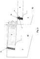
- FIG. 1a shows a perspective top view of a gas turbine blade with a Shroud 2, which has a rectangular shape on its radially oriented upper side Provides recess 10 into which the cover plate 6 radially completely from above is inserted.
- a solder seam 7 is between the cover plate 6 and the cover band 2 introduced, which completely surrounds the peripheral contour of the cover plate 6.
- Fig.1b is a cross section through any point transverse to the receiving contour shown within the shroud 2.
- the receiving contour of the shroud 2 has a first obliquely radially directed first step surface 11 and an axially oriented second step surface, the so-called bearing surface 12.
- the depth of the step the receiving contour is preferably chosen so that the surface of the Cover plate 6 is flush with the surface of the shroud 2.
- Intermediate gap 13 is provided, which is selected at least so large that a simple Insert the cover plate 6 in the receiving contour of the cover tape 2, due to a existing installation game 16 is possible.
- the between the cover plate 6 and The intermediate gap 13 located on the shroud 2 is subsequently covered with solder material 14 completely filled and soldered, the soldering material 14 being as small as possible Has ductility or high brittleness after the soldering process.
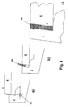
- Fig. 3a shows such a crack 15, which consists of two Zigzag-shaped, immediately opposite fracture surfaces composed. Because the course of the crack assumes a statistical course and therefore along the fracture surfaces has fracture surface sections that are oblique to Radial direction of the gas turbine blade and thus to that on the Gas turbine blade attacking centrifugal forces are inclined, carries an intimate Tooth between the cover plate 6 and the shroud along the soldered seam that the cover plate 6 cannot detach from the cover tape 2. Furthermore
- the loose, multi-point form-fit connection enables a seat that is free of bending stress the cover plate 6 within the cover band, whereby the cover plate 6 less mechanical tension and vibrations.
- FIG. 3b shows a joining variant using an additional one Closure strip 16, which is soldered on both sides by two solder seams 7, 7 '.
- the Closure strip 16 is made of a high temperature resistant material, which has a much higher ductility than the lathe material itself, so that the Sealing strip 16 for vibration damping of the cover plate 6 within of the shroud 2 contributes.
- Fig. 4a is the insertion process of the cover plate 6 in the receiving contour of the Shroud 2 shown.
- One between the cover tape 2 and the cover plate 6 existing installation play 16 ensures an unimpeded radial insertion of the Cover plate 6 in the cover band 2.
- Fig. 4b is the insertion of a closure piece 16 shown, which is inserted as a molded part in one piece in the intermediate gap 13.
- the closure piece 16 has a sufficiently high ductility as well High temperature resistance so that it is able to move between the Cover plate 6 and the cover band 2 forces occurring without damage.
- Fig. 4c is a force curve between the cover plate 6, the closure piece 17 and the shroud 2 shown.
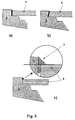
- FIG. 5a, b and c are different exemplary embodiments for Interlocking connections between cover plate 6 and cover band 2 shown.
- Fig. 5a is a radially directed gap between the cover tape 2 and Cover plate 6 filled with solder material.
- Fig. 5b shows an obliquely radially inclined solder gap.
- Fig. 5c the intermediate gap between cover plate 6 and Shroud 2 is formed radially and only in the upper area is one wedge-shaped solder connection 7 introduced. In this, it towers above Cover tape 2, the cover plate 6 a little, so that a triangular soldering wedge 7 can form between cover tape 2 and cover plate 6.
- a wedge-shaped solder connection 7 Crack course that is about 45 ° with respect to the radial direction and thus to a stable positive connection between the cover plate 6 and the Cover tape 2 leads.
- Fig. 6 shows a corresponding connection cross section between cover plate 6 and Cover band 2.
- a snap ring 18 introduced on both sides partially in the peripheral edge of the cover plate 6 and in the shroud 2 protrudes.
- a snap ring 18 can be provided rod-shaped moldings, which by lateral mounting openings within the cover tape and the cover plate can be brought in.
Landscapes
- Engineering & Computer Science (AREA)
- Mechanical Engineering (AREA)
- General Engineering & Computer Science (AREA)
- Turbine Rotor Nozzle Sealing (AREA)
Abstract
Description
- Fig. 1a
- perspektivische Draufsicht auf ein Deckband mit eingesetzter Deckplatte,
- Fig. 1 b
- Querschnitt durch die Aufnahmekontur eines Deckbandes mit eingefügter Deckplatte,
- Fig. 2a,b,c
- Darstellungen einer bekannte Deckplatte-DeckbandVerbindung (Stand der Technik),
- Fig. 3a, b
- Darstellungen zur Rissbildung innerhalb der Lötnaht,
- Fig. 4a bis c
- Formschlussverbindung mittels Einsatzteil,
- Fig. 5 a,b,c
- Darstellung alternativer Fügegeometrien,
- Fig. 6
- Darstellung von Formschlussverbindungen mittels mechanischem Haltemittel.
- 1
- Schaufelblatt
- 2
- Deckband
- 3
- Nutkontur
- 4,5
- Seitenkanten des Deckbandes
- 6
- Deckplatte
- 7
- Lötmaterial
- 8,9
- Seitenkanten des Deckbandes
- 10
- Ausnehmung
- 11
- Erste Stufenfläche
- 12
- Zweite Stufenfläche
- 13
- Zwischenspalt
- 14
- Lömaterial
- 15
- Riss
- 16
- Einbauspiel
- 17
- Verschlusselement
- 18
- Mechanisches Haltemittel
- K
- Kühlkanäle
Claims (12)
- Gekühlte Gasturbinenschaufel mit einem Deckband (2), in dem ein Kühlkanalsystem (K) vorgesehen ist, das radial zur Gasturbinenschaufel mit einer Deckplatte (6) abgeschlossen ist,
dadurch gekennzeichnet, dass die Deckplatte (6) einen Umfangsrand aufweist, längs dessen gesamter Erstreckung die Deckplatte (6) mit dem Deckband (2) eine durchgehende Formverbindung oder eine Vielzahl lokal begrenzter Formverbindungen eingeht. - Gekühlte Gasturbinenschaufel nach Anspruch 1,
dadurch gekennzeichnet, dass die Vielzahl lokal begrenzter Formverbindungen gleichmäßig längs des Umfangsrandes verteilt sind. - Gekühlte Gasturbinenschaufel nach Anspruch 1 oder 2,
dadurch gekennzeichnet, dass das Deckband (6) eine nach Form und Größe des Umfangsrandes der Deckplatte (2) angepaßte Aufnahmekontur aufweist, mit einem stufenförmigen Querschnitt, der eine radial- oder schräg radialwärts erste (11) und eine axialwärts orientierte zweite Stufenfläche (12), die sogenannte Auflagefläche, vorsieht und in die die Deckplatte (6) radialwärts auf die Auflagefläche aufsetzbar ist, und
dass im Bereich zwischen der ersten Stufenfläche (11) und dem Umfangsrand der Deckplatte (6) ein Haltemittel eingebracht ist, das die Formverbindung gewährleistet. - Gekühlte Gasturbinenschaufel nach Anspruch 3,
dadurch gekennzeichnet, dass zwischen der ersten Stufenfläche (11) und der in die Aufnahmekontur eingesetzten Deckplatte (6) ein Zwischenspalt (13) vorgesehen ist. - Gekühlte Gasturbinenschaufel nach Anspruch 4,
dadurch gekennzeichnet, dass die erste Stufenfläche (11) und der Umfangsrand geradlinig ausgebildet sind und der Zwischenspalt (13) eine weitgehend konstante Spaltbreite aufweist, und
dass der Zwischenspalt (13) radial oder schräg-radial zur Gasturbinenschaufellängsrichtung orientiert ist. - Gekühlte Gasturbinenschaufel nach einem der Ansprüche 3 bis 5,
dadurch gekennzeichnet, dass das Haltemittel ein Fügemittel ist, das im Bereich zwischen der ersten Stufenfläche (11) und dem Umfangsrand der Deckplatte (6) eingebracht ist und eine innige Fügeverbindung jeweils mit der ersten Stufenfläche (11) und dem Umfangsrand eingeht, und
dass innerhalb des Fügemittels längs der Erstreckung beider Fügeverbindungen wenigstens eine das Fügemittel vollständig durchsetzende Bruchfläche (15) vorgesehen ist mit schräg zur Radialrichtung verlaufenden Bruchflächenabschnitten. - Gekühlte Gasturbinenschaufel nach Anspruch 6,
dadurch gekennzeichnet, dass Fügemittel ein Lötmaterial (7) ist, das über keine oder nur geringe Duktiliät verfügt. - Gekühlte Gasturbinenschaufel nach einem der Ansprüche 3 bis 6,
dadurch gekennzeichnet, dass die erste Stufenfläche (11) derart bemessen ist, dass sie die in die Aufnahmekontur eingesetzte Deckplatte (6) überragt,
dass das Fügemittel zumindest oberhalb der Deckplatte (6) zwischen der Deckplatte (6) und der die Deckplatte (6) überragenden ersten Stufenfläche (11) vorgesehen ist, und dass die Bruchfläche (15) schräg radial das Fügemittel durchsetzt. - Gekühlte Gasturbinenschaufel nach Anspruch 8,
dadurch gekennzeichnet, dass die Bruchfläche (15) im Winkelbereich von etwa 45° bezogen auf die Deckplatte (6) verläuft. - Gekühlte Gasturbinenschaufel nach Anspruch 3,
dadurch gekennzeichnet, dass der Umfangsrand der Deckplatte (6) eine längs des Umfangsrandes verlaufende Befestigungskontur aufweist, in die ein mechanisches Haltemittel (18) einbringbar ist, und
dass längs der ersten Stufenfläche (11) eine zur Befestigungskontur der Deckplatte (6) korrespondierende Befestigungskontur vorgesehen ist, in die im verfügten Zustand der Deckplatte (6) innerhalb der Aufnahmekontur das mechanische Haltemittel (18) kraftschlüssig einmündet. - Gekühlte Gasturbinenschaufel nach Anspruch 10,
dadurch gekennzeichnet, dass das mechanische Haltemittel (18) eine Art Sprengring ist, der innerhalb der Befestigungskontur der Deckplatte (6) vorgesehen ist. - Gekühlte Gasturbinenschaufel nach Anspruch 10,
dadurch gekennzeichnet, dass das mechanische Haltemittel (18) aus einer Anzahl stangenförmig ausgebildeter Formkörper besteht, die durch seitliche Montageöffnungen innerhalb des Deckbandes zwischen Umfangsrand der Deckplatte und erster Stufenfläche in die Befestigungskontur einbringbar sind.
Applications Claiming Priority (2)
| Application Number | Priority Date | Filing Date | Title |
|---|---|---|---|
| DE10062907 | 2000-12-16 | ||
| DE10062907 | 2000-12-16 |
Publications (3)
| Publication Number | Publication Date |
|---|---|
| EP1215363A2 true EP1215363A2 (de) | 2002-06-19 |
| EP1215363A3 EP1215363A3 (de) | 2004-01-02 |
| EP1215363B1 EP1215363B1 (de) | 2005-10-05 |
Family
ID=7667527
Family Applications (2)
| Application Number | Title | Priority Date | Filing Date |
|---|---|---|---|
| EP01128572A Expired - Lifetime EP1215364B1 (de) | 2000-12-16 | 2001-11-30 | Vorrichtung zur Kühlung eines Deckbandes einer Gasturbinenschaufel |
| EP01128573A Expired - Lifetime EP1215363B1 (de) | 2000-12-16 | 2001-11-30 | Gekühlte Gasturbinenschaufel |
Family Applications Before (1)
| Application Number | Title | Priority Date | Filing Date |
|---|---|---|---|
| EP01128572A Expired - Lifetime EP1215364B1 (de) | 2000-12-16 | 2001-11-30 | Vorrichtung zur Kühlung eines Deckbandes einer Gasturbinenschaufel |
Country Status (4)
| Country | Link |
|---|---|
| US (2) | US6589011B2 (de) |
| EP (2) | EP1215364B1 (de) |
| JP (1) | JP2002201907A (de) |
| DE (4) | DE10131073A1 (de) |
Cited By (1)
| Publication number | Priority date | Publication date | Assignee | Title |
|---|---|---|---|---|
| US7427188B2 (en) | 2004-09-16 | 2008-09-23 | Alstom Technology Ltd | Turbomachine blade with fluidically cooled shroud |
Families Citing this family (10)
| Publication number | Priority date | Publication date | Assignee | Title |
|---|---|---|---|---|
| EP1503330B1 (de) | 2002-05-09 | 2010-06-02 | Sony Corporation | Verfahren zum erkennen eines biologischen musters, detektor für biologische muster, verfahren für biologische zertifikate und biologische zertifikatvorrichtung |
| US20070048122A1 (en) * | 2005-08-30 | 2007-03-01 | United Technologies Corporation | Debris-filtering technique for gas turbine engine component air cooling system |
| US20110110772A1 (en) * | 2009-11-11 | 2011-05-12 | Arrell Douglas J | Turbine Engine Components with Near Surface Cooling Channels and Methods of Making the Same |
| US9133724B2 (en) * | 2012-01-09 | 2015-09-15 | General Electric Company | Turbomachine component including a cover plate |
| US9567857B2 (en) | 2013-03-08 | 2017-02-14 | Rolls-Royce North American Technologies, Inc. | Turbine split ring retention and anti-rotation method |
| US10590785B2 (en) * | 2014-09-09 | 2020-03-17 | United Technologies Corporation | Beveled coverplate |
| DE102017208680A1 (de) | 2017-05-23 | 2018-11-29 | Siemens Aktiengesellschaft | Verfahren zum Befestigen eines Kühlbleches an einer Turbinenschaufel |
| US10370300B2 (en) * | 2017-10-31 | 2019-08-06 | General Electric Company | Additively manufactured turbine shroud segment |
| US11156102B2 (en) * | 2018-03-19 | 2021-10-26 | General Electric Company | Blade having a tip cooling cavity and method of making same |
| CN114405715B (zh) * | 2021-12-28 | 2023-08-18 | 东方电气集团东方汽轮机有限公司 | 一种燃气轮机空心叶片喷涂用装夹工装 |
Family Cites Families (18)
| Publication number | Priority date | Publication date | Assignee | Title |
|---|---|---|---|---|
| NL88170C (de) * | 1952-10-31 | 1900-01-01 | ||
| US3756020A (en) * | 1972-06-26 | 1973-09-04 | Curtiss Wright Corp | Gas turbine engine and cooling system therefor |
| US3781129A (en) * | 1972-09-15 | 1973-12-25 | Gen Motors Corp | Cooled airfoil |
| GB1530256A (en) * | 1975-04-01 | 1978-10-25 | Rolls Royce | Cooled blade for a gas turbine engine |
| US4017209A (en) * | 1975-12-15 | 1977-04-12 | United Technologies Corporation | Turbine rotor construction |
| US4086757A (en) * | 1976-10-06 | 1978-05-02 | Caterpillar Tractor Co. | Gas turbine cooling system |
| US4712979A (en) * | 1985-11-13 | 1987-12-15 | The United States Of America As Represented By The Secretary Of The Air Force | Self-retained platform cooling plate for turbine vane |
| US4752184A (en) * | 1986-05-12 | 1988-06-21 | The United States Of America As Represented By The Secretary Of The Air Force | Self-locking outer air seal with full backside cooling |
| US5350277A (en) * | 1992-11-20 | 1994-09-27 | General Electric Company | Closed-circuit steam-cooled bucket with integrally cooled shroud for gas turbines and methods of steam-cooling the buckets and shrouds |
| JP3188105B2 (ja) | 1994-07-11 | 2001-07-16 | 三菱重工業株式会社 | ガスタービンの動翼 |
| US5634766A (en) * | 1994-08-23 | 1997-06-03 | General Electric Co. | Turbine stator vane segments having combined air and steam cooling circuits |
| DE19643716A1 (de) * | 1996-10-23 | 1998-04-30 | Asea Brown Boveri | Schaufelträger für einen Verdichter |
| JP3316415B2 (ja) * | 1997-05-01 | 2002-08-19 | 三菱重工業株式会社 | ガスタービン冷却静翼 |
| JP2955252B2 (ja) * | 1997-06-26 | 1999-10-04 | 三菱重工業株式会社 | ガスタービン動翼チップシュラウド |
| GB9815611D0 (en) * | 1998-07-18 | 1998-09-16 | Rolls Royce Plc | Improvements in or relating to turbine cooling |
| US6179555B1 (en) * | 1998-10-06 | 2001-01-30 | Pratt & Whitney Canada Corp. | Sealing of T.O.B.I feed plenum |
| GB2365930B (en) * | 2000-08-12 | 2004-12-08 | Rolls Royce Plc | A turbine blade support assembly and a turbine assembly |
| US6454526B1 (en) * | 2000-09-28 | 2002-09-24 | Siemens Westinghouse Power Corporation | Cooled turbine vane with endcaps |
-
2001
- 2001-06-27 DE DE10131073A patent/DE10131073A1/de not_active Withdrawn
- 2001-06-28 DE DE10131370A patent/DE10131370A1/de not_active Withdrawn
- 2001-11-30 EP EP01128572A patent/EP1215364B1/de not_active Expired - Lifetime
- 2001-11-30 EP EP01128573A patent/EP1215363B1/de not_active Expired - Lifetime
- 2001-11-30 US US09/996,693 patent/US6589011B2/en not_active Expired - Lifetime
- 2001-11-30 DE DE50107607T patent/DE50107607D1/de not_active Expired - Lifetime
- 2001-11-30 DE DE50106966T patent/DE50106966D1/de not_active Expired - Lifetime
- 2001-11-30 US US09/996,684 patent/US6682304B2/en not_active Expired - Fee Related
- 2001-12-17 JP JP2001383503A patent/JP2002201907A/ja active Pending
Cited By (1)
| Publication number | Priority date | Publication date | Assignee | Title |
|---|---|---|---|---|
| US7427188B2 (en) | 2004-09-16 | 2008-09-23 | Alstom Technology Ltd | Turbomachine blade with fluidically cooled shroud |
Also Published As
| Publication number | Publication date |
|---|---|
| US6682304B2 (en) | 2004-01-27 |
| US20020127103A1 (en) | 2002-09-12 |
| EP1215364A3 (de) | 2004-01-02 |
| DE50107607D1 (de) | 2006-02-16 |
| EP1215363B1 (de) | 2005-10-05 |
| EP1215363A3 (de) | 2004-01-02 |
| JP2002201907A (ja) | 2002-07-19 |
| US20020136635A1 (en) | 2002-09-26 |
| US6589011B2 (en) | 2003-07-08 |
| DE10131073A1 (de) | 2002-06-20 |
| EP1215364B1 (de) | 2005-08-03 |
| DE10131370A1 (de) | 2002-06-20 |
| DE50106966D1 (de) | 2005-09-08 |
| EP1215364A2 (de) | 2002-06-19 |
Similar Documents
| Publication | Publication Date | Title |
|---|---|---|
| DE69005845T2 (de) | Diaphragmaaufbau eines Verdichters. | |
| DE69105837T2 (de) | Gekühlte Turbinenschaufel. | |
| DE69502282T2 (de) | Turbinengehäusesegment mit haarnadelförmigen kühlkanälen | |
| DE69933601T2 (de) | Gasturbine | |
| DE2717810C2 (de) | Gasturbinenläufer mit keramischen Schaufeln | |
| EP3056813B1 (de) | Abdichtung eines randspalts zwischen effusionsschindeln einer gasturbinenbrennkammer | |
| DE2737622C2 (de) | Turbinenmantel | |
| DE2718661C2 (de) | Leitschaufelgitter für eine axial durchströmte Gasturbine | |
| DE102004024683B4 (de) | Dichtungssystem für horizontale Verbindungsstellen von Zwischenböden von Dampfturbinen | |
| DE3211139C1 (de) | Axialturbinenschaufel,insbesondere Axialturbinenlaufschaufel fuer Gasturbinentriebwerke | |
| DE602005000350T2 (de) | Turbinenstatorschaufel mit verbesserter Kühlung | |
| EP1505254B1 (de) | Gasturbine und zugehöriges Kühlverfahren | |
| DE19809008A1 (de) | Gasturbinenschaufel | |
| DE102010016620A1 (de) | Turbinenleitapparat mit Seitenwandkühlplenum | |
| DE4027812A1 (de) | Selbstkuehlende stossverbindung | |
| EP0806546A1 (de) | Thermisch belastete Strömungsmaschinenschaufel mit keramischen Vorderkanteneinsatz | |
| DE60035247T2 (de) | Gasturbinenschaufel | |
| EP1201879A2 (de) | Gekühltes Bauteil, Gusskern für die Herstellung eines solchen Bauteils, sowie Verfahren zum Herstellen eines solchen Bauteils | |
| DE1601557A1 (de) | Stroemungsmittelgekuehlte Statoranordnung | |
| EP1215363A2 (de) | Gekühlte Gasturbinenschaufel | |
| DE19914227B4 (de) | Wärmeschutzvorrichtung in Gasturbinen | |
| DE69812837T2 (de) | Doppelkreuzdichtung für Gasturbinenleitschaufeln | |
| EP3658751B1 (de) | Schaufelblatt für eine turbinenschaufel | |
| EP1163430A1 (de) | Abdeckelement und anordnung mit einem abdeckelement und mit einer tragstruktur | |
| EP1207268A1 (de) | Filmkühlung von Gasturbinenschaufeln mittels Schlitzen für Kühlluft |
Legal Events
| Date | Code | Title | Description |
|---|---|---|---|
| PUAI | Public reference made under article 153(3) epc to a published international application that has entered the european phase |
Free format text: ORIGINAL CODE: 0009012 |
|
| AK | Designated contracting states |
Kind code of ref document: A2 Designated state(s): AT BE CH CY DE DK ES FI FR GB GR IE IT LI LU MC NL PT SE TR |
|
| AX | Request for extension of the european patent |
Free format text: AL;LT;LV;MK;RO;SI |
|
| RAP1 | Party data changed (applicant data changed or rights of an application transferred) |
Owner name: ALSTOM (SWITZERLAND) LTD |
|
| PUAL | Search report despatched |
Free format text: ORIGINAL CODE: 0009013 |
|
| AK | Designated contracting states |
Kind code of ref document: A3 Designated state(s): AT BE CH CY DE DK ES FI FR GB GR IE IT LI LU MC NL PT SE TR |
|
| AX | Request for extension of the european patent |
Extension state: AL LT LV MK RO SI |
|
| RIC1 | Information provided on ipc code assigned before grant |
Ipc: 7F 01D 9/04 B Ipc: 7F 01D 5/18 A |
|
| RAP1 | Party data changed (applicant data changed or rights of an application transferred) |
Owner name: ALSTOM TECHNOLOGY LTD |
|
| 17P | Request for examination filed |
Effective date: 20040630 |
|
| AKX | Designation fees paid |
Designated state(s): DE GB |
|
| 17Q | First examination report despatched |
Effective date: 20040927 |
|
| GRAP | Despatch of communication of intention to grant a patent |
Free format text: ORIGINAL CODE: EPIDOSNIGR1 |
|
| GRAS | Grant fee paid |
Free format text: ORIGINAL CODE: EPIDOSNIGR3 |
|
| GRAA | (expected) grant |
Free format text: ORIGINAL CODE: 0009210 |
|
| AK | Designated contracting states |
Kind code of ref document: B1 Designated state(s): DE GB |
|
| REG | Reference to a national code |
Ref country code: GB Ref legal event code: FG4D Free format text: NOT ENGLISH |
|
| GBT | Gb: translation of ep patent filed (gb section 77(6)(a)/1977) |
Effective date: 20051212 |
|
| REF | Corresponds to: |
Ref document number: 50107607 Country of ref document: DE Date of ref document: 20060216 Kind code of ref document: P |
|
| PLBE | No opposition filed within time limit |
Free format text: ORIGINAL CODE: 0009261 |
|
| STAA | Information on the status of an ep patent application or granted ep patent |
Free format text: STATUS: NO OPPOSITION FILED WITHIN TIME LIMIT |
|
| 26N | No opposition filed |
Effective date: 20060706 |
|
| PGFP | Annual fee paid to national office [announced via postgrant information from national office to epo] |
Ref country code: GB Payment date: 20101022 Year of fee payment: 10 |
|
| PGFP | Annual fee paid to national office [announced via postgrant information from national office to epo] |
Ref country code: DE Payment date: 20111130 Year of fee payment: 11 |
|
| GBPC | Gb: european patent ceased through non-payment of renewal fee |
Effective date: 20121130 |
|
| REG | Reference to a national code |
Ref country code: DE Ref legal event code: R119 Ref document number: 50107607 Country of ref document: DE Effective date: 20130601 |
|
| PG25 | Lapsed in a contracting state [announced via postgrant information from national office to epo] |
Ref country code: DE Free format text: LAPSE BECAUSE OF NON-PAYMENT OF DUE FEES Effective date: 20130601 |
|
| PG25 | Lapsed in a contracting state [announced via postgrant information from national office to epo] |
Ref country code: GB Free format text: LAPSE BECAUSE OF NON-PAYMENT OF DUE FEES Effective date: 20121130 |